JavaScript is disabled. For a better experience, please enable JavaScript in your browser before proceeding.
1 - 18 of 18 Posts
1 - 18 of 18 Posts
Top
ChinaRiders Forums > Technical/Performance > ATVs > No spark on 110cc mini atv
PDA
View Full Version : No spark on 110cc mini atv
l00ker
11-19-2009, 08:35 PM
I have no spark and can NOT figure it out. I have checked and replaced everything. I have replaced the CDI and the ignition coil and spark plug. I checked and made sure I was getting voltage out of the stator, but still no spark. It just keeps turning over. I keep thinking it is a safety switch of a bad ground, but I have traced EVERYTHING and can not see any problems. Checked all connections and they also look good.
PLEASE HELP with any ideas .... I have to be missing something.
waynec
11-19-2009, 08:43 PM
The kill switches on these are hatefull little prickish things. Its not enough to have it centered. It needs to be pushed in as well. Even then it is hard to detect any change..but it does make contact.....waynec
l00ker
11-19-2009, 08:54 PM
Which ones in particular should I be paying attention too? Is there any one that is worse than the other?
TurboT
11-19-2009, 09:27 PM
Which ones in particular should I be paying attention too? Is there any one that is worse than the other?
Not sure which brand you have here, but I guess it doesn't make much difference.
Please pay very careful attention to the wiring harnesses and white connector plugs. It is very easy for spade type connectors to slide out of them some and not make contact.
I would also trace your wiring to make sure it's in the correct place. I've seen some of them come with the wires in the wrong spot inside the connector. It's a bastard of a job to find this problem, but a very simple fix.
I would highly doubt any of the parts you replaced would be the issue, and would bet you $10 it's a stupid wire in the wrong spot, or pulled out some.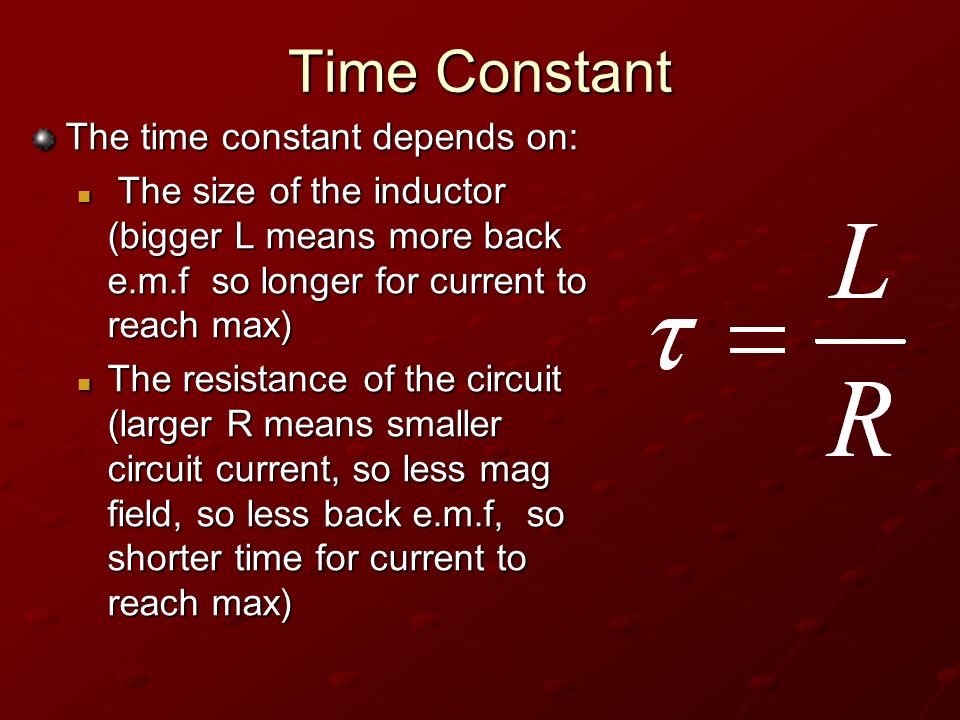
As waynec mentioned, the rubber plug dead man switch located on the back of them can be a problem as well. You need to ensure the boot is on correctly if it's slightly ajar you won't get spark.
I am assuming you're squeezing the brake if it's turning over.
l00ker
11-19-2009, 09:32 PM
Correct brake is set. I have traced EVERYTHING and cannot get spark. I even replaced the tether kill switch in the back with a brand new one. Still no spark. I am lost .... Any other suggestions on what to look for would be great!
MICRider
11-19-2009, 09:46 PM
Does kind of sound like the safety switch... With your brake set, does your brake light come on?
l00ker
11-19-2009, 09:57 PM
Brake light does come on. Correct me if I am wrong but the only saftey switches that will cause no spark is the rear tether and the key ignition switch and the handlebar kill switch.
The brake lever has nothing to do with spark.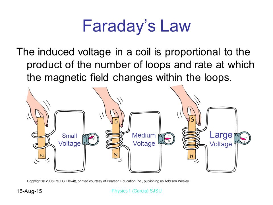 It is only to be pulled in order to get it to turn over.
What else would cause no spark ... I have been trying to track this down for 2 days. Again ... I have traced and untaped and uncovered every wire and checked every connection. I can not figure this out. Again, I have also replaced the CDI, iginition coil, tether safety switch, ignition switch, and spark plug. Still NO SPARK .....
MICRider
11-19-2009, 10:08 PM
Brake light does come on. Correct me if I am wrong but the only saftey switches that will cause no spark is the rear tether and the key ignition switch and the handlebar kill switch.
The brake lever has nothing to do with spark. It is only to be pulled in order to get it to turn over.
What else would cause no spark ... I have been trying to track this down for 2 days. Again ... I have traced and untaped and uncovered every wire and checked every connection. I can not figure this out. Again, I have also replaced the CDI, iginition coil, tether safety switch, ignition switch, and spark plug. Still NO SPARK .....
This will sound stupid and is not meant to annoy you, but is the spark plug boot making good contact on the spark plug wire? On my sons Mini Beast, the wire pulled out of the connector that goes onto the plug. I remember on my old japanese bikes some of them kind of threaded on but on the Gio it just seemed to push on.
Again, I am sure you checked that already but just wanted to throw it out there. There is an electrical guru that frequents the forums named LynnEdwards (spelling could be wrong) that could probably help but I haven't seen him on for a while.
Sounds like you have covered pretty well all the bases on it. Electrical problems can be major gremlins to track... Very frustrating. I wish you the best of luck with it and am sure you will track it down.
TurboT
11-19-2009, 10:24 PM
What brand is it?
Has it ever run or is this a new quad for you?
Have you ground the plug on a headbolt to see if there is actually no spark?
Have you replaced the spark plug with a new one? If so, what brand?
What kind of kill switch is it on the handlebar? Is it a two position switch(click on and off) or is it a slider style like on a motorcycle turn signal switch?
Sorry for the rapid fire questions, but it helps narrow down the solution gathering.
l00ker
11-20-2009, 12:31 AM
- It is a used quad not new
- it is the on/off toggle switch on the handle bar
- Yes, plug is making good contact on the boot. As mentioned earlier it is a new coil with a new wire going to the plug
- Yes, I have tried grounding to the head to see if I can see spark ... even held it in my hand while touching a ground to see if I could even feel the slightest tingle and nothing.
- Tested with a meter and I am getting current from the stator to the CDI, but I am getting nothing coming out of the CDI to the ignition coil. It has to be shorting or grounding prior to the CDI I just can not find it....
- It can only be a couple of wires, but I have checked the logical ones ... tether kill switch, handlebar switch, and ignition switch.
LynnEdwards
11-20-2009, 01:17 AM
Is this a picture of your CDI?
http://i397.photobucket.com/albums/pp60/LynnEdwards_photo/50cc-cdi. jpg
jpg
If so, set up your quad to run - all kill switches off, tether plug in place, ignition switch on. Then unplug the CDI and use you meter to measure the kill switch pin resistance (in ohms) in the wiring harness to ground. It should read infinite ohms (open circuit). If it reads a very low value of resistance (less than 100 ohms) then you have a kill switch problem. We can go from there.
If you have a different CDI such as a 4 pin version (much less common than the above 5 pin version) then that's a complete different path.
If you don't have a kill switch problem then the next step is to use your meter to measure the power supply voltage to the CDI, the trigger voltage to the CDI, and the resistance of the coil primary to ground. We can go there if necessary.
Kill switch issues (and associated wiring) are the most common causes of no spark and the easiest to fix. That's the place to start. We can branch out from there as needed.
l00ker
11-20-2009, 08:37 PM
OK here is the update.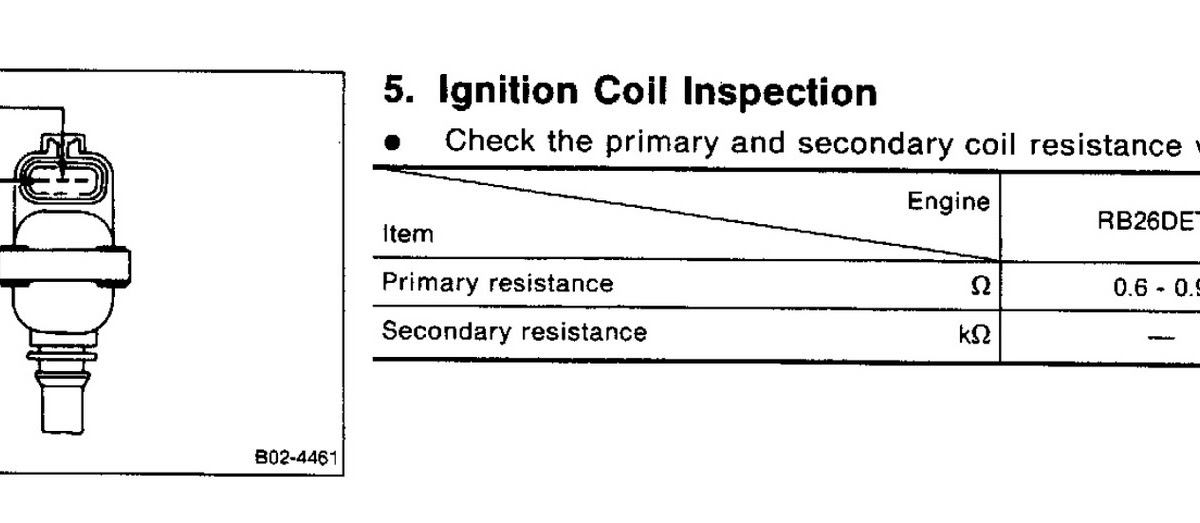 My CDI does look like the picture. I tested the kill switch pin and it reads infinite ohms as it should. It is not a kill switch problem. The power supply to the CDI from the stator is only reading between 60 - 65 volts AC. I am getting absolutely zero volts coming out of the CDI to the coil. The timing trigger pin measures .2 volts.
Is the stator not producing enough volts to trigger the CDI?
LynnEdwards
11-21-2009, 01:38 AM
60 volts AC on the ignition power pin is fine.
0.2 volts AC on the trigger wire is on the low side. It really depends on your meter. Since you didn't report something like 0.23 volts AC I'm assuming that your least significant digit on the meter is 0.1 volts on the AC ranges. So it really could be more like 0.1 volts (or 0.3 volts).
The trigger voltage is actually very complicated. It really consists of two closely spaced +/- pulses about 5 volts high (at cranking speeds) followed by long periods of zero volts in between.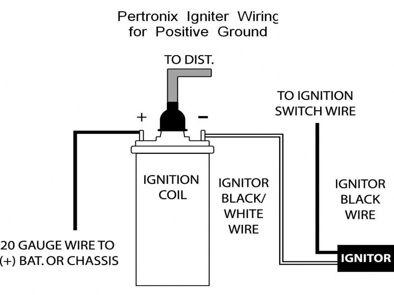 Volt meters aren't really designed to measure this kind of complex waveform, so there is some variation between meters. Using a meter to measure this is not optimum, but often the only option.
As another data point try measuring the resistance of this pin in the wiring harness to ground (CDI unplugged). You should get around 150 ohms.
Just for informational purposes this is a graphic display of what the voltage should be on that pin:
http://i397.photobucket.com/albums/pp60/LynnEdwards_photo/1jpg.jpg
The relatively long periods of zero volts between pulse pairs is why you read much less than the 5 volt peaks.
The trigger pickup coil is outside the flywheel, but under the engine cover. On some quads the gap between the pickup coil and the flywheel is adjustable. You might want to see if yours is adjustable, and then try narrowing the gap. That will increase your trigger voltage substantially. I have read posts from others who have solved their no spark problem by narrowing this gap.
Also make sure that the connection from the CDI output through the ignition coil primary is OK. Measure the resistance from the Ignition Coil pin in the wiring harness to ground. You should get around 1-2 ohms. You should not get zero ohms.
l00ker
11-21-2009, 12:06 PM
Thanks for the help ... I will try this afternoon and let you know!
HotelRed
11-22-2009, 10:43 PM
Back to the kill switch. I had a similar problem recently. I wound up taking the handlebar kill switch apart & found a bunch of crud in there. Cleaned it up & she fires up just fine now.
Good luck.
John
l00ker
11-23-2009, 01:19 PM
Kill switch is fine. Took it apart and found no problems.
I am measuring .1 volts AC on the timing trigger
I am now measuring 55 volts AC on the ignition power pin (I am assuming it is dropping due to battery going low)
I am measuring 120 ohms resistance on the trigger pin to ground
I am measuring 1 ohms on the ignition coil primary pin to ground.
Still no spark and have no idea where to go next ......
I have already tried 2 CDIs (new) .... could both be bad??
waynev
11-23-2009, 01:28 PM
OK, only 1 more thing i can think of, does the quad have one of those remote start/stops on it?, maybe the alarm is armed and not allowing any spark.
l00ker
11-23-2009, 01:41 PM
No alarm / remote kill.
waynev
11-23-2009, 02:30 PM
Do you know what kind of quad you have other than "USED".
l00ker
11-23-2009, 03:39 PM
I do not know the specific model. It is identical to the Roketa, Tao-Tao, or the Gio mini 110cc. They are all the same.
TurboT
11-23-2009, 05:56 PM
Frustrating stuff.. I hate being a parts changer, but what about the ignition wire/spark plug wire itself..
You mention you changed the coil, but did you put a new spark plug wire on as well?
It sounds as if you have power/signal everywhere but to the plug, and it is the delivery method, and a cheap part to throw on.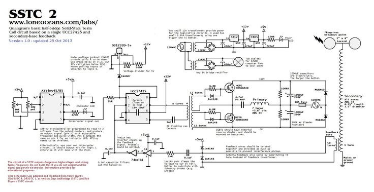
I'll also let Lynn Edwards review your data too for more thoughts.
There is also a little part, jammed up under the body kit, I believe on the left hand side (If sitting on the quad). It's called the rectifier and has a four pin plug in it. Have you checked the wiring here? I had a 110cc Mini Hummer not sparking and this was the culprit, one of the wires was slightly pulled back out of the white connector, almost didn't notice it but it was just not quite making contact inside. The way it was wired and set, there was some pressure moving away from the plug, causing the wires to want to pull back. I had to shove them all in again and tape the wires to the frame to keep them from moving back. It's run ever since.
waynev
11-23-2009, 06:49 PM
That sounds like it might be something worth looking at T, here's a pic of the wiring diagram from my gio 50cc and as T mentioned there is a wire going from the recifier to the CDI box.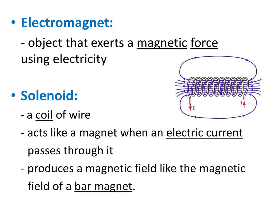
http://i646.photobucket.com/albums/uu188/waynebrandy/GIO10012.jpg
l00ker
11-23-2009, 10:04 PM
Thanks for the input. The rectifier is the ONLY thing that I have not looked at. Yes, When I put the new coil on it came with all new wires including the plug wire. I will look at the rectifier tomorrow.
Thanks for all of the input!
TurboT
11-23-2009, 10:27 PM
Keep us posted!
LynnEdwards
11-24-2009, 02:48 AM
Kill switch is fine. Took it apart and found no problems.
I am measuring .1 volts AC on the timing trigger
I am now measuring 55 volts AC on the ignition power pin (I am assuming it is dropping due to battery going low)
I am measuring 120 ohms resistance on the trigger pin to ground
I am measuring 1 ohms on the ignition coil primary pin to ground.
Still no spark and have no idea where to go next ......
I have already tried 2 CDIs (new) . ... could both be bad??
The AC Ignition power output voltage is directly proportional to engine speed, so a lower charged battery (and associated lower cranking speeds) will cause lower output voltage. 55 AC volts is still good enough to power the CDI.
The only thing that looks abnormal to me is the 0.1 volt trigger voltage. It's low, but is it just your meter or a real problem? I don't know the answer to this. I use an oscilloscope to measure this voltage, but most don't have access to one of these
If you're ambitious you could make this:
http://i397.photobucket.com/albums/pp60/LynnEdwards_photo/9jpg.jpg
One lead goes to the trigger pin, the other to ground (polarity doesn't matter).
The two back to back LED's will both flash when hooked to a working quad trigger pin. One LED flashes on the negative pulse, the other flashes on the positive pulse. You really could use any LED. The green ones don't conduct until they get 2.5 volts or so across them. Red LED's are around 1.8 volts. What this circuit does is prove that the trigger pin produces enough voltage to fire the CDI. At cranking speeds both LED's should blink at 10 times per second.
Also, there 's been a lot of talk about kill switches. Normally measuring the kill switch pin resistance to ground is sufficient to rule out these types of problems, but I was thinking that maybe there might be a problem with corrosion across one or more of the kill switch connections. Corroded contacts can be very nonlinear - they might look open for low voltages, but look very conductive at high voltages. This possibility can be eliminated completely by removing the kill switch wire. Remove the pin or cut the wire to the harness (you can always solder it back). Then check for spark. This eliminates all kill switches - all of them - end of story. But be aware, if the quad starts you will have no way to turn it off. So be prepared to hook it back up to be able to stop the quad - and remember that it has high voltage on it so you just can't grab it with you fingers to reconnect it. Use insulated pliers or whatever.
Two more data points that might shed light:
1) Disconnect the CDI, and measure the kill switch voltage while cranking the engine. This waveform is complex and consists of AC and DC components. Measure both AC voltage and DC voltage on this pin and report both. What this measurement does is look inside the CDI internal supply voltage.
2) With the CDI disconnected, set your meter to measure AC current on a 200 mA scale (or so). While cranking the engine measure the output current to ground on the AC power pin. You are shorting the stator ignition power pin to ground when when doing this through your meter. The short circuit current is another verification that the stator can put out power as well as voltage. Power is voltage times current. Shorting out your stator will not hurt anything.
With the last two tests I'm just looking for more clues.
Cal25
11-24-2009, 09:35 AM
Lynn, I must say you are a much valued resource here. Thank you very much for your detailed help.
MICRider
11-24-2009, 08:22 PM
Lynn, I must say you are a much valued resource here. Thank you very much for your detailed help.
I second that, LynnEdwards knows a tremendous amount about electrical, I wish I was as knowledgable :)
Weldangrind
11-25-2009, 01:32 AM
I second that, LynnEdwards knows a tremendous amount about electrical, I wish I was as knowledgable :)
I think that we all have the opportunity to learn each time LynnEdwards posts. :D
TurboT
11-25-2009, 01:38 AM
I second that, LynnEdwards knows a tremendous amount about electrical, I wish I was as knowledgable :)
I think that we all have the opportunity to learn each time LynnEdwards posts. :D
Unless it goes right over your head like the last post ... 8O
All kidding aside it's wonderful stuff and one day when I haven't been sniffing too much glue I will re-read and try to take that all in.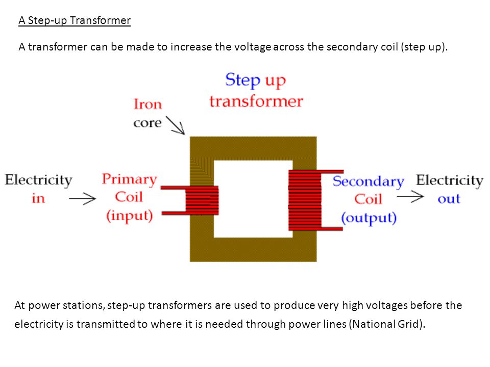 :)
:)
Thanks for your contributions, LynnEdwards.. hopefully it helps the authour of this thread find the gremlin, and others to follow!!
Turnburn99
11-25-2009, 11:04 AM
I second that, LynnEdwards knows a tremendous amount about electrical, I wish I was as knowledgable :)
I think that we all have the opportunity to learn each time LynnEdwards posts. :D
I agree, there has been a terrific amount of valuable information shared on this thread and many others. This is a great site with many knowledgeable helpful people! Thanks to all! I hope that the trouble with your quad will be sorted out soon. :)
MICRider
11-29-2009, 05:37 PM
Hmmm... Wonder if the original poster ever got his mini atv running?
TurboT
11-29-2009, 05:56 PM
Hopefully he comes back and shares. I'm interested to know if it's fixed or not..
l00ker
12-01-2009, 11:23 AM
Thanks for all your help . .. been busy with the holidays. ATV is still not running, but I am a little closer. I am now getting spark! Turns out it was a connection at the rectifier. Now I am not getting gas out of the carb. It starts and runs when starting fluid is sprayed in the carb with the air filter off. Then dies when the fluid burns off. Now time to take the carb apart! I'll keep you all posted.
Any quick suggestions on where to focus in on? I know I am getting gas out of the tank to the carb, but obviously not from the carb to the cylinder. I did drain the carb and put fresh gas in. This is the stock carb and due to lack of funds can not replace with a Mikuni (unfortunately).
I have done carbs before, but usually just for re-jetting and normal cleaning. What adjustments might need to be done? It might be just a stuck float ....
Thanks again for all the help!!!
HotelRed
12-01-2009, 12:12 PM
I had to take my carb apart for the same reason. There was crud in there and an ant blocking the low speed jet. Cleaned it & ran a thin wire through the jets & all is fine now.
Good luck.
John
Weldangrind
12-01-2009, 12:25 PM
When they misbehave, I usually dismantle the carb (including jets and float valves) and spray a can of carb cleaner through every passage. it's cheap at WalMart. I shy away from wire because brass jets are pretty soft.
If fuel wasn't pouring out of the overflow hose, the float isn't likely to be stuck.
Congrats on finding the rectifier problem. :D
TurboT
12-01-2009, 02:15 PM
Congrats on finding the rectifier problem. :D
X 2!
Dirty rotten rectifier's!
MICRider
12-01-2009, 08:39 PM
Cool! Spark is the hard one, I'm sure with a good carb cleaning you will have it purring. I don't know if anyone linked this yet but I will if nobody did :)
http://forums. atvconnection.com/chinese-quads/226524-how-carb-adjustment-any-chinese-atv-kazuma-yamoto-redcat-baja-sunl-etc.html
Oh, tons of good carb tips on here too, just have to do a search on the forums for it.
LynnEdwards
12-02-2009, 01:57 AM
... I am now getting spark! Turns out it was a connection at the rectifier....
I'm glad you're getting spark, and I certainly hope it stays that way. But I'm in a quandry... Do I let sleeping dogs lie, or warn you that there's a sleeping dog nearby that might wake back up...
I don't think problems with your rectifier has anything to do with your "no spark" problem. There are two independent power supply systems on your quad. One is the 12 volt system which includes your battery, the battery charge winding on your stator, the rectifier/regulator, the starter, lights, etc. The other is the ignition system power which is AC and moderately high voltage (one to several hundred volts). They aren't related (or connected) at all. You need the battery to spin the engine and get it started (unless you also have a kick start). Once the quad is started you can remove the battery and rectifier/regulator altogether and the quad will still run. With all this 12 volt stuff removed, and if you have a kick start, the quad will start up fine. All the ignition stuff is running off the stator high voltage ignition winding, and triggered by the the third stator winding outside the flywheel.
If someone told you that they had problems with their car idling rough, and then after a lot of trying different things they said he finally fixed it by tightening up the wheel lug nuts, what would you tell them?
Note (for completeness only): There are quad ignition systems that run off 12 volts, but not if you have a five pin CDI, plus you already verified that the CDI is powered with 65 volts AC while cranking. 12 volt powered ignitions are found on some newer quads, and are much less common. On these quads the high voltage winding from the stator is missing, or not wired up to the CDI.
As far as carburetors, I found this generic youtube video quite good:
http://www.youtube.com/watch?v=4azg3hIl9oI
waynev
12-02-2009, 01:36 PM
... I am now getting spark! Turns out it was a connection at the rectifier....
I'm glad you're getting spark, and I certainly hope it stays that way. But I'm in a quandry... Do I let sleeping dogs lie, or warn you that there's a sleeping dog nearby that might wake back up...
I don't think problems with your rectifier has anything to do with your "no spark" problem. There are two independent power supply systems on your quad. One is the 12 volt system which includes your battery, the battery charge winding on your stator, the rectifier/regulator, the starter, lights, etc. The other is the ignition system power which is AC and moderately high voltage (one to several hundred volts). They aren't related (or connected) at all. You need the battery to spin the engine and get it started (unless you also have a kick start). Once the quad is started you can remove the battery and rectifier/regulator altogether and the quad will still run. With all this 12 volt stuff removed, and if you have a kick start, the quad will start up fine. All the ignition stuff is running off the stator high voltage ignition winding, and triggered by the the third stator winding outside the flywheel.
If someone told you that they had problems with their car idling rough, and then after a lot of trying different things they said he finally fixed it by tightening up the wheel lug nuts, what would you tell them?
Note (for completeness only): There are quad ignition systems that run off 12 volts, but not if you have a five pin CDI, plus you already verified that the CDI is powered with 65 volts AC while cranking. 12 volt powered ignitions are found on some newer quads, and are much less common. On these quads the high voltage winding from the stator is missing, or not wired up to the CDI.
As far as carburetors, I found this generic youtube video quite good:
http://www.youtube.com/watch?v=4azg3hIl9oI
I agree with your thinking lynn, but looking at the wiring diagram i posted, the wire coming from the recifier to the CDI looks like it is the grounding wire, and a CDI with out a ground would be a major cause of no spark, agree ?
TurboT
12-02-2009, 05:22 PM
I would never argue with LynnEdwards' logic. However this would be the second example I know of, with wires pulled out of the rectifier harness causing no spark. I *know* it fixed the one I was involved in, because as soon as I pushed the wires back in it fired right up, and the vibration and location of the wires kept loosening it and falling out again, no spark. Once I got it to stay it's run ever since.
It's a bit odd given the supplied theory. .
.
LynnEdwards
12-03-2009, 01:13 AM
I agree with your thinking lynn, but looking at the wiring diagram i posted, the wire coming from the recifier to the CDI looks like it is the grounding wire, and a CDI with out a ground would be a major cause of no spark, agree ?
You raise a very good point. A CDI will not work without a ground. When I look back through my previous posts I never once suggested measuring the ground wire of the CDI to see it had continuity to frame ground. A major oversight on my part. Good call!
The ignition system doen't need a ground wire specifically going to the rectifier to work. It just needs a connection to frame ground somewhere in the wiring harness. It is possible that connection routes through the rectifier ground connection. You may have nailed it!
l00ker
12-03-2009, 04:01 PM
I am going out now to pull the carb apart to give it a good cleaning. I will double check and tell everyone the specific wire that was causing the no spark. I will post my findings tonight.
Again BIG THANKS to everyone for their help!
l00ker
12-03-2009, 11:56 PM
ATV is now running! A good carb cleaning did the trick. Still needs a little adjstment, but runs OK.
I double checked the spark and I am unclear exactly wich wire was loose. I checked EVERYTHING physically and with the meter just like LynnEdwards described. I was under the same impression that the rectifier had nothing to do with spark and that was why that was the ONLY thing I did not check. I did a physical inspection of the wire and the connector and that was when I got spark. I can not say 100% for sure if that was what it was, but I have spark now. I drew the conclusion that it was a loose connector.
Thanks again for the help!
Weldangrind
12-04-2009, 02:49 AM
You're part of the team now. :D
Any photos of the ATV?
Reveeen
12-04-2009, 03:38 PM
Now. ........back to the fuel........I'm hoping you installed a fuel filter somewhere? The last two I got involved in had plastic chips in the fuel tank (from tapping for the petcock?) and would supply, if unfiltered, a steady supply of carb "troubles". My local auto parts store sells K+N little in line fuel filters for $2......not really worth being without.
TallGuy
12-04-2009, 06:34 PM
Is this a picture of your CDI?
http://i397.photobucket.com/albums/pp60/LynnEdwards_photo/50cc-cdi.jpg
If so, set up your quad to run - all kill switches off, tether plug in place, ignition switch on. Then unplug the CDI and use you meter to measure the kill switch pin resistance (in ohms) in the wiring harness to ground. It should read infinite ohms (open circuit). If it reads a very low value of resistance (less than 100 ohms) then you have a kill switch problem. We can go from there.
If you have a different CDI such as a 4 pin version (much less common than the above 5 pin version) then that's a complete different path.
If you don't have a kill switch problem then the next step is to use your meter to measure the power supply voltage to the CDI, the trigger voltage to the CDI, and the resistance of the coil primary to ground. We can go there if necessary.
Kill switch issues (and associated wiring) are the most common causes of no spark and the easiest to fix. That's the place to start. We can branch out from there as needed.
You guys are a wonderful wealth of knowledge, thank you! I'm in the exact same position as the original poster.
I have a Roketa 50cc quad, the same electrical system as this thread. Today I ran down and got another CDI unit, hoping this was the problem, but no luck. Then I found this thread. I did as mentioned, and the kill switches are ruled out.
(EDIT) Forgive my stupidity, tested wrong pins originally. :oops:
The power supply voltage to the CDI, measured when cranking, is around 46 volts, could be more if the battery is fully charged. Timing trigger registers 5.3 volts, and a resistance test on this pin is 0.5 ohms. Ground pin checks ok, kill switch checks ok, and the ignition coil pin shows no voltage.
Any ideas? Thanks!
TallGuy
12-04-2009, 07:36 PM
60 volts AC on the ignition power pin is fine.
0.2 volts AC on the trigger wire is on the low side. It really depends on your meter. Since you didn't report something like 0.23 volts AC I'm assuming that your least significant digit on the meter is 0.1 volts on the AC ranges. So it really could be more like 0.1 volts (or 0.3 volts).
The trigger voltage is actually very complicated. It really consists of two closely spaced +/- pulses about 5 volts high (at cranking speeds) followed by long periods of zero volts in between. Volt meters aren't really designed to measure this kind of complex waveform, so there is some variation between meters. Using a meter to measure this is not optimum, but often the only option.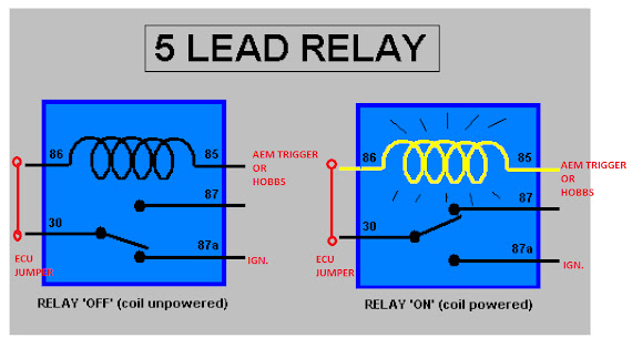
As another data point try measuring the resistance of this pin in the wiring harness to ground (CDI unplugged). You should get around 150 ohms.
Just for informational purposes this is a graphic display of what the voltage should be on that pin:
http://i397.photobucket.com/albums/pp60/LynnEdwards_photo/1jpg.jpg
The relatively long periods of zero volts between pulse pairs is why you read much less than the 5 volt peaks.
The trigger pickup coil is outside the flywheel, but under the engine cover. On some quads the gap between the pickup coil and the flywheel is adjustable. You might want to see if yours is adjustable, and then try narrowing the gap. That will increase your trigger voltage substantially. I have read posts from others who have solved their no spark problem by narrowing this gap.
Also make sure that the connection from the CDI output through the ignition coil primary is OK. Measure the resistance from the Ignition Coil pin in the wiring harness to ground. You should get around 1-2 ohms. You should not get zero ohms.
Measuring resistance on the timing trigger and ignition coil pins on the harness, I get 0.5 ohms on both of them.
LynnEdwards
12-05-2009, 01:32 AM
...The power supply voltage to the CDI, measured when cranking, is around 46 volts, could be more if the battery is fully charged. Timing trigger registers 5.3 volts, and a resistance test on this pin is 0.5 ohms. Ground pin checks ok, kill switch checks ok, and the ignition coil pin shows no voltage....
Two problems:
1) 0.5 ohms on the timing trigger pin is way too low. It should be more like 150 ohms.
2) 5.3 volts AC on the trigger pin is way too high. It should be more like 0.3 to 0.5 volts AC
Down around your stator there is a group of wires that come out of the engine (from the stator) and tie into the wiring harness. Is there any possibility that these may have been miswired recently?
Measure the resistance of all the wires to ground at the stator output connector(s).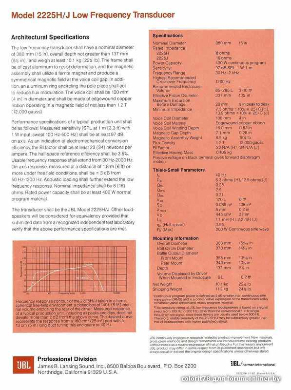 Do any of them read around 150 ohms?
What I'm wondering is if the battery charge winding in the stator is wired to the trigger input of the CDI. It's resistance and output voltage at cranking speeds is a lot closer to what you measured for the trigger pin then the expected trigger voltage and resistance.
You may want to measure the trigger voltage and resistances again just to be sure you get the same values. And remember that the picture of the CDI pins is mirror imaged from the mating pins in the wiring harness since you have to flip the connector over to look into the pins.
TallGuy
12-05-2009, 11:23 AM
As for the measurements, I double checked and still have the same thing.
The 3 wires coming out of the stator, a couple of them are very small in resistance, around 0.5 ohms, the other is around 330 ohms.
As for messing up a wire - it's possible. The 4 wheeler ran fine, then one day it had power issues, so I jiggled the wires around and checked all the connections. Possibility that I got one wrong, I don't know - it's been 6 months since I fixed that issue, and just haven't gotten around to fixing the spark problem. That power problem was at the fuse, just a bad connection.
TallGuy
12-05-2009, 01:25 PM
Lynn, I and my kids very much appreciate your help. With your insight, I pulled the stator off and traced where the timing trigger wire was going. Come to find out two of the wires WERE backwards. After moving them to the proper place, I have a spark.
Now to try adjusting the carburetor so I don't have to crank it for 15 minutes in the cool air to start it. I think I'll clean up the wiring too. :wink:
Thank you!
LynnEdwards
12-05-2009, 11:03 PM
TallGuy, I'm glad you were able to find the problem. :lol:
bigbadbob17
08-14-2011, 07:38 PM
first off, this forum has a tonne of great info!!
I purchased a gio 110 mini hummer the other day, I drove it around the yard for probably 10 rides without an issue, parked it by the front door and came inside. Went back out an hour later and it wont start! Tested the CDI, AC ignition power is within range, timing trigger is within range, CDI is grounded, kill switch ruled out but I have 0 volts on the ignition coil wire when I turn the engine over, does this mean a bad CDI??
vBulletin® v3.8.4, Copyright ©2000-2022, Jelsoft Enterprises Ltd.
The ignition system must provide a spark of sufficient intensity in the right cylinder at the right time thousands of times per minute. Therefore, the correct repair of the ignition system is an urgent need. With our ignition coil maintenance tips, you'll learn how they work, why they fail, what indicates they're bad, and how to replace them to provide a high-quality, durable repair that you and your customers can trust.
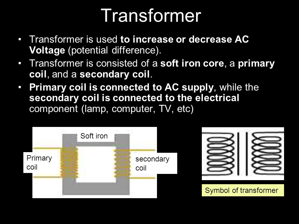
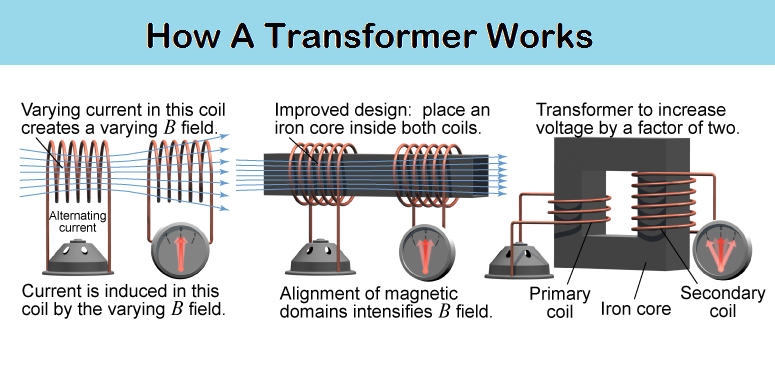
For ignition to occur, a spark is needed to ignite the air/fuel mixture in the engine. This is the function of the ignition coil.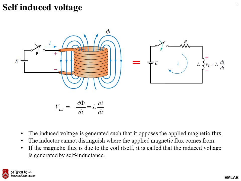 It is an electrical transformer that converts low battery voltage - usually only 12 volts - to very high voltage in order to spark a spark in the gap of the spark plug, igniting the fuel. As a result, the engine starts. Some systems require only one coil, but most newer vehicles have a separate ignition coil per cylinder.
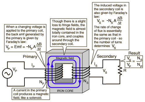
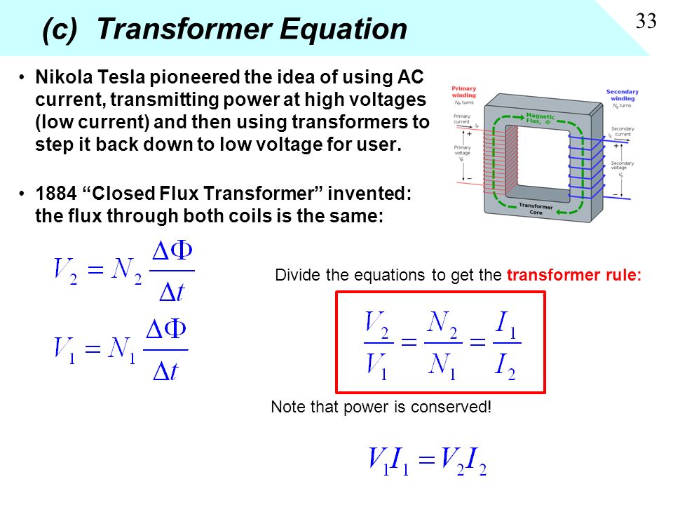
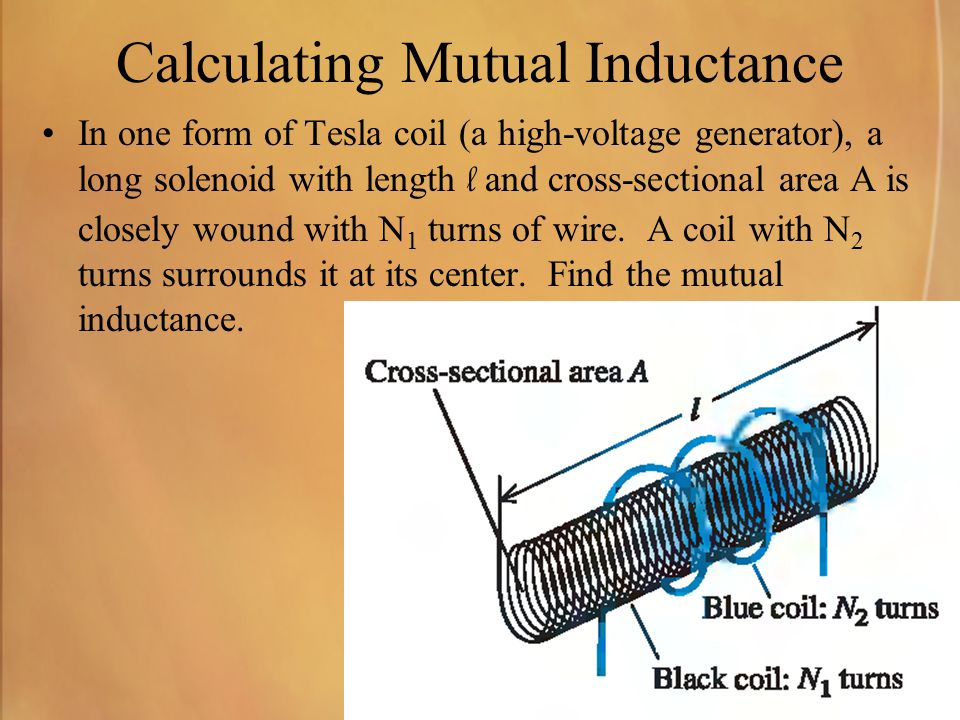
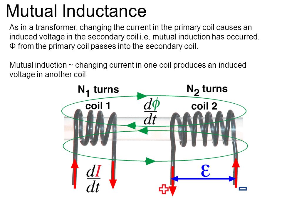
In simple terms, ignition coils consist of three parts: a primary circuit consisting of a few hundred turns of the primary winding, a secondary circuit consisting of a few thousand more turns, and an iron core. When current flows through the primary circuit, a powerful magnetic field is created around the core, charging the coil. However, when the power supply is interrupted, the magnetic field disappears. And since this energy has to go somewhere, it induces a pulse of current in the secondary coil, increasing its voltage until there is enough of it to create an ignition spark.
The required voltage can vary from as little as 5,000 volts to 25,000 volts and is dependent on a number of factors such as spark plug gap width, spark plug electrical resistance, air-fuel ratio, spark plug temperature, engine load, etc.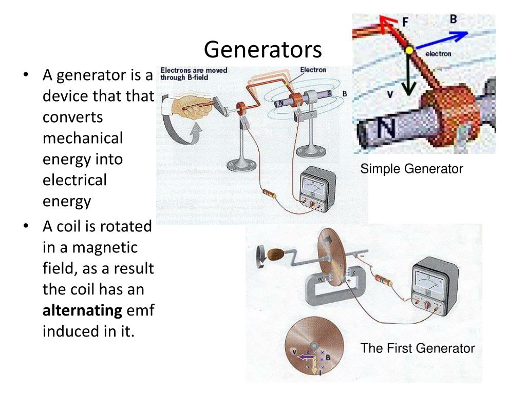 In fact, at maximum load, some systems require up to 40,000 volts. The magnitude of the output voltage is determined by the ratio of the number of turns of the secondary winding to the number of turns of the primary winding, which is usually on the order of 80 to one, but the higher this ratio, the higher the potential voltage.
On older vehicles, the ignition coil is located between the battery and the distributor. However, in modern electronically controlled ignition systems, a distributor is no longer needed. Instead, the operation of the spark plugs is controlled by the engine control unit (ECU). Thus, in systems with individual ignition coils, the coils are mounted directly above each spark plug. Or in the case of distributorless systems with an "idle spark", they are connected to a pair of spark plugs.
Because of this, the number of coils can also vary. While older systems typically use a single coil, more modern vehicles have multiple coils, one per cylinder or each pair of cylinders. This allows car manufacturers to more accurately control ignition timing, improve engine performance, and reduce fuel consumption and emissions.
Although ignition coils are built to last, increasing demands on them mean they can fail. Among the main reasons for their breakdown are the following:
 It can also loosen the electrical connector connected to the spark plug, causing the ignition coil to do extra work to create a spark.
  In both cases, in order to avoid repeated similar breakdowns, it is important to eliminate the root cause of the malfunction.
 Since the ignition coil is responsible for generating the spark that starts the car's engine, any failure of the ignition coil will quickly affect engine performance. The following signs of a malfunction of the ignition coil can be distinguished:
If a faulty ignition coil is suspected, to simplify the diagnostic process, simply follow the steps below:
Once the fault has been identified, replace the ignition coil by following the simple steps below:
More about ignition coils.
 ru
ru 01/22/2020
Ignition system.
Lynx snowmobile has a simple ignition system. It is an electronic ignition that consists of a magdino, an ignition switch, an ignition coil, high voltage wires, spark plugs and spark plug caps.
Consider the ignition system produced by the Moscow company "Flames".
Magdino 26.3749
Consists of a silumin housing, 3 lighting coils and ignition coils are located on the housing. There is a signal coil winding and a switch power coil winding. There are 2 white wires coming from the lighting coils connected in series, they are connected to the snowmobile's lighting system.
To do this, Flames produces a voltage regulator 304.3702.
The cable of the engine ignition system comes out from the magdino, which consists of 3 wires - red, black and yellow. The red and black wires come out of the coil and supply AC voltage to the ignition switch. The yellow wire comes out of the blue one. The black wire is common to both coils.
The signal of the ignition coil at idle and at high speeds has different forms:
Ignition coil signal at engine idle.
Signal from the ignition coil at high speeds
/3 on the right. This position will provide the owner with accurate ignition timing without additional installation using a stroboscope.
Switch 84.3734-01.
The switch has 5 colored wires on the terminals. Red and black are connected to the switch power coil. The green (yellow) wire connects to the yellow (green) wire that comes out of the magdino harness. The blue wire connects
to the input of the ignition coil. White wire connects to
snowmobile ground. The algorithm of the switch operation includes the formation of the ignition advance angle of the switch operation and is maintained automatically.
Ignition coil 3012. 3705.
3705.
Dry coil, two-terminal, sealed with compound. The coil was used on injection engines ZMZ-406. People call it "Volgovskaya coil". This coil is recommended by the manufacturer for Flames ignition. Many "specialists" say that coils do not make a difference and any TLM-1, TLM-2, TLM-3, 4412.3705, 406.3705 and others can be connected to ignite a snowmobile. These coils have parameters that do not meet Flames' ignition design parameters. The ignition coil 3012.3705 is installed in the Flames ignition system. Without going into the details of the processes, we will touch upon one of them superficially and try to talk about it. Ignition coils have a transformer design, the task of the coil is to increase the signal voltage from the switch to the required breakdown voltage of the air gap on the spark plug to ignite the air-fuel mixture in the engine combustion chamber. Entering the primary winding of the ignition coil, the voltage of the order of 22-28 volts rises to 25-30 kilovolts. The voltage is stored in the coil and part of this voltage is returned to the switch.
Switch output stages bypass this voltage. Ignition coil voltage 3012.3705 is the lowest. The output stages of the switch cope with it without failing. With ignition coils of other brands, the parasitic voltage is high and in some cases disables the switch. Using ignition coils not recommended by the manufacturer, the owner risks a sudden failure of the ignition system. The failure of the ignition system can lead to very unpleasant consequences. On a snowmobile, you can go very far in a few minutes, and you will have to return through deep snow for a very long time.
High voltage wires.
Few people take this issue seriously, but ignition and engine malfunctions can occur in high-voltage wires. High-voltage wires must have a copper core that does not have electrical resistance.
Some install high-voltage car wires, with silicone or multi-layer insulation.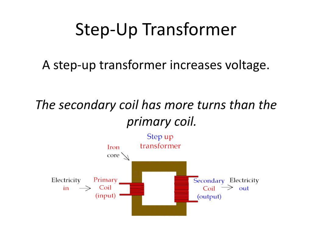 The conductors in such wires are often constructed from nichrome, manganin, or carbon fiber conductors. These wires have, as a rule, an electrical resistance of the order of 8 kilo-ohms. The high-voltage wires in the ignition system of the Lynx snowmobile with Flames ignition are used with copper stranded wire, which has no resistance to electrical voltage.
Spark plug caps.
The spark plug cap is important when choosing an ignition element. There is a fairly large selection of an element of the Lynx snowmobile engine ignition system on sale. It must be borne in mind that two systems are implemented in the caps, with and without a resistor. The spark plug cap, which contains resistance in its design, has a rating of 4.7 to 5.6 kOhm. This is necessary for the formation of a spark discharge in the spark plug. There is an erroneous opinion that it is necessary that there is no interference in electrical appliances, that by removing the resistance from the sparking system, there will be more sparks and the snowmobile will become faster, this is a complete ignorance of electrical engineering, this action will lead to a violation of the ignition of the fuel.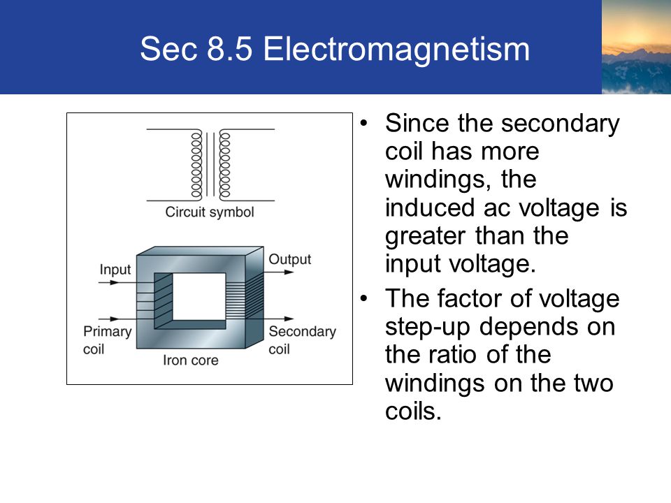
Spark plug.
Spark plug NGK B9ES without resistor It must be installed in the snowmobile engine, it must meet the following parameters: glow number - 23 (cold plug), thread diameter 14 mm, hex key size - 20.8 mm, thread length - 19 mm, the central insulator must not protrude over the edge of the thread (must be inside). The gap between the electrode should be 0.5-0.6 mm. Consider electronic resistance. If the cap contains resistance (resistor), then the candle should not contain a resistor. If the cap does not have a resistor, the resistor must be in the spark plug. When choosing spark plugs, you need to know this
Consider what resistance is needed in a sparking system
Consider a simulated graph in a sparking system.
A - ignition coil charging time. B is the breakdown impulse. B is the burning time of the spark arc.
Breakdown occurs when the coil primary circuit is opened.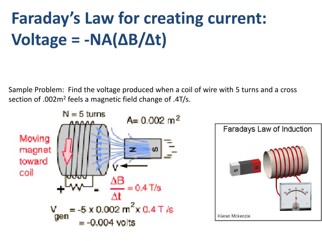 If this happens, a self-inductive voltage will appear on the secondary winding, which will lead to a rapid increase in voltage. The voltage will increase until it exceeds the air gap breakdown voltage. Plot "A". The duration of the breakdown is about 10-20 microseconds. Plot "B". The next section "B" represents the burning of a spark arc or the flow of direct current in the gap of the candle. The burning voltage is 1-2 kV. The energy in the coil is used to break through the spark plug gap and to keep the spark burning. The higher the breakdown voltage, the shorter the duration of the spark, the ignition of the fuel will be worse, there may be no ignition, and vice versa, with a low breakdown voltage, the burning time increases, but this indicates a small gap of the spark plug and a decrease in the interaction of the spark with the fuel mixture, which also leads to to a small probability of ignition of fuel.
The ignition switch generates a negative signal with a voltage of 22-28 V with a signal repetition rate of 38-42 ms.
Commutator Signal Graph
The signal following time is sufficient to accumulate voltage by the ignition coil, break down the air spark gap and maintain the spark arc. If there is a resistance of 5.6 kΩ on the way from the ignition coil to the air gap of the spark plug, the ignition coil accumulates enough energy (section "A"), while forming a breakdown voltage of 25 kV (section "B") and maintaining the burning time of the spark arc 2 -2.5 ms (section "B"). The resistance lowers the breakdown voltage to 25 kV and at this time gradually releases the stored energy to the coil and maintains the spark arc burning for 2-2.5 ms.
If there is no resistance, the graph will look like this:.
The breakdown voltage is higher, about 34-37 kV. There is no spark-arc maintenance mode. The process of ignition of the mixture is limited to non-falling from the section "B". Ignition of the mixture is problematic and will not take place completely due to the lack of a spark burning area.
Consider the case where a snowmobile owner, based on poor judgment, installs inappropriate components such as silicone wires (8 kΩ), resistance caps (4.7 kΩ), and spark plugs (5.6 kΩ). As a result, we get about 16-20 kOhm.
The sparking graph will look like this:
Comments do not inspire confidence in high-quality ignition. Sparking is low, combustion is maintained, but with a falling and very low level, this is not enough to ignite the mixture.
Incompletely combusted air-fuel mixture results in large amounts of carbon deposits, engine knocking, carbon deposits in the exhaust, leading to carbon deposits in the resonant tube and changing exhaust design parameters. This will result in loss of power, inability of the snowmobile to reach high engine speeds, ignition of the exhaust mixture in the resonant tube, burnout of the exhaust manifold, resonant tube and piston. Violation of the thermal balance of the engine and overheating. Misfires.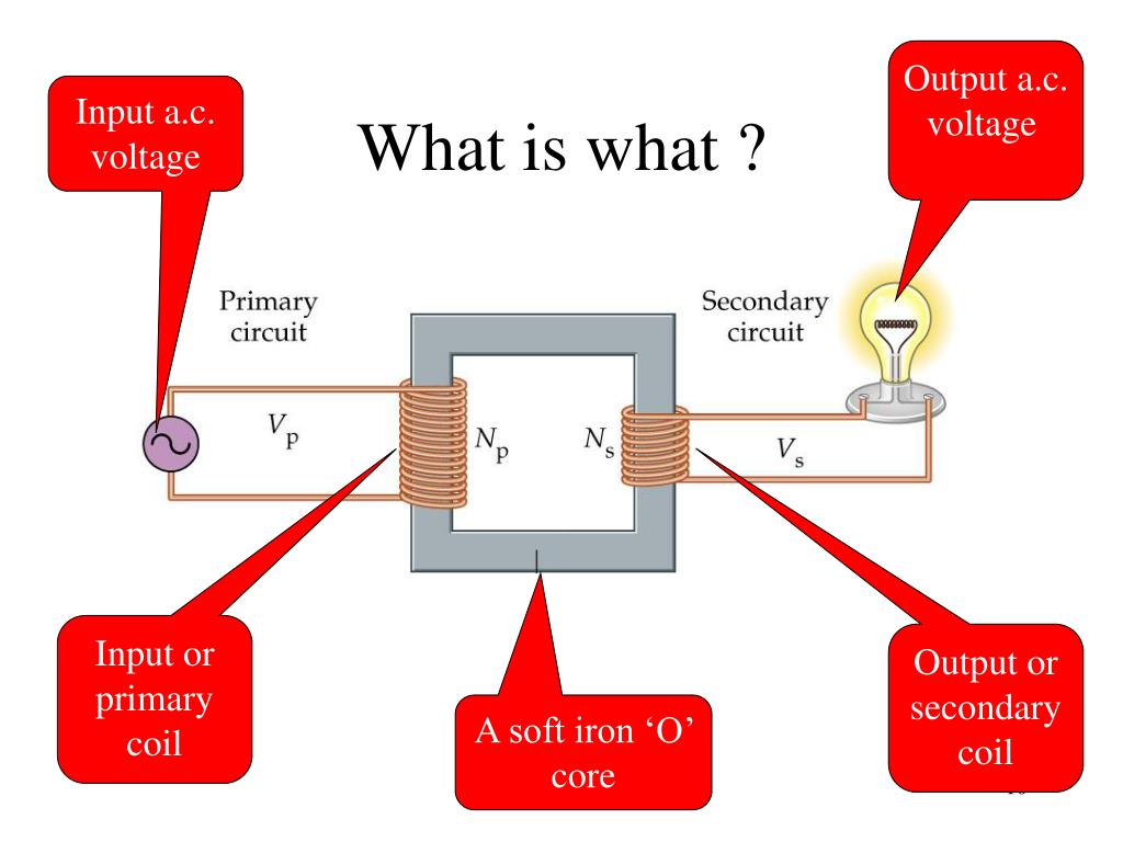
This is how the misfiring graph looks like:
Please note that UMPO produced two versions of crankcases, the main difference is the mounting of the base of the magdino, as well as the flywheel itself.
The photo shows which flywheel should be when attaching the base of the magdino to the crankcase.
Lynx snowmobile crankcase and flywheel of the first years of production
Lynx snowmobile crankcase and flywheel
. The most common sign that you have the wrong flywheel is that the engine starts in reverse st
shut down or not start at all.
There were crankcases on which ebbs were located for both options for the location of the base of the magdino.
If you cannot replace the flywheel, you will have to change the beginning and end of the charge coil windings, the red and black wires in the plug and the beginning and end of the sensor winding. To do this, you need to bite the petal of the negative conductor coming out of the coil, without unscrewing the screws securing the coils, solder the wire and lead it to the green wire of the switch 84.