The force that resists the motion of a body rolling on a surface is called the rolling resistance or the rolling friction.
The rolling resistance can be expressed by the generic equation
Fr = c W (1)
where
Fr = rolling resistance or rolling friction (N, lbf)
c = rolling resistance coefficient - dimensionless (coefficient of rolling friction - CRF)
W = m ag
= normal force - or weight - of the body (N, lbf)
m = mass of body (kg, lb)
ag = acceleration of gravity ( 9.81 m/s2, 32.174 ft/s2)
Note that the rolling resistance coefficient - c - is influenced by different variables like wheel design, rolling surface, wheel dimensions and more.
The rolling resistance can alternatively be expressed as
Fr = cl W / r (2)
where
cl = rolling resistance coefficient - dimension length (coefficient of rolling friction) (mm, in)
r = radius of wheel (mm, in)
Some typical rolling coefficients:
| Rolling Resistance Coefficient | ||
|---|---|---|
| c | cl (mm) | |
| 0. | 0.5 | railroad steel wheels on steel rails |
| 0.001 | bicycle tire on wooden track | |
| 0.002 - 0.005 | low resistance tubeless tires | |
| 0.002 | bicycle tire on concrete | |
| 0.004 | bicycle tire on asphalt road | |
| 0.005 | dirty tram rails | |
| 0.006 - 0.01 | truck tire on asphalt | |
| 0.008 | bicycle tire on rough paved road | |
| 0.01 - 0.015 | ordinary car tires on concrete, new asphalt, cobbles small new | |
| 0.02 | car tires on tar or asphalt | |
| 0.02 | car tires on gravel - rolled new | |
| 0.03 | car tires on cobbles - large worn | |
| 0.04 - 0.08 | car tire on solid sand, gravel loose worn, soil medium hard | |
| 0.2 - 0.4 | car tire on loose sand | |
The rolling coefficients for air filled tires on dry roads can be estimated
c = 0. 005 + (1 / p) (0.01 + 0.0095 (v / 100)2) (3)
where
c = rolling coefficient
p = tire pressure (bar)
v = velocity (km/h)
The standard wheel pressure in a Tesla Model 3 is 2.9 bar (42 psi). The rolling friction coefficient at 90 km/h (56 mph) can be calculated from (3) as
c = 0.005 + (1 / (2.9 bar)) (0.01 + 0.0095 ((90 km/h) / 100)2)
= 0.011
Increasing the pressure to 3.5 bar reduces the rolling resitance coefficient to
c = 0.005 + (1 / (3.5 bar)) (0.01 + 0.0095 ((90 km/h) / 100)2)
= 0.010
- or
((0.011 - 0.10) / 0.011) 100% = 9%
The rolling resistance for all four wheels in a car with total weight 1500 kg on asphalt with rolling friction coefficient 0. 03 can be estimated with the generic equation 1 as
Fr = 0.03 (1500 kg) (9.81 m/s 2)
= 441 N
= 0.44 kN
The rolling resistance for one wheel can be calculated as
Fr = 0.03 (1500 kg / 4) (9.81 m/s2)
= 110 N
= 0.11 kN
Rolling resistance is the resistive force applied to the wheel when it’s rolling. The magnitude of rolling resistance depends on a series of factors, which most of the time act together and can not be broken down clearly.
Most common causes of rolling resistance applied to a wheel in motion are:
In the following discussion we are going to focus on the rolling resistance caused by the tire and road. The wheel hub and bearings efficiency is not part of this lecture since they can be consider as part of the overall driveline losses (efficiency).
Image: Tire pressure distribution – stationary vs. rolling
In the image above: N [N] – normal reaction force, W [N] – weight force acting on the wheel and ω [rad/s] – angular speed of the wheel.
When the tire is stationary, the distribution of the normal force N [N] in the contact patch is symmetric with respect with the vertical axis of the wheel. However, when the wheel is in motion (rotating), the normal force distribution is not anymore symmetric but concentrates in the front of the wheel, towards the direction of motion. This makes the resultant force N [N] to create a resistive rolling torque, which will try to slow down the wheel.
Go back
Image: Rolling resistance – wheel forces diagram
Let’s assume we have a vehicle which has front-wheel drive (FWD). The rear wheels are going to be pulled along, through the chassis. Therefore there will be a pulling force Fp [N] acting in the wheel hub, which will force the wheel to rotate. As explained previously, due to asymmetric force distribution in the contact patch, there is going to be a normal force N [N] acting on the tire, at the distance a [m] from the vertical axis of the tire.
The force N [N] is the vertical component of a resultant force going through the tire’s centre of rotation. The horizontal component of that resultant force, acting in the contact patch, which is trying to slow down the tire is exactly the rolling resistance force Frr [N].
Since the wheel is in equilibrium, the sum of forces on the x-axis, the sum of forces on the y-axis and the sums of torques acting around the centre of the wheels are all zero.
ΣFx = 0
(1)
Fp – Frr = 0
(2)
Fp = Frr
(3)
ΣFy = 0
(4)
N – W = 0
(5)
N = W
(6)
ΣT = 0
(7)
Frr · rw – N · a = 0
(8)
Replacing N from (6) in (8) and solving for Frr [N] gives:
Frr = (a/rw) · W
(9)
The ratio between distance a [m] and wheel radius rw [m] is the rolling resistance coefficient f [-].
f= a/rw
(10)
Replacing (10) in equation (9) gives the general formula of the rolling resistance force for flat (no gradient) roads.
Frr = f · W = f · m · g
(11)
where m [kg] is the vehicle mass and g = 9.81 m/s2 is the gravitational acceleration.
If we calculate the total rolling resistance force of the vehicle, then the entire vehicle mass is used in the equation. If we calculate the rolling resistance of only one wheel, then the vehicle mass is divided by four (assuming equal weight distribution between wheels).
If the vehicle is rolling on a road with the gradient α [°], then the formula for rolling resistance becomes:
Frr = f · W · cos(α) = f · m · g · cos(α)
(12)
Go back
The rolling resistance coefficient of a tire depends on tire construction, materials, air pressure, vehicle speed, and road conditions. In general, for low vehicle speeds, the value of rolling resistance coefficient is constant.
The rolling resistance coefficient slightly increases with the increase of the traveling speed of the vehicle. According to [7], under normal operating conditions, with the vehicle speed below 200 kph, the rolling resistance coefficient is between 0. 01 – 0.02.
There are several sources of automotive literature, in which you can find the value of the rolling resistance coefficient, function on several parameters. For example in [6], you can find the value of the rolling resistance coefficient function of the road type.
| Road surface | Rolling resistance coefficient |
| Pneumatic car tires on | |
| large set pavement | 0.013 |
| small set pavement | 0.013 |
| concrete, asphalt | 0.011 |
| rolled gravel | 0.02 |
| tarmacadam | 0.025 |
| unpaved road | 0.05 |
| field | 0.1 – 0.35 |
| Pneumatic truck tires | |
| on concrete, asphalt | 0.006 – 0.01 |
| Strake wheels in field | 0.14 – 0.24 |
| Track-type tractor in field | 0.07 – 0. 12 12 |
| Wheel on rail | 0.001 – 0.002 |
Table: Coefficients of rolling resistance
Source: [6]
From [1] we can also extract a table of rolling resistance coefficients function of road surface.
| Road surface | Rolling resistance coefficient |
| new, firm asphalt; concrete; small pavement; cobblestone pavement | 0.005 – 0.015 |
| rolled, firm gravel; wear down, washboard asphalt | 0.02 – 0.03 |
| tarred, wear down, washboard gravel | 0.03 – 0.04 |
| very well dirt roads | 0.04 – 0.05 |
| dirt roads | 0.05 – 0.15 |
| sand | 0.15 – 0.35 |
Table: Coefficients of rolling resistance
Source: [1]
Additional values for the rolling resistance coefficient can be found in [8] for different pavement types at low vehicle speeds.
| Pavement type | Rolling resistance coefficient |
| Good asphalt or concrete pavement | 0.01 – 0.018 |
| General asphalt or concrete pavement | 0.018 – 0.02 |
| Gravel road | 0.02 – 0.025 |
| Good gravel road | 0.025 – 0.030 |
| Pebble potholes pavement | 0.035 – 0.050 |
| Pressed dirt road (dry) | 0.025 – 0.035 |
| Pressed dirt road (rainy) | 0.050 – 0.150 |
| Muddy dirt road | 0.100 – 0.250 |
| Dry sand | 0.100 – 0.300 |
| Wet sand | 0.060 – 0.150 |
| Icy roads | 0.015 – 0.030 |
| Compacted ski track | 0.030 – 0.050 |
Table: Rolling resistance coefficient of a vehicle at low speed on a given road
Source: [8]
In reality, the rolling resistance coefficient depends on several factors, like:
In the image below you can see the influence of tire pressure on the rolling resistance coefficient.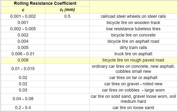 As the air pressure increases, the rolling resistance coefficient decreases. This happens because an increased internal pressure leads to a further stiffening of the tire, which means that the tire deflection decreases at steady state load. This leads to a decrease of the tire flexing energy and due to the smaller contact patch, to a decline of the frictional component of resistance [1].
Image: Rolling resistance coefficient function of wheel load and tire pressure
Credit: [1]
In the next image you can see the influence of vehicle speed on the rolling resistance. The increase of the rolling resistance coefficient, which rises with the vehicle speed is due to the superimposed effect of the tire deformation wave on the flexion resistance. This effect increases with velocity [1].
Image: Rolling resistance coefficient function of driving speed
Credit: [1]
Go back
For calculation/simulation purposes, you can use either a constant value of the rolling resistant coefficient or a speed dependant one.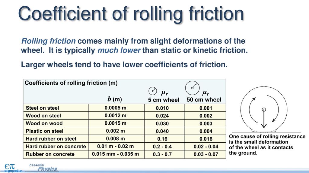 {2} \tag{13}\]
where V [kph] is vehicle speed and f0, f01 and f02 are coefficients function of tire construction. For example, for a radial tire, the coefficients can be set as:
f0 = 1 · 10-2
f01 = 5 · 10-7
f02 = 2 · 10-7
If we plot f [-] function of V [kph], we get the following curve:
Image: Rolling resistance coefficient (1)
The coefficients can be adjusted in order to obtain the desired behaviour of the rolling resistance coefficient. For a road made from good asphalt or concrete, a rolling coefficient which varies between 0.01 at 0 kph and 0.025 at 250 kph is good enough for simulations.
Go back
Once we have the rolling resistance coefficient function of vehicle speed, we can apply equation (12) and get the rolling resistance force.
For example, if we consider that the total mass of the vehicle is 2000 kg and that the weight is evenly distributed on all four wheels, we’ll get a weight on a wheel of:
Frr = (2000/4) · 9.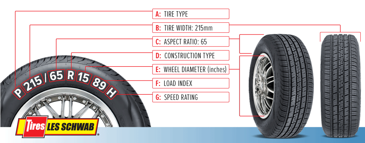 81 · f(V)
(14)
Applying equation (12) and the rolling resistance coefficient defined by (13), we can plot the rolling resistance force function of vehicle speed.
Image: Rolling resistance force function of speed
In the SAE standard J2452, the rolling resistance force is defined function of vehicle speed, tire inflation pressure and the load applied on the wheel.
Frr = Zα · Pβ · (a + b · V + c · V2)
(15)
where:
Frr [N / lbs] – rolling resistance force
P [kPa / psi] – tire inflation pressure
Z [N / lbs] – tire load
V [kph / mph] – vehicle speed
α, β, a, b, c [-] – tire dependant coefficients
As an example, from [3] we can extract the coefficients for the tire T40 of size 205/75R15 97S:
α = 1.03399904
β = -0.41081927
a = 0.05933157
b = 9.85526e-05
c = 3.72314e-07
For the same tire load of 4905 N and different inflation pressures of 150, 250 and 350 kPa, we can plot the rolling resistance using equation (15):
Image: Rolling resistance force function of speed pressure and load
Go back
For a vehicle of mass 1800 kg, travelling on a road with the slope angle of 10° and with a fixed rolling resistance coefficient of 0. 012, calculate the total rolling resistance force.
Applying equation (12), we get:
Frr = 1800 · 9.81 · 0.012 · cos(10 · π / 180) = 209 N
Go back
| m [kg] = | f [-] = | α [°] = |
| Frr [N] = | ||
Go back
[1] Henning Wallentowitz, Longitudinal Dynamics of Vehicles – Lecture, IKA RWTH, Aachen, 2004.
[2] Lars Eriksson, Lars Nielsen, Modeling and Control of Engines and Drivelines, Wiley, 2014.
[3] Ben Wen, Gregory Rogerson, and Alan Hartke, Correlation Analysis of Rolling Resistance Test Results from SAE J1269 and J2452, SAE International, 2014.
[4] Green Seal’s Report, Low Rolling Resistance Tires, March, 2003.
[5] Transportation Research Board, Tires and Passenger Vehicle Fuel Economy, Transportation Research Board Special Report 286, 2006.
[6] Automotive Handbook, 9th Edition, Bosch, 2014.
[7] Georg Rill, Vehicle Dynamics – Lecture Notes, University of Applied Sciences, Regensburg, 2005.
[8] Wuwei Chen et al, Integrated Vehicle Dynamics and Control, Wiley, 2016.
[9] M. Untaru et al, Dinamica Autovehiculelor pe Roti, Editura Didactica si Pedagogica, Bucuresti, 1981.
Few of the motorists paid due attention to such characteristics of tires as tire rolling resistance. But in vain. Car tires are such a complex technical element that not only the patency and driving safety, but also fuel economy depend on it. In this case, both car owners and environmentalists benefit, since the reduction in exhaust gases leads to a lesser degree of anthropogenic pollution of the environment.
To explain briefly and intelligibly what the rolling resistance of a wheel is, it is necessary to imagine a tire in the contact patch with the road. At this point, the rubber expands under the load of the machine. Together with the inertia of the car, the rubber heats up and wastes part of the energy transmitted from the motor, this phenomenon is called tire rolling resistance. It is measured by the formula Pf \u003d Q x f, where "Q" is the normal load of the car, and "f" is the coefficient of rolling friction.
For each road surface, the coefficient "f" has its own value, for example, for asphalt concrete 0.01, and for gravel 0.025. In total, 6 values of "f" are used to calculate the formula for wheeled vehicles. All values and names of coatings can be found in the corresponding table.
In motion, the tire is subject to numerous loads and deformations. All of them affect the degree of rolling resistance of the tire. These loads include:

If the vehicle hits a bump at low speed, it is able to stop. To create kinetic energy to overcome an obstacle, it is necessary to provide the car with a higher speed, and this is additional energy from the internal combustion engine.
The degree of tire rolling resistance phenomenon depends on many factors. Among the most famous are such as:
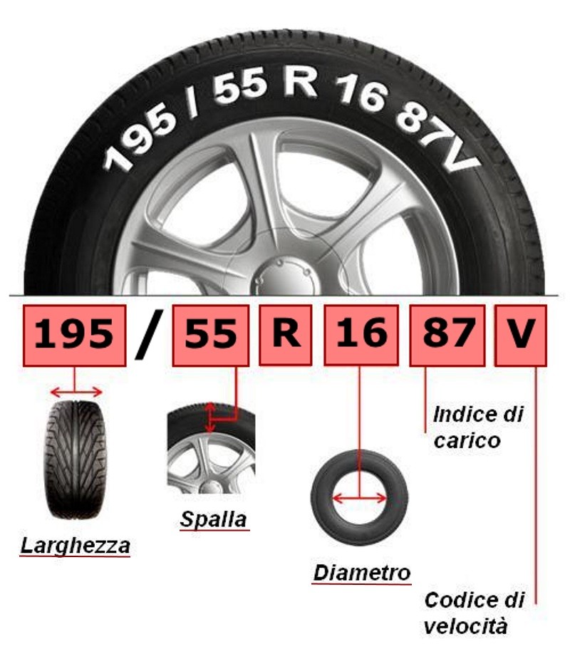 For each additional 1 cm of radius, the degree of resistance is reduced by 1%;
 In light of the ongoing fight for the environment, many tire manufacturers have joined the environmental movement. This was manifested in the development of "green" tires produced since 1992 years old Gradually, the characteristics of the wheels increase. The meaning of "green" tires is that a car "shod" in rubber with reduced rolling resistance consumes less fuel, by about 20%. Thus, a smaller number of harmful substances contained in the exhaust gases enter the atmosphere.
According to research, every 45,000 runs on tires with low rolling resistance, owners save an amount equal to ¼ of the cost of the entire set of wheels. In addition to saving, drivers pollute the air less, making a personal contribution to the environment, taking care of their offspring. To inform the buyer, the manufacturer puts the appropriate markings on the side profile of the rubber: Green X or Reduces CO2.
The invention relates to the field of testing vehicle tires. At least one mark is installed on the drum of the stand. On the fixed part of the stand, a speed sensor that reacts to it is fixed, according to the signals of which time marks are made, and connected to the recording device. The value of rolling resistance is judged by the ratio between the number of revolutions of the drum, made from some instantaneous value of time to stop, and the values of the time of their completion. The same sensor signals are used to measure the drum revolutions and the corresponding overrun time. As a result, the measurement accuracy is improved. 1 z.p.f-ly, 3 ill.
The technical solution relates to the field of vehicle tire testing and can be used to determine the rolling resistance of tires in laboratory conditions on drum stands using the coast down method (damped motion by inertia).
Known methods for determining the rolling resistance of wheels with elastic tires on drum stands by the coast method [1, 2], in which the moments of inertia of the running drum of the stand and associated rotating parts of its drive are determined, as well as the moments of inertia of the wheel (s) with the tested tires , then install the tested tire (tires) on the stand, press it against the drum with normal force, create the required internal pressure and temperature in the tire and accelerate the "stand-tire" system to the set speed, after which the power drive of the stand is turned off (for example, by turning off the electric motor of the stand both from the network and from electrodynamic braking systems).
A common feature of all known methods of this kind is the determination of the deceleration of the "stand-tire" system during free run-out, by the value of which, multiplied by the reduced moment of inertia of the system, one judges the resistance to its movement. Next, the stand drum with the drive is run out with the tire removed from contact with it and the stand drive losses are determined, subtracting which from the previously obtained resistance to movement of the "stand-tire" system, the actual rolling resistance of the tire along the drum is obtained. In turn, the deceleration during the free damped movement of the stand in the known methods is determined by the ratio V of the accepted interval for reducing the speed of the tire rolling on the drum to the value t of the time interval during which this decrease occurs. Since the speed, as is known, cannot be measured directly, requiring additional measurements of the path S and approximate calculations using the formula V = S/t, this is a source of significant errors in determining the rolling resistance. A significant disadvantage of the known varieties of the run-down method in relation to drum stands is that in the interval V of the speed reduction it is assumed to be linearly dependent on time, although in reality the corresponding dependence is essentially non-linear. This introduces significant errors in the determined values of the deceleration j, which are assumed to be equal to j = V/t. There is also known a method for determining the resistance to movement of a wheel with a car tire by the coast down method [3], taken as a prototype, in which the measurement of the time interval during which the speed decreases by V is performed with a stopwatch, which is turned on and off at the boundaries of the period by interrupting the light beam falling on the light receiver, for which purpose a screen is installed on the arrow of the device - the speed indicator for the angular overlap of the beam corresponding to the value V, tracked by the arrow of the device - the speed indicator.
The main disadvantage of this method is the already noted above need to measure the tire rolling speed on the drum, as well as the measurement errors of the interval V, associated with errors in the relative position of the light beam source and the screen covering the zone V.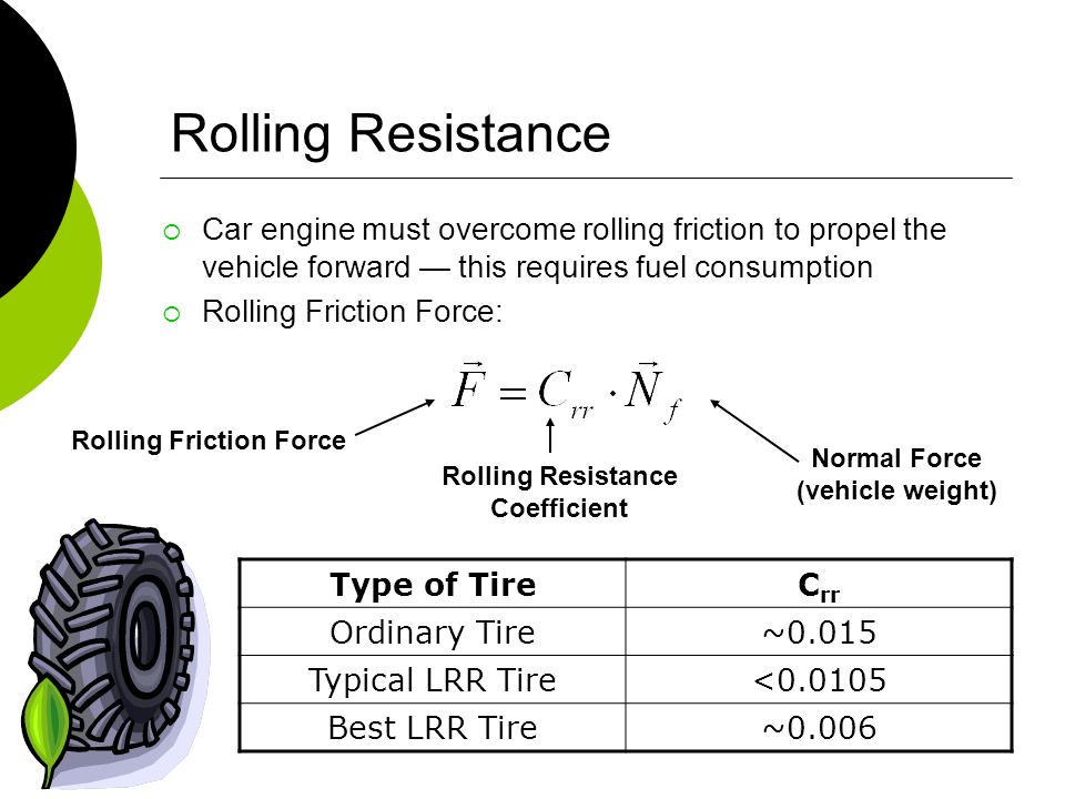 In addition, each of the described measurements must be made for each of the selected tire rolling speeds on the drum. Taken together, these error sources significantly reduce the accuracy of rolling resistance measurements, which are small values that manifest themselves under conditions of high values of normal tire loads.
The problem to be solved is to increase the accuracy and sensitivity of the method by eliminating the need to measure the rolling speed as a source of a whole group of measurement errors.
To solve this problem, at least one mark is installed on the drum of the stand, a speed sensor that responds to it is fixed on the stationary part of the stand, according to the signals of which time marks are made, the speed sensor is connected to a device that registers the number of revolutions and the corresponding time values, and the value of rolling resistance is judged by the ratios between the numbers of revolutions of the drum made from some instantaneous value of time to stop and the values of the time of their completion, and the same sensor signals are used to measure the numbers of revolutions of the drum and the corresponding run-out time.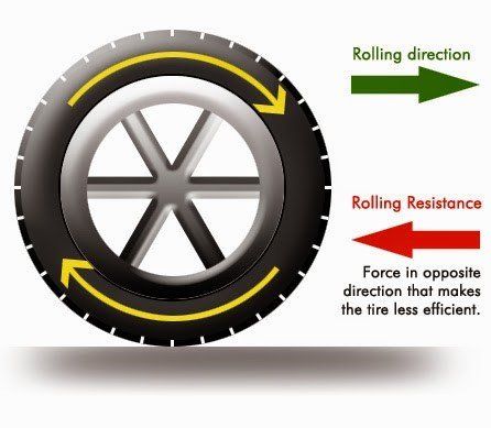
If the number of marks on the drum is limited to one or two, then the ratios between the numbers of drum revolutions and the corresponding values of the run-out time are grouped in pairs and the ratios of the differences in the numbers of drum revolutions between each two time values are used.
Fig. 1 shows a diagram of the installation of a sensor, a mark in the form of a reflector and a recording device on a drum tire test stand.
Fig. 2 shows the scheme for registering run-out parameters.
FIG. 3 - the same, for the case of pairwise grouping of the ratio of the numbers of revolutions of the drum and the corresponding values of the run-out time.
The method for determining the rolling resistance of a wheel with an elastic tire is as follows. On the drum 1 of the stand (Fig. 1), on which the tire 2 is tested, at least one mark 3 is installed, which can be a fragment of a reflective tape or reflective tape of limited size, and a speed sensor 4 responsive to such a mark is fixed on the stationary part of the stand , which is used, for example, a photoelectric sensor of visible red or infrared radiation. The sensor 4 is connected to the recording device 5, which has a revolution counter and a built-in control program for selecting the time values in the memory, with the help of which the intervals z of the numbers of revolutions are set to record the time values t i (Fig. 2).
Tire 2 (Fig. 1) is loaded with the required normal load G, the necessary internal pressure is set in it, it is heated to a predetermined temperature regime and the stand is brought to the maximum run-out speed, after which the power drive of the stand and its electrical and other braking devices are turned off. Using the built-in program in the device, set the interval of revolutions for recording time values t 1 , t 2 ,...t i ,...t n run-out curve z= f(t). In the mode of free damped movement by inertia, according to the signals of the sensor 3 (Fig. 1), in accordance with the measuring circuit of Fig. 2, time marks are made, and the corresponding values of the numbers of revolutions of the drum z are entered into the memory of the recording device 5.
Accuracy of measurement of run-out time values t 1 , t 2 ,...t i , is provided within not less than 50 s. The obtained experimental data is transmitted to a computer for processing according to an algorithm in which the resistance values are judged using the ratio between the numbers of revolutions of the drum made from some instantaneous time to stop and the values of the residual run-out time equal to T=t n -t i , (Fig. 2), (1) i.e. time from the specified moment to the stop of the drum.
In this case, the second integral of the run-out equation of the bench-tire system: in which is the coefficient of rotating masses, g is the acceleration of gravity, and, c are the parameters of the run-out resistance of the bench-tire system, is
in formula (3) and further R - radius of the stand drum.
The coefficient of rotating masses is found by the formula
where J is the reduced moment of inertia of the rotating masses of the stand,
J w - moment of inertia of the wheel with tire,
r - rolling radius of the tire,
G - normal load on the tire.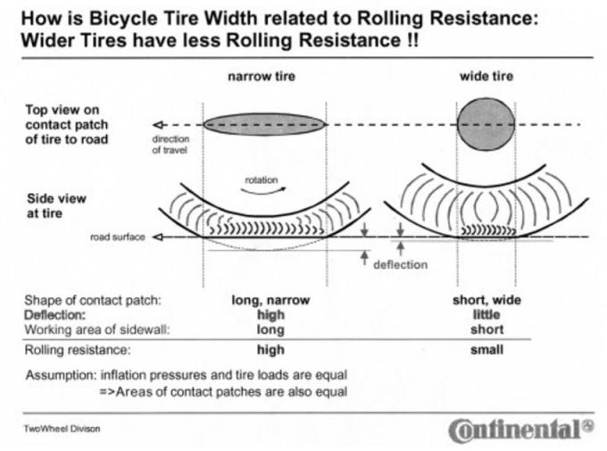
Formula (4), reflecting the described measurement method, directly relates the values of the run-out distance, expressed in the number of revolutions of the drum z, and the residual run-out time T, without causing the need to determine the speed of movement or acceleration (deceleration). This achieves the goal set in the application.
Indeed, each pair of revolutions-time relations of the form (1) - only one such pair is shown in Fig. 2 - gives a system of equations with one unknown B, which is reduced to equation
in which = z 1 / z 2 .
Having found the parameter B from the formula (6), the coefficient c of the resistance to movement is determined according to the dependence
, after which, using the relation (3), the parameter a is found: in order to determine the parameters of no-load losses d 0 and c b , which are calculated respectively by formulas (8) and (7), for a particular case in which the rotating mass coefficient is reduced to
The result is the dependence of the coefficient f of the rolling resistance of the tire on the speed at a given normal load and internal pressure 0 , (11)
k r =c-c b .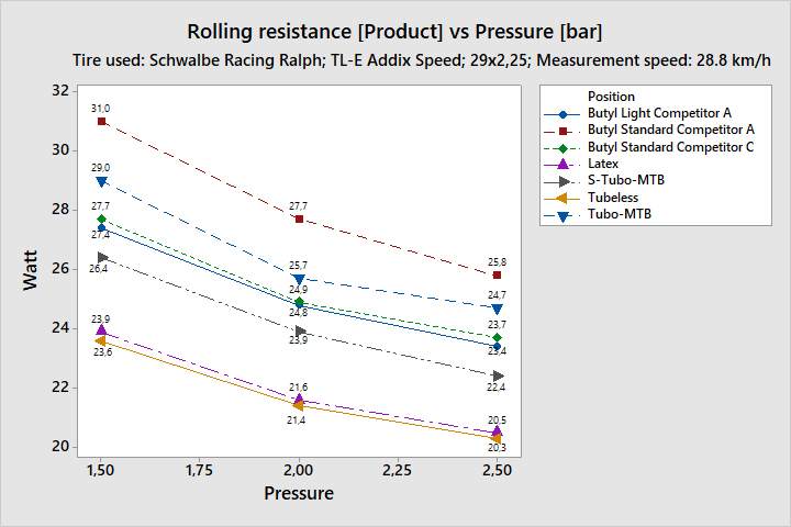 (12)
(12)
In the case of using only one or two marks on the drum, the decrease in the accuracy of measuring the number of revolutions is compensated by grouping the obtained ratios between z and T in pairs in a difference of the form z i -Z j and equating them to each other, which gives
where
(8).
Similarly, dependencies are presented for the parameters of the idling resistance of the stand d 0 and c b , using relation (9) in them to determine the coefficient of rotating masses, after which the dependence of the rolling resistance coefficient on speed of the form (10) is found.
The method can be used to determine the quality parameters of tire products by the rolling resistance parameter in the laboratories of tire and car manufacturers using drum stands available there, thereby eliminating the need to create special stands for measuring tire rolling resistance.
Sources of information
1. VL Biderman, RL Tuslitser et al. Automobile tires (design, calculation, testing, operation). - M.: Goshimizdat, 1963, p. 303-304.
2. ISO 8767:1992 (E). Passenger car tires - Methods of measuring rolling resistance.
3. V.I.Novopolsky. Rolling loss measurement. Proceedings of the Research Institute of the tire industry. Collection 3. - M.: Goshimizdat, 1957, p. 122.
Formula of the invention
on the signals of which time marks are made and connected to the recording device, and the value of rolling resistance is judged by the ratio between the numbers of revolutions of the drum made from some instantaneous value of time to stop, and the values of the time of their completion, moreover, to measure the numbers of revolutions of the drum and the corresponding overrun time use the same sensor signals.