Trying to see how to test a cdi box with a multimeter?
Super, you are in the right place!
In this ToolsGaloreHQ.com blog, we will show you:
Check out the table below before continuing with the rest of the guide on how to test cdi box with a multimeter.
What you need to know about how to test CDI box with a multimeterThe capacitor discharge ignition (CDI) as you know is that black box on your motorcycle that basically functions as the brain of the ignition and motor unit.
This unit is typically found underneath the seat.
It is so common in motorcycles now a days, and has all but replaced the old mechanical trigger mechanisms of the past (before 1980’s).
Before we get into the various steps on how to test your cdi box using a multimeter.
Let's understand a few critical components of the CDI to ensure that your testing is not just theoretical but is backed up by a firm and solid understanding of the underlying electronics involved.
Internal Workings of your CDI
The CDI has the components as shown in the image below
Source: usman032.com
The alternator (exciter) coil is typically powered with an AC voltage ranging anywhere up to 400 Vac.
This passes through a forward biased diode and produces a DC voltage which is inturn fed to the micro-capacitor and the silicon controlled rectifier (SCR).
The SCR is further controlled by a pulse coil which dictates it’s open and close position.
Read More:>> Find the Best Multimeter under $50
When the SCR is closed. This creates a short circuit causing current to flow from the charged capacitor in the direction as shown below.
This charges the ignition coil before releasing the energy to the spark plug, and hence providing energy to the engine.
There are various symptoms that can be derived from a defective cdi. Of which you will be able to use a multimeter to test. They are listed here below.
Misfiring engine
There are many reasons as to why an engine could misfire.
Getting the help of a professional mechanic would usually be your best bet. However a worn out ignition coil found within the cdi is a very common issue with misfiring engines.
Dead Cylinder
This occurs when one or more of the cylinders fails to fire properly.
Often what will happen is that the CDI could have a defective blocking/forward diode, creating fuzzy voltage signals which inturn confuse the spark plug’s firing mechanism.
Backfiring
This tends to happen at higher RPMS above 3000. It can be an issue on the stator, but it has been shown that a bad cdi can contribute to backfiring.
SafetyPlease ensure that whenever you are working with cdi parts or motorcycle mechanics you ensure that you use the typical Personal protective equipment.
The minimum that should be use cut resistant and water proof mechanical gloves, protective and protective eyewear.
I can tell you from experience working with electrical equipment that safety and the dangers that come from not protecting yourself adequately can be very dangerous.
CDI’s are active components that have capacitance inside although this is usually minimal (i.e. micro farads). You should not take your safety lightly.
Step 1 -Remove CDI box from motorbike
The CDI is usually connected with insulated leads and pin connectors. Disconnecting this from the motorcycle should not be too difficult.
Make sure that you do not work on the cdi immediately.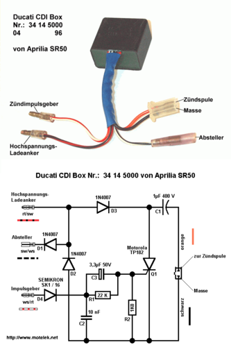 Let it sit for at least 30 minutes to 1 hour to allow the internal capacitance to discharge.
Also during this step, it is important to run a visual inspection of your CDI. Typically damaged CDI’s have some form of mechanical deformation in the form of heat or damaged insulation from the casing.
Read More:>> Testing Purge Valve using a Multimeter
Step 2 – Testing CDI (Cold Test)
Here is the image we used above again as a reminder of the internal circuitry
This method requires us to test the cdi for continuity.
So what you would do is set your multimeter to continuity mode. First take the leads of the multimeter and connect them together.
If you are using a digital multimeter then you should hear a beeping sound.
Measure for continuity between all the ground and the various other points.
If your cdi is working well, you should not hear any sounds. If you do however hear any beeping sound as you are testing, then you cdi is faulty.
All is not lost at this stage, the cdi can still be rectified if you are able to fix the defective component.
Usually on a cdi when you have continuity between ground and any of the other terminal points , it either means that the diode, scr or the capacitor has failed.
Step 3 – Testing CDI (Hot Test)
There is an alternative method to testing the cdi box whilst it is still connected to the stator of the motorbike. Generally cdi boxes have a blue and white wire than comes from the stator to the cdi box itself.
When testing for continuity on the multimeter, it is important to test via the stator end rather than the cdi end.
This is because it is notoriously difficult to get any test lead connection through to a connected cdi box.
The voltage, continuity and resistance is generally the same as on the stator end.
There are a couple of things that you would want to test. Namely:
 Whilst in general the white wire to ground should provide you with a resistance of between 360 to 490 ohms.
This will provide you a genera hot health status check of your cdi box. If the resistance values on your multimeter reading go outside of this range. It is worth checking it with a mechanic.
Read More:>>> Learn more about clamp meters vs multimeters
Final thoughts on how to test CDI box with a multimeterHaving a motorbike that does not fire correctly or produces cracky idling can be a pain to diagnose.
One thing that is often overlooked in checking the cdi for it’s health and functionality with a multimeter.
I hope this guide has provided you with additional insights as to how to test your cdi box with a multimeter.
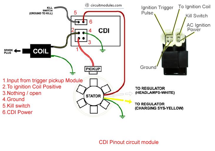
Functions: The CDI box receives a pulse signal from the stator. It then calculates when the engine needs to fire the spark plug. At the appropriate time, the box sends a pulse to the ignition coil, when then fires the spark plug. (For more information on this process, see Anatomy of an ATV – Ignition Coil.
What is a CDI box? The CDI box shown below is a 6-pin box. Functions: The CDI box receives a pulse signal from the stator. It then calculates when the engine needs to fire the spark plug. At the appropriate time, the box sends a pulse to the ignition coil, when then fires the spark plug. (For more information on this process, see Anatomy of an ATV – Ignition Coil.
How much are ATV CDI boxes? MotoSport.com offers 9 ATV CDI Boxes. A leader in our industry, we know you’ll be satisfied with your CDI Boxes when you buy from us. We want to make your next ride, your best ride. Our ATV CDI Boxes ship for free with orders over $79. If you need some assistance, we can help.
What does the CDI do in a scooter? The CDI in your scooter is linked to the ignition. Therefore, if it is in good condition then you will have fewer or no issues with your ignition. It plays the role of storing electrical charge and increasing the spark power on the spark plug.
Can a bad CDI cause sparks? Sometimes, a bad CDI does not cause sparks at all. Again, when a CDI box is about to go bad, it can lead to misfires, issues with starting, rough running or even stall the motor.
Table of Contents
You can temporarily bypass a CDI box for troubleshooting purposes. The box amplifies the small signal generated from the spinning magnet located in front of the pickup coil in the stator, just before top dead center (TDC), when your fuel-air mixture is ignited.
The CDI is not easy to diagnose because the observable symptoms of a faulty CDI box can lead to different directions. Sometimes, a bad CDI does not cause sparks at all. Again, when a CDI box is about to go bad, it can lead to misfires, issues with starting, rough running or even stall the motor.
CDI Box. Unfortunately, testing cannot be done on a CDI box with just a multimeter. The only way for a home mechanic to test for the CDI is to swap it with a CDI that is known to work. It’s for this reason that the CDI should be the last thing that you check.
First measure the resistance between the primary wire that comes from the CDI box and the ground or ground wire. The resistance should measure around . 5 to 1.5 Ohms. If that checks out, you can then measure the resistance between the secondary wire (plug wire), w hich should measure in the thousands.
Functions: The CDI box receives a pulse signal from the stator. It then calculates when the engine needs to fire the spark plug. At the appropriate time, the box sends a pulse to the ignition coil, when then fires the spark plug. (For more information on this process, see Anatomy of an ATV – Ignition Coil.
First measure the resistance between the primary wire that comes from the CDI box and the ground or ground wire. The resistance should measure around . 5 to 1.5 Ohms. If that checks out, you can then measure the resistance between the secondary wire (plug wire), w hich should measure in the thousands.
Yes, a poor cdi can cause a weak spark.
Troubleshooting CDI systems Symptoms could include misfiring, dead cylinders, backfiring, bizarre tach behavior, and countless other things related to how your engine’s running. The problem may get worse as the bike warms up. It might not even hold low revs at all.
A capacitor discharge ignition box (CDI) box is used in motorcycles, turbine-powered aircraft, outboard motors, and some cars. You can temporarily bypass a CDI box for troubleshooting purposes. Thus, it’s unable to store enough voltage to keep the engine running.
CDI Box. Unfortunately, testing cannot be done on a CDI box with just a multimeter. The only way for a home mechanic to test for the CDI is to swap it with a CDI that is known to work. It’s for this reason that the CDI should be the last thing that you check.
So you’ve got a spark problem on your CDI-equipped motorcycle.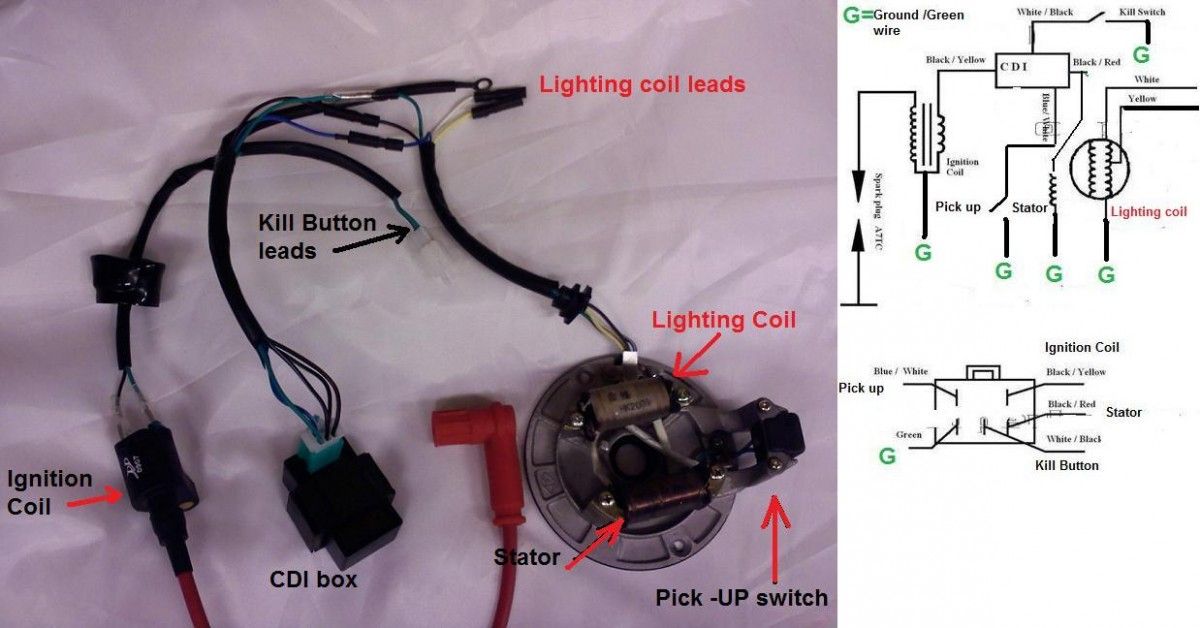 Symptoms could include misfiring, dead cylinders, backfiring, bizarre tach behavior, and countless other things related to how your engine’s running. The problem may get worse as the bike warms up. It might not even hold low revs at all.
Because ignition characteristics (particularly timing) vary widely across vehicle models, there’s no one CDI box that can cover them all. The CDI must be matched to the engine that’s being worked on. The CDI boxes in these systems are not interchangeable.
A capacitor discharge ignition box (CDI) box is used in motorcycles, turbine-powered aircraft, outboard motors, and some cars. You can temporarily bypass a CDI box for troubleshooting purposes. Thus, it’s unable to store enough voltage to keep the engine running.
Symptoms could include misfiring, dead cylinders, backfiring, bizarre tach behavior, and countless other things related to how your engine’s running. The problem may get worse as the bike warms up. It might not even hold low revs at all.
Symptoms could include misfiring, dead cylinders, backfiring, bizarre tach behavior, and countless other things related to how your engine’s running. The problem may get worse as the bike warms up. It might not even hold low revs at all.
CDI Box. Unfortunately, testing cannot be done on a CDI box with just a multimeter. The only way for a home mechanic to test for the CDI is to swap it with a CDI that is known to work. It’s for this reason that the CDI should be the last thing that you check.
Friends, do not flatter yourself too much. The Internet, in particular, this site is intended only to help you in solving a particular problem. And the rest will depend only on you, or rather, only on your desire and nothing more.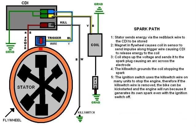
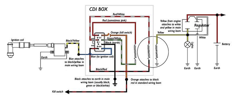
To put it simply, the switch is a certain module (according to Feng Shui - DC CDI or AC CDI module) in which electrical energy is accumulated, which at the right time is supplied in the form of a pulse to the ignition coil, where it is multiplied many times in the form of electrical sparks jump between the electrodes of the spark plug.
The scooter commutator looks something like this
Depending on the type of commutators, the energy needed to form spawn can be stored in the commutator in two ways:
Offal
The switch power coils on the generator look something like this. Some alternators have two, some have only one
In order for the spark to pass at the right moment, a magnetic induction sensor was introduced into the design of the generator and the commutator like it (in the collective farm - “hall sensor”). The magnetic induction sensor is essentially a conventional alternator, only in miniature.
On the outer side of the generator rotor there is a small protrusion, when it passes near the sensor - a small alternating pulse is formed in the sensor windings, which enters the thyristor of the switch - the thyristor opens and the energy stored in the capacitor is supplied to the ignition coil
Sensor
For work we need:
In order not to waste time - the test should begin with checking the electrical impulse that accumulates in the switch and enters the ignition coil at the right time.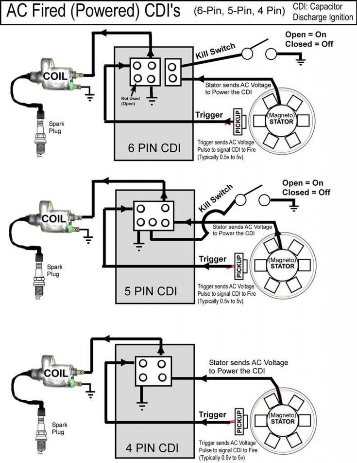
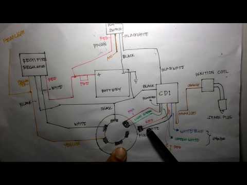
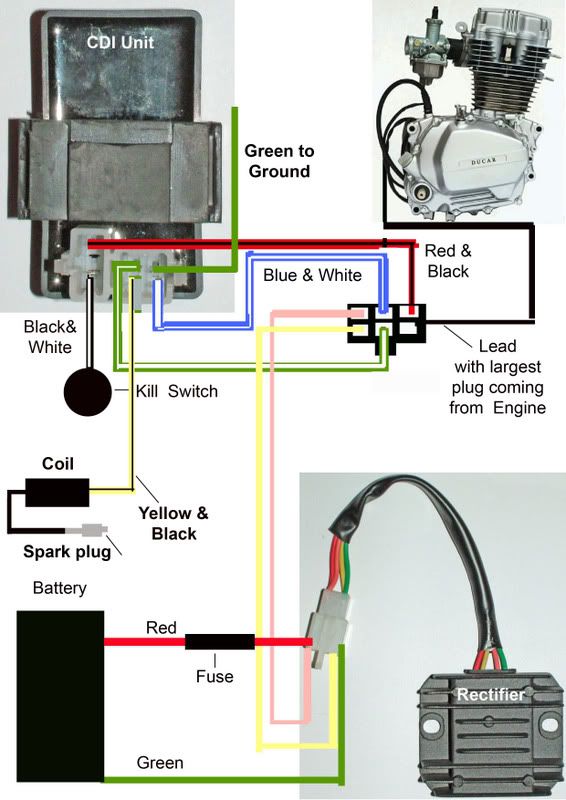
We take a control light and connect it with one end to the green ground wire, the other to the black and yellow wire of the ignition coil. We turn the engine with a starter.
If the switch and the modules that ensure its operation are in good condition, the 3W light bulb in the engine cranking mode with the starter should burn to the floor of the glow
We take the tester, put it into the "dialing" mode (diode icon or sound signal icon), look for green wires on the switch - this is something other than a mass (according to Feng Shui - a negative wire), with any probe of the tester we touch the metal part of the engine , with another probe we poke into the green wires:
Depending on what the tester shows you, fix the problem or continue checking:
An example of a good mass: the tester beeps in the "dialing" mode, solid zeros on the display
In order for a spark to jump between the electrodes of the candle, the switch capacitor must be charged from something. And it is charged either from a battery or from a generator. Means what? Correctly! Check if power is being supplied to the switch.
Before starting to measure power, we determine what type of switch is on your scooter. If visually, then DC CDI type switches are twice as large as AC CDI. But this is not an exact criterion. The most accurate criterion - see the output of the high-voltage generator coil:
The output of the high-voltage coil of the generator is located in the same place as the output of the generator itself: we are looking for where the wires coming from the generator are connected to the on-board network of the scooter and if one of the two wires with round terminals is not connected, then the coil is not involved
measurement of direct current in the range of 20 V.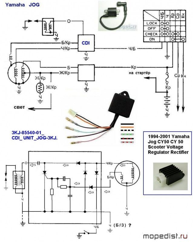 We are looking for a power wire on the switch. Usually this is a black or gray wire, we touch the ground with one probe, the power wires with the other:
The power supply of this switch is in order
We switch the tester to the mode of measuring alternating current in the range of 200V. We touch the ground with one probe, the power wires with the second and turn the engine with the starter:
 The supply winding of the generator in the mode of cranking the engine with a starter must produce at least 60V, and at medium engine speeds - about 160V
The magnetic induction sensor is a key element of the ignition system. And if there is any suspicion of a malfunction in the ignition system, it should also be checked.
Switch the tester to AC measurement mode on the 2V range. With one probe we touch the mass, with the second probe we touch the white-blue or red-yellow wire coming from the sensor and turn the engine with a starter.
There is an impulse
 And in order to accurately understand that the switch is faulty, we need to check all the modules.
 In conclusion, I would like to warn you against the temptation to take a known-good switch from someone and plug it in instead of your own. Yes, with this express method, a faulty switch will be determined immediately. If it really was faulty, then a spark will immediately appear with a known good one.
But how can we be 100% sure that the scooter's wiring is in perfect order and no one has managed to put their smart personality into it before you? your own way and then the working switch will receive a “full ass”. And then wake up to buy two switches - one to the one you asked for, the second to yourself. And do you need it?
I don't know what it is connected with, but most owners of scooters and motorcycles equipped with a CDI ignition system, if there is a problem with a spark on a candle, they immediately sin on the ignition coil.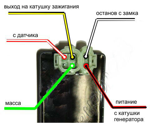 To all my reasoned arguments in favor of the fact that, in addition to the coil in the electrics of the scooter, there are still a bunch of devices that provide sparking between the electrodes of the spark plug: a generator, an induction generator sensor, a switch, wires in the end - they make glass eyes and repeat their signature phrase as one : "Can't you call her?" You can't, my dears, you can't!
No, of course I can make a smart person and, for solidity, poke a coil in front of you with a tester, as collective farm gurus do. But I won't do that today. For one simple reason: you can “ring out”, measure the resistance of the coil windings, but what will it give us? .. Well, the tester will show us the treasured numbers on the display, so what? And if there is an internal turn-to-turn short circuit in the coil windings, a factory defect, or the winding of one of the coils burned out. Do you think with the help of a tester you can determine all these malfunctions? I assure you not.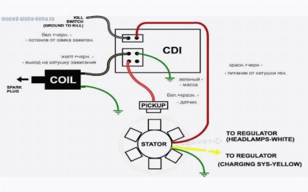
Therefore, since it comes to that and you are inclined to believe that the absence of a spark can still somehow be connected with the ignition coil - we will go from the opposite. Namely: today we will not learn how to check the coil itself, since it is useless and does not give anything, but we will check the electrical parameters of the devices that ensure the operation of the ignition coil. This approach to diagnosing such devices is more effective than the usual “ringing” of the windings for a break or resistance measurement.
The CDI ignition coil is a classic two winding high voltage transformer. The work of which is based on the effect of magnetic inductance.
Inside the ignition coil there is a cylindrical or rectangular core over which a large amount of the thinnest copper wire is wound in a strictly defined order, which is the secondary winding. On top of the secondary winding, a thicker copper wire is wound through the insulation layer, which is the primary winding.
Both windings are connected at their ends to each other and have one common terminal on the body in the form of a ground terminal (green). The second ends of each of the windings have separate outlets on the body in the form of a power terminal and a central contact of a high-voltage wire.
For more clarity, let's break the case and see what's inside.
During engine operation, the alternating current generated by the high-voltage winding of the generator is supplied to the switch in which it is accumulated in a special capacitive storage (capacitor) - this current accumulation principle applies only to AC CDI switches. There are even less common DC CDI switches that use direct current from the battery for storage.
Hence the name of the CDI system, from Capacitor Discharge Ignition - loosely translated, it sounds something like this: “ignition from a capacitor discharge”
the moment of sparking, a special element in the switch (thyristor), which acts as an electronic key.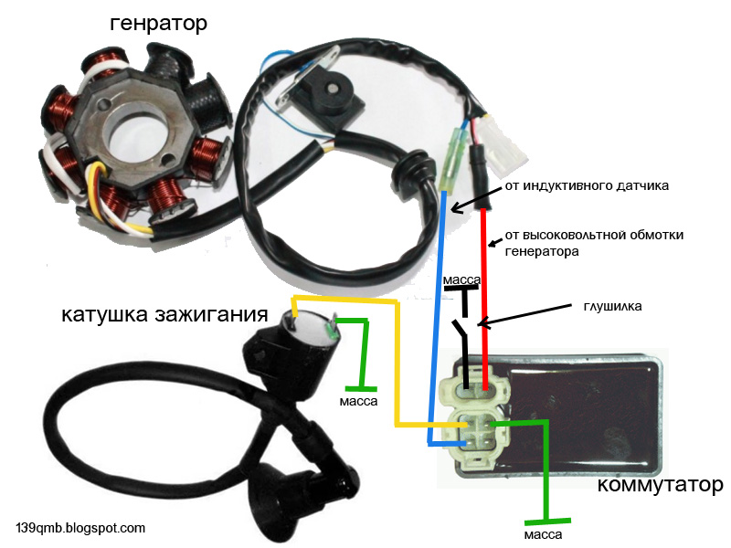 Further, the following happens: the thyristor, under the action of an alternating pulse from the induction sensor of the generator, opens and the current accumulated in the capacitor in the form of a pulse shoots through it to the primary winding of the ignition coil.
When a pulse passes through the primary winding, magnetic induction occurs, under the influence of which an electric current is induced in the secondary winding, many times higher than the current supplied to the primary winding in voltage. In fact, in the ignition coil, there is the most transformation of current from a lower (incoming) to a higher (outgoing) current.
The current formed in the secondary winding, through a high-voltage circuit, enters the spark plug and, due to its high voltage, about 18,000 - 20,000V, easily overcomes the air resistance between the electrodes and forms a spark.
Malfunctions as such in the CDI ignition coil are very, very rare, contrary to popular belief.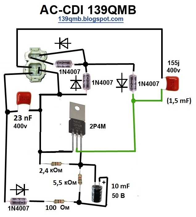 And all of them are mainly associated with damage to the case, burning of the windings, or an internal break, short circuit of the wires.
In all my hard practice, I have only once come across a really faulty coil. And this despite the fact that the owner of the scooter himself ruined it: he forgot to connect the ground to the engine and turned on the starter button ... A very high starting current went straight through the coil to the starter ... And where was he supposed to go? .. There was no mass on the engine. Naturally, the coil could not stand such mockery: it heated up and burst.
For work, we need an ordinary tester with a sound “ringing” function, a 3W control lamp, a piece of thin wire or a carnation, a piece of insulated wire, a screwdriver and, of course, a desire ...
Herself verification is not particularly difficult even for beginners. And it will be connected with measuring the supply voltage supplied to the coil, checking the mass, which must necessarily fit the engine, switch and coil, and checking the integrity of the wires supplying current to the consumers of the ignition system.
Another point: the technique that will be described here can be safely applied not only to a scooter, but also to any other type of vehicle equipped with a CDI ignition system, be it a motorcycle, an ATV, a scooter or even a walk-behind tractor - it doesn’t matter.
Whether the power supply (impulse) goes from the switch to the coil or not depends on whether the coil will produce a spark to the candle or not. Power is power, without it, no electrical consumer can work. Therefore, any check should begin with a power check - is it there or not? And only then, depending on the result, finish the check or move on.
We release access to the coil and without removing the terminals from it - we connect the control light to the power wires: green and black and yellow and turn the engine with a starter. In the mode of cranking the engine with a starter, the control light should burn to the floor of the glow.
The light on the coil is on - the switch is 100% working.
If your light is off, check the switch and if it is working and there is no voltage at the coil terminals, look for the cause in the wires supplying power to the coil.
The voltage on the switch is checked in the same way as on the coil: touch the green and black-and-yellow wires, turn the engine with a starter and look at the light bulb.
The light on the switch is on, it means it is 100% working.
Another common cause of coil failure when there is power at the coil terminals is poor or no ground. The mass on the coil is checked simply: we put the tester into the sound “ringing” mode, touch any metal part of the engine with one probe, and the green ground terminal with the second.
This spool has good ground.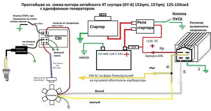
Malfunctions in the high voltage circuit often leading to a complete or partial (interruption) failure of the ignition system are mainly associated with damage, contamination or breakdown of the spark plug cap housing or breakdown of the insulation of the high voltage wire.
As I said: the current generated by the secondary winding of the ignition coil is very high and it is not uncommon for the current supplied to the spark plug to break its way through cracks in the cap body or a layer of dirt, dust, cracks in the insulation of the high-voltage wire. Which leads to a complete failure of the ignition system. These malfunctions occur very, very often and in most cases lead to a complete or partial (interruption) failure of the ignition system.
In order to check the high-voltage circuit, do the following: We twist the cap from the high-voltage wire; insert a thin nail or piece of wire into it; we bring the nail to the metal case of the engine at a distance of 2-3mm ( This is important! The distance between the end of the wire and the motor housing should be 2-3mm, otherwise screw the switch ) and turn the motor.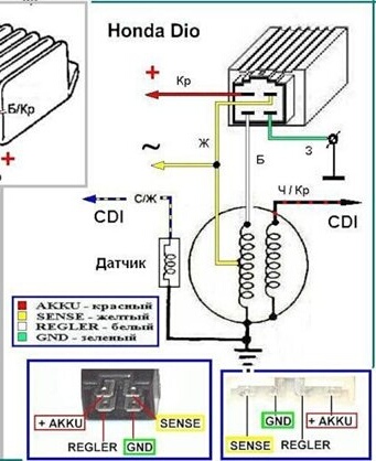
We check the high-voltage wire in a similar way: We unscrew it from the coil and screw in any other piece of insulated instead of it (The wire must be insulated! Otherwise, it will slap so that it won’t seem enough!) wires, bring it to the engine housing at a distance of 2-3mm and turn the engine.
That's actually the whole technique. I've been testing coils this way for a few years now. And for a complete check with almost one hundred percent accuracy, it takes me only a few minutes. Of course, this technique may seem complicated to many of you, but in fact it is not quite so. The main thing is to understand the principle, the rest will follow by itself.