Before attempting to remove and mount tires on rims, there are important safety precautions to know. Serious personal injury can result if proper caution is not observed. Tires can explode if attention to certain details go overlooked.
* Always be sure the tire is of the specified size and construction for the rating of the wheel.
* Check that the wheel diameter matches the diameter molded on the tire sidewall.
* Never exceed 40 PSI when seating tire beads.
* Never inflate tire above tire manufacturer’s recommended pressure after beads are seated. Tire problems such as leaks and vibrations can sometimes be traced to improperly mounted tires.
Operators Protective Gear and Equipment
Personal protective equipment helps make tire changing safer. However, equipment does not take the place of safe operating practices. Always wear durable work clothing during tire service activity. Shop aprons or shop coats may also be worn, however loose fitting clothing should be avoided. Tight fitting leather/mechanics gloves are recommended to protect operator’s hands when handling worn tires and wheels. Sturdy leather work shoes with steel toes and oil resistant soles should be used by tire service personnel to help prevent injury in typical shop activities. Eye protection is essential during tire service activity. Safety glasses with side shields, goggles, or face shields are acceptable. Back belts provide support during lifting activities and are also helpful in providing operator protection. Consideration should also be given to the use of hearing protection if tire service activity is performed in an enclosed area, or if noise levels are high.
Tire Changer Equipment Operator Safety - Owner’s Responsibility
Whether you're using a tire changer for cars and trucks or an ATV and motorcycle tire changer, it comes with very detailed and easy to understand instruction manuals. Read and understand your tire changer’s owners/operators manual completely before using the machine. These manuals assume that the operator has used a wheel clamp style tire changer previously, or has operators that have operated a wheel clamp style tire changer. If this is your first tire changer purchase/experience and you have not operated a wheel clamp style tire changer, it is strongly recommended to have a person/trainer who is familiar with this style of tire changer train you in the operation. Some tire changers may appear very similar to many other tire changers on the market but may operate differently. The distributor that sold the machine will be glad to give you a training session at their location or guide you to someone who can provide a service call to your location for training (a service charge would apply). The distributor also offers telephone technical support and troubleshooting suggestions as needed. This does not take away from the responsibility you have to read and understand the complete manual.
 This responsibility is no different than when you purchase an automobile. The automobile dealer assumes you know how to operate and drive a motor vehicle. Safe operation is your responsibility and the dealer assumes you know how. Seek training as needed.
Deflating the Tire
Before removing the tire from the wheel, use a valve core removal tool to remove the tire valve core and deflate the tire completely. If the tire is to be patched and reinstalled without balancing, be sure to mark the locations of the valve stem and any wheel weights with a marking crayon. If another tire is to be installed on the wheel, remove any wheel weights from the wheel first.
Never attempt to break down the beads of an inflated or partially inflated tire.
4-Way Valve Core Tool
Tire Changers
Early tire changers had a center post mounting system that required the tire and wheel assembly to be lifted onto a threaded center post. This style of tire changer was the standard of the industry until the 1990’s.
Center Post Tire Changer
The Wheel Clamp style tire changer was originally developed in Europe and has become the predominant tire changer in North America. The popularity of the wheel clamp tire changer is a result of meeting the needs associated with changing tires on high performance and specialty aftermarket wheels. Today it is more common to find specialty aluminum, painted and coated finish wheels that require the delicate handling provided by the wheel clamp style tire changers. As wheel diameters have become larger and tires more low profile, the wheel clamp tire changer has become a must for every tire shop.
Weaver W-898XS Wheel Clamp Style Tire Changer
Special pneumatic assist arms have been added to aid the tire changer in changing difficult stiff sidewall and low profile tires. These assist arms are air hydraulic and have the power needed to push the tire beads into the wheel’s drop center to allow the tire to be mounted or demounted.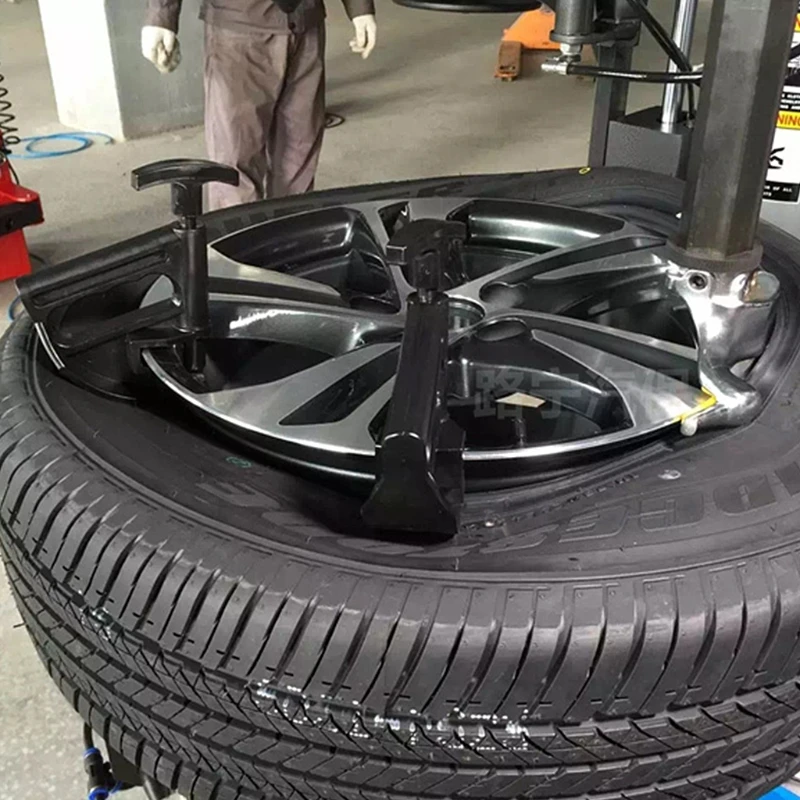
Weaver W-898XS Tire Changer with W-PL240 Assist Arm
Breaking the Beads
To remove the tire from the wheel, both of the tire beads need to be unseated from the bead seats on the wheel. This is called “breaking the beads”. The bead breaker is located on the right side of the tire changer and is operated by foot pedal. The tire is rolled in between the bead breaker arm and the padded side of the machine. The bead breaker blade is placed on the tire bead and slightly off of the wheel lip as to not contact the wheel rim. The pedal is activated to break the bead away from the wheel. Keep hands and legs away from moving parts. The wheel is turned around to break the bead on the other side of the tire. The tire may be moved to break other areas on the tire until the beads are completely detached from the wheel.
Plastic protectors are used on the bead breaker blade to prevent scratching the wheel as the blade slides by the wheel.
Bead Unseated from Rim on Weaver W-M807 Motorcycle Tire Changer
Care is taken to locate the valve stem to the opposite side of the bead breaker to avoid damage to tire valve stem that may have a tire pressure monitor system (TPMS) installed.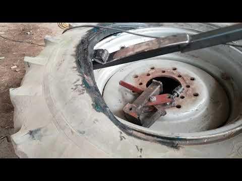
TPMS Tire Pressure Monitor System in Valve Stem
Safety First - Do Not attempt to unseat the beads of an inflated tire. Do Not strike the tire or wheel with a hammer. Something is wrong if you need a hammer. When removing a tire from a rim, never let go of the tire iron. It can flip up and hit you.
Clamping the Wheel on the Turntable
Before placing the wheel with the detached tire on the clamping table, lubricate both beads with rubber lube (Rubber lubricant is covered later). There are two methods for clamping a wheel on the turntable.
Inside Clamping will clamp the wheel from the inside of the wheel. The clamps are positioned close together and the wheel is then placed over the clamps. The foot pedal is activated to clamp the wheel from the inside out. The clamps will expand outward and securely lock the wheel in a centered position.
Outside Clamping will clamp the wheel from the outside flange of the wheel’s rim. The clamps are first expanded to the outward position and will clamp from the outside in.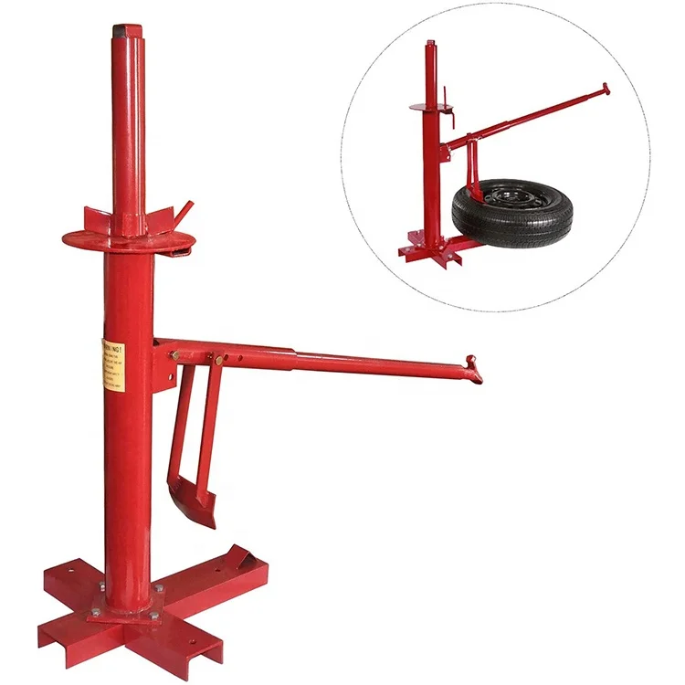 The wheel is placed over the clamps and the tire will rest on top of the clamps. While viewing the clamp position from underneath wheel, close the clamps inward onto the wheel by depressing the foot pedal. The wheel may need to be pushed downward into the open jaws of the clamps. Tire changers equipped with an assist arm can be used to push the wheel down into position while activating the clamps. The clamps will securely lock the wheel in a centered position.
Wheel Clamps Positioned for Inside Clamping
Plastic protectors are used on the clamping jaws to protect the wheel’s finish.
Note: The clamping range of a tire changer may sometimes be confused with the wheel diameter because the range is shown in actual inches. Wheel diameters may require more or less distance to be clamped because of the varied thickness of many wheel flanges. Not all 20” wheels are made the same.
Rim Diameter plus Flange Height = Outside Clamp Range Needed
Demounting - Removing the Tire from the Wheel
Once the wheel has been clamped onto the turntable, the hex shaft may be lowered to bring the mount/demount head (aka - Duckhead) to the rim’s edge.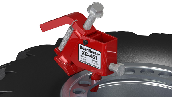 The duckhead will rest on the outside of the flange and on the top of the wheel. The hex bar is then locked and will automatically be retracted vertically away from the wheel surface about 1/16th” or 2 mm to prevent touching the wheel while demounting/mounting. Swing arm style changers also have a large screw to move the mount head horizontally about 1/16th” or 2 mm away from the wheel flange. Most modern steel duckheads have plastic inserts to protect the rim should the head come in contact with the wheel during the mounting process. Complete plastic duckheads are also available.
Duckhead in Correct Position for Demounting/Mounting the Tire.
Once the duckhead is in place, the upper bead can be pulled over the edge of the rim and duckhead with the tire iron only after the bead on the bottom opposite side of the tire is forced into the wheel’s drop center.
Tire Tool is inserted over duckhead and under tire bead.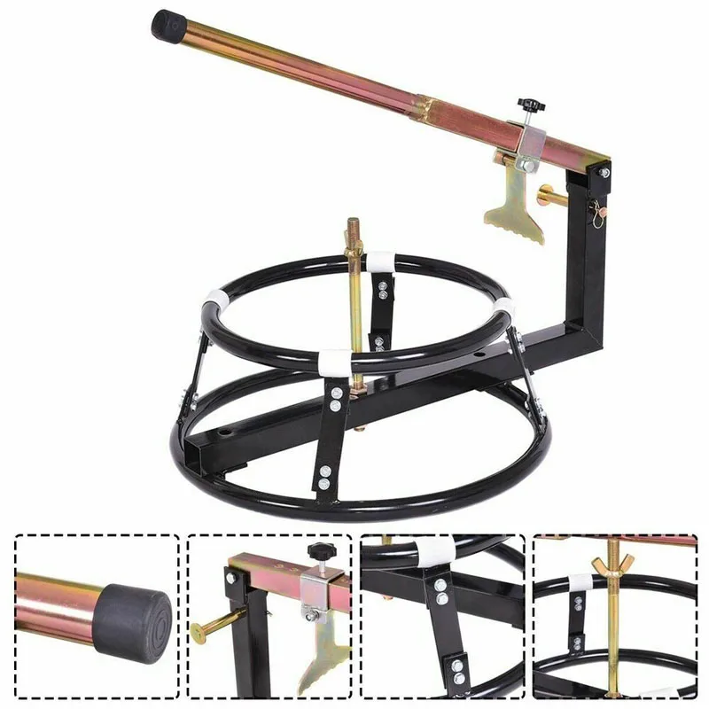
Tire Tool is used to lift bead over the demount side of duckhead with opposite side bead in drop center.
Be careful not to tear the bead or the tire will be ruined. If the bead gets stuck or binds be sure to apply enough rubber lube to the bead. Also double-check the that the lower bead is in the drop center of the wheel 180 degrees from the duckhead.
Both Beads are in the Drop Center of the Wheel while the Bead is pulled over the edge on the opposite side of the Rim.
First the upper bead is pulled over the outside of the rim, followed by the lower bead. Never try to remove both beads at the same time. When the upper bead is over the duckhead, the foot pedal is activated to rotate the turntable clockwise. The tire iron is held in place and will ride the tire clockwise until enough slack in the tire allows the tool to be removed. The demount head will guide the upper bead up and over the edge of the wheel. Push down on the tire across from the demount head while the turntable is in rotation to utilize the drop center area of the wheel.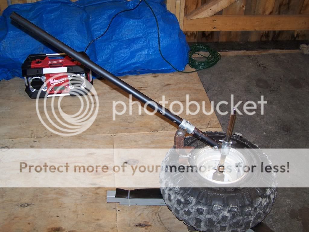 This reduces the tensional force on the top bead or first bead during demount. The process is repeated for the lower bead and the tire is removed from the wheel. By moving the hex bar and demount head away from the wheel the tire can be taken away from the wheel and tire changer.
A tire that is in a bind can be unjammed by lifting the pedal up to reverse the turntable counter clockwise until the jam is cleared. At times during the mounting and demounting procedure, the bead lifting tool may encounter resistance or come under load. Keep one hand firmly on the tool to avoid possible tool disconnect. Use the reversing feature to back out of jams. In the process of demounting tire, you should keep your hands and the other parts of your body as well as clothing from the movable parts to prevent injury.
Inspecting the Tire and Wheel
After the tire has been removed from the wheel, inspect the inside for cuts, carcass damage, penetrating objects, loose cords, dirt and liquid. Inspect the condition of each bead by pulling out on it in several places around its circumference. If the bead has any sharp bends in the bead DO NOT mount the tire. The bead wire could be broken. It is not worth taking a chance with someone’s safety.
Note - Never mount a tire or wheel that is damaged. This could result in injury or death to the occupants of the vehicle. Liability could be held by the shop and/or technician in such a case.
Inspect the condition of the wheel for sharp edges, dents, cracks and other damage. Small dents in the wheel flange can sometimes be straightened. Larger dents need to be checked for radial and lateral runout with a dial indicator before it can be determined useable. Excessive runout can cause the car to shake at higher speeds. Rust can damage the bead seat on a wheel. If rust is on the surface only, it can be removed with a wire brush. If the bead seat is not smooth, the tire will have a slow leak and the wheel will need to be replaced.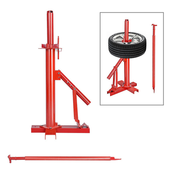
Valve Stem Service
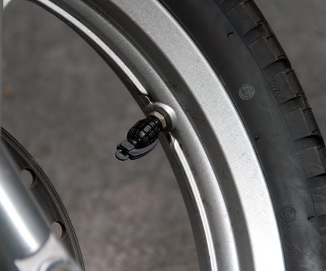
Ordinary rubber valve stems are customarily replaced during tire service or when new tires are installed. The valve stem can also be replaced without removing the tire from the wheel. This is done when an old valve stem becomes aged and cracked or starts to leak. Leaks can be found by prying the stem to the side and observing any air leakage.
Old Valve Stem replaced with a New Valve Stem
To remove a valve stem, cut it off with a knife or force it through the hole in the wheel using a valve stem installing tool. Remember to install the valve stem before installing the tire. To install the new valve stem, thread it into the installation tool, lubricate it with rubber lube and pull it into the hole. Be sure it is completely in the hole and is properly seated.
A new valve stem comes with a new valve core inside. Remove the valve core before attempting to inflate the tire.
TPMS Tire Mounting and Demounting
Be careful not to damage a direct-type TPMS when dismounting and mounting tires on rims.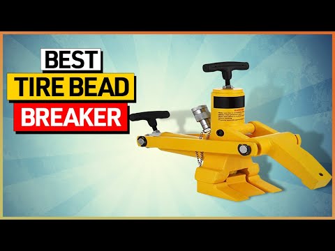 Do not force the tire over the sensor or it can be broken or the tire bead can be damaged. If the sensor is part of the valve stem, be sure that the bead breaker is positioned across the wheel from the valve stem. If the wheel has a banded sensor, it will be mounted in the drop center, 180 degrees from the valve stem. Position the bead breaker accordingly. cars with run-flat tires have used direct tire pressure monitors for many years. These tires have extra stiff sidewalls and can be very difficult to work with if the tire changer does not have a power assist arm.
Directional Tires
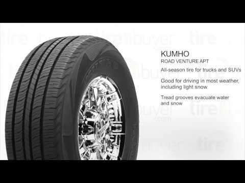
Some tires are designed to only run in one direction. These will have an arrow indicating the direction of rotation. Check the tire sidewall to see if there are direction arrows.
Directional Tire
Be certain that the correct side of the tire is facing out. Some tires have whitewalls or special lettering. All tires have a serial number, which is located on the back side of the tire.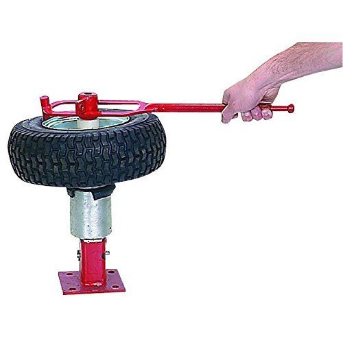
Tire Serial Number
Rubber Lubricant
Radial tire sidewalls are flexible and their tire beads are designed with a close tolerance for a tight fit to the rim. During inflation, the beads are not easily forced into position. If the beads are not seated properly, the tire can have an out-of-round condition when inflated that will make it difficult to balance. Lubricate both tire beads with an appropriate rubber lubricant. Good quality rubber lube is slippery and fast drying. Also lube the bead seats on the rim with rubber lube.
Using rubber lubes provides the following:
1) Reduces friction between the tire beads and the edge o the rim during mounting/demounting.
2) It helps to seal around the bead during initial inflation of the tire.
3) Friction between the bead seats and the tire bead will be reduced when inflating the tire. This is important so that the beads will be all of the way seated and the tire tread will not be distorted.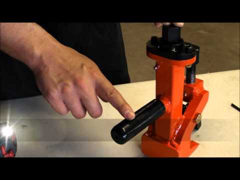 Remember - safety glasses should always be worn when inflating a tire.
Observe the following cautions regarding rubber lubricants:
1) Do not use petroleum products, which will damage the rubber in the tire.
2) Rubber lube should not be diluted with water, which can rust a steel wheel.
3) Do not use silicone lubricants or liquid soaps, which will allow the tire to spin on the rim.
How to Put a Tire on a Wheel
With the wheel clamped on the tire changer turntable, place the lubricated tire on the wheel and bring the hex bar with mounting head into place. Make sure the mounting head is located the proper distance (2mm) off of the wheel edge to prevent touching the rim. Place the lower bead of the tire on top of the back side (ducktail) of the mounting head at an angle that puts the tire bead between the duckhead and ducktail with the front of tire below the duckhead. As the turntable is activated force the bead into the drop center of the wheel as it rotates. This is important! If one side of the bead is not in the drop center, the diagonal mounting distance will be excessive and the other side will not be able to be stretched over the flange. Be careful not to damage a tire pressure monitor during bead installation. When the first bead is totally installed and positioned in the drop center of the wheel, install the top bead using the same procedure as the lower bead.
The bead must be all the way past the edge of the narrow bead ledge or the diagonal mounting distance will not be sufficient to allow the bead to pass over the edge of the wheel.
Mounting Top Bead with opposite side in drop center below narrow bead ledge.
Notice bead at mounting head is below duckhead yet on top of ducktail.
Some tires have a colored dot on their sidewall to indicate the high or low side of the tire runout. Placing this dot in relation to the valve stem will depend on the certain manufacturer’s recommendation as all manufacturers do not use the same location to the valve stem.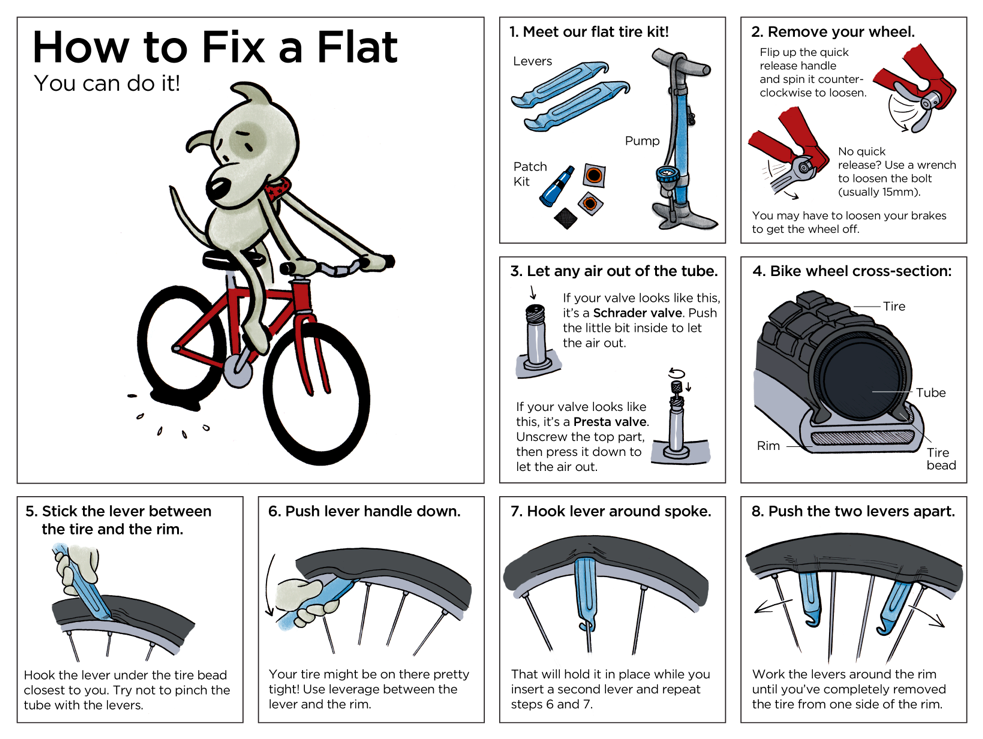
Inflating the Tire - CAUTION!!! Inflating the tire can be the most dangerous part in the tire demounting/mounting process.
It is important to follow the precautions and guidelines noted below: Check for proper inflation gauge operation. Accurate pressure readings are important to safe tire inflation. If the rim has been clamped from the outside for tire mounting, release the clamps, lift the tire, and move the clamps to the center of the table top.
THE RIM MUST BE UNCLAMPED WHEN INFLATING BUT ONLY AFTER BEADS HAVE BEEN SEATED.
If the wheel/tire has a diameter larger than 14 inches and is difficult to bead seal, the clamps should be moved to the center of the table top for the bead seal operation. Tire failure under pressure is hazardous. The tire changer is not intended to be a safety device to contain exploding tires, tubes, wheels, or bead sealing equipment. Inspect tire and wheel carefully for matched size, wear, or defects before mounting.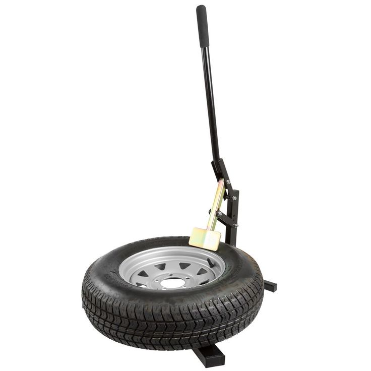 Always use approved tire bead lubricant during mounting and inflation.
The inflation pedal, is typically located at the rear of the left side of the machine and controls the flow of air through the inflation hose.
NOTE: The clip-on chuck on the end of the hose should always be an open style with all parts in proper working order.
ATTENTION! WHEN OPERATING THE BEAD BLAST SEATER IT IS MANDATORY TO WEAR SAFETY GLASSES TO PROTECT EYES.
The Standard Inflation pedal operates in 3 positions as described below
(Check your specific machine’s manual as some may vary).
Position 1 (All the way up at rest) - Tire Pressure –With the inflation hose attached to the tire valve and the pedal in this position, the air gauge will register the air pressure in the tire. Whenever your foot is removed from the pedal, it will return to this position.
Position 2 (Pushed down to the mid level) - Tire Inflation – This is the first activated position. With the inflation hose attached to the tire valve and the pedal in this position, line pressure is allowed to flow through the valve and into the tire for inflation. Tire pressure is not indicated on the gauge in this position. The pedal must be released to read pressure.
Position 3 (Pushed down all the way to lowest level) - Bead Sealing – This is the second and last activated position. With the inflation hose attached to the tire valve and the pedal in this position, line pressure is allowed to flow through the valve and to the inflate bead seal jets on the table top for bead sealing.
Use Position 3 for bead sealing only. Do not use this position without a tire and wheel positioned on the table top. Dirt and debris could be blown into the air with enough force to injure the operator or bystanders. Do not use this position to inflate a tire.
When the inflation pedal is held in position 2, the pressure should be checked every few seconds to prevent over inflation. This cycling helps to prevent over inflation of the tire. Tires can still be over inflated and explode with the use of this technique and if all of the instructions in this guide are not followed completely. It is the operator's responsibility to follow all instructions and to control inflation pressure as specified in these instructions. Tires requiring inflation beyond 40 PSI should be inflated in a safety cage with a clip-on style air chuck. Never exceed recommended pressure after seating beads. Always keep hands and entire body back from inflating tire.
Tire Inflation Safety Cage
Tire inflation is performed in three steps: Bead Seal, Bead Seat, and Inflation.
Bead Sealing
1. Position valve stem in front of operator and connect the inflation hose. Hold tire up against upper edge of the wheel. Be sure tire’s top bead is over the bottom of the valve stem.
2. Depress inflation pedal to position 2 and hold about 1 second to begin air flow through tire valve, then depress pedal to position 3 and hold briefly – less than 1 full second. The blast of air from the jets will expand tire and seal the beads.
3. Release the inflation pedal and allow it to return to position 1. Verify that both beads are completely sealed to the wheel. Repeat these steps if beads have not sealed. It may be necessary to wait a few seconds for the air storage tank to recover before attempting again.
Note: If tire and wheel are properly lubricated and operator cannot achieve bead seal after 3 or 4 attempts, the valve core may be removed from the valve stem to allow more air flow into the tire to assist with bead seal. After bead seal is achieved, remove the chuck and reinstall the valve core.
Bead Seating Operator should keep hands, arms, and entire body away from the tire during the remaining bead seat and inflation procedures. Do not stand over tire, as personal injury could result. Do not leave tools on the tire sidewall when inflating tire. NEVER increase air pressure to exceed 40 PSI when attempting Bead Seat. If operator is unable to obtain Bead Seat, something is wrong. Deflate tire completely, inspect tire and wheel, and correct any problems found, lubricate both tire beads, and reattempt Bead Seal and Seat procedures.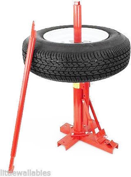
Follow all safety instructions in this guide, on the machine and machines manual.
1. Once tire pressure is indicated on the air gauge (inflation pedal in position 1; foot removed from pedal), continue to inject air into the tire in short intervals. Check the pressure frequently. Stand back during bead seat. Keep hands, arms, and entire body away from tire during this procedure. Tire beads should move outward and "pop" into their bead seat position as pressure inside the tire increases. If this does not happen, a problem exists. Investigate carefully.
Check tire pressure frequently. Never exceed 40 PSI while seating beads. Once seated, never exceed tire manufacturer's recommended air pressure. Tires can explode, especially if they are inflated beyond their limits. At all pressure levels when inflating through the valve stem, keep hands, arms, and entire body away from inflating tire.
An exploding tire, wheel, or bead sealing equipment may propel upward and outward with sufficient force to cause serious injury or death to operator or bystander.
Inflation NEVER exceed tire manufacturer's recommended air pressure. Tires can explode, especially if inflated beyond these limits. Keep hands, arms, and entire body back from inflating tire. Avoid distraction during inflation. Check tire pressure frequently to avoid over inflation. Excessive pressure can cause tires to explode, causing serious injury or death to operator or bystander.
THE RIM MUST BE UNCLAMPED WHEN INFLATING BUT ONLY AFTER BEADS HAVE BEEN SEATED.
The machine is equipped with an inflation gauge for monitoring the inflation of the tire and the inflation pressure.
1. Connect the inflation hose with the tire air core. Make sure both beads are seated. When both beads are seated, the tire is ready for inflation.
2. Replace the valve core if it was removed.
3. Depress the inflation pedal to position 2 to inflate the tire. Release air pressure from tire by pressing the manual release valve button (inflation hose must be attached to the valve stem).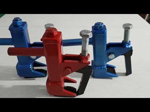
STAGES OF INFLATION - Images Review these descriptions and diagrams carefully. Refer to them as necessary during bead sealing, bead seating, and inflation to verify that you are proceeding properly and safely.
Bead Sealing
A 140 PSI air blast from the table top jets creates an air curtain to aid in bead sealing. Never exceed 10 PSI in the tire during bead sealing. The tire will contain about 1/2 to 2 PSI when bead seal is obtained. Bead Seal - Hold the tire against the top bead seat and use the bead blast air jets to seal the bottom bead.
Bead Seating
Bead seating usually occurs on the long tapered side of the wheel first and the shorter side last. Bead seating will usually require at least 7 PSI in the tire. 40 PSI is the maximum safe pressure at this stage regardless of tire operating pressure. Most European import cars and many aftermarket alloy wheels are very tight and can be difficult to bead seat. Also note that asymmetrical hump and run-flat tires are extremely difficult to bead seat. Follow tire manufacturer's recommended procedure for bead seating. Usually last to "pop" is top side Do not stand over tire during inflation. Requires visual confirmation of bead seat. Bead seating is confirmed when both beads have popped in place and are visually checked.
Inflation
After the beads are seated, the tire is inflated. Do not inflate the tire above the manufacturer's recommended pressure as stamped on the tire sidewall. The typical inflation pressure for automobile tires is between 24 and 45 PSI. Light truck inflation pressure typically covers a wider range.
Do not stand over tire during inflation. Requires rubber lubricant on both upper and lower beads Air flow through valve requires about 140 PSI air pressure drop to insure sufficient flow on difficult tires. Table top jets Lift tire up to assist seal on top side.
DANGER! BEWARE!
MISMATCHED TIRES AND WHEELS Never attempt to mount and inflate mismatched tires and wheels. Mismatched tire and wheel combinations explode, causing personal injury or death to operator and bystanders. For safety, do not attempt to mount and inflate mismatched tires and wheels.
Half Size Tires 14.5, 15.5, 16.5, 17.5, etc.
MISMATCH
Even Size Wheels 14.0, 15.0, 16.0, 17.0, etc.
Even Size Tires 14.0, 15.0, 16.0, 17.0, etc.
MISMATCH
Half Size Wheels 14.5, 15.5, 16.5, 17.5, etc.
READ… Mounting and inflating the wrong size tire can get you hurt. Read the size on the tire and make sure it matches the rim. Be especially careful about putting a smaller tire on a larger rim and vice versa, such as a 16-inch tire on a 16.5-inch rim or a 16.5" tire on a 16" rim. Inflation of a mismatched tire and rim can cause an explosion.
INSPECT… Before you put any tire on a rim, inspect the rim for rust, tough spots, bent edges, or cracks that could prevent the tire from seating right. If you spot any of these problems, don’t mount the tire until the rim has been checked by your shop foreman. Inspect the tire for bead damage.
MOUNT… Once you’ve made sure the tire is OK and the right size and the rim is OK, mount the tire safely.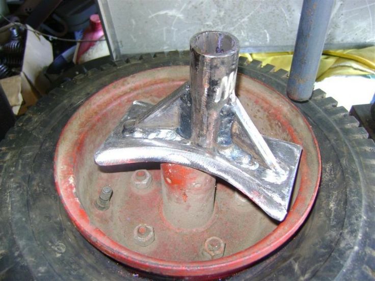 NEVER, ever lean over the tire when you’re inflating it. If a tire does explode, it will go straight up. You don’t want to be over the tire if that happens. Also, never over-inflate the tire, even if the bead doesn’t seat. Never inflate over 40 PSI. If the tire wasn’t seated, something is wrong. Deflate the tire and check it and the rim again. If it doesn’t work the second time, try another tire.
THE OWNER IS RESPONSIBLE FOR MAINTAINING THE OPERATION INSTRUCTIONS AND DECALS FOR HIS MACHINE AS WELL AS PROVIDING THEM TO ALL OPERATORS.
For more information contact:
Rubber Manufacturers Association
1400 K Street N. W., Suite 900
Washington, DC 20005
(202) 682-4800
www.rma.org
Tire Guides, Inc.
The Tire Information Center
1101-6 South Rogers Circle
Boca Raton, FL 33487-2795
(561) 997-9229
www.tireguides.com
Tire Pellet or Powder Processing Plant
Our company's pneumatic tire processing equipment is highly flexible in use, so how it is able to process and grind any type of pneumatic tires into granules. Tire recycling begins with the removal of steel cord from the tire beads. Then the tires, moving along the line, enter the shredder, which crushes the pneumatic tires into chips for their subsequent processing.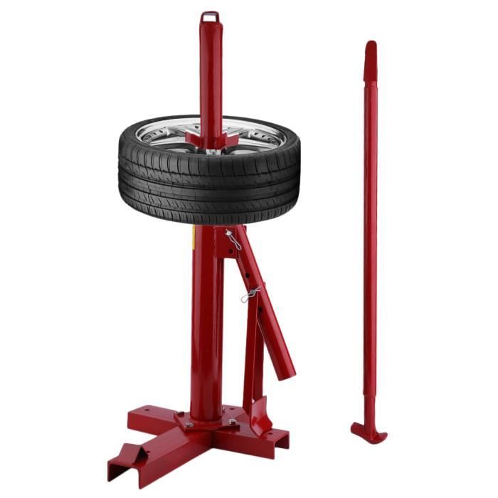 At the end of the whole process, the crushed chips are sent to the granulation operation by means of a conveyor belt. In the mill, the chips are crushed to the smallest granules. nine0007
Our company can offer a technological solution for obtaining various degrees of grinding tires to crumbs or powder ranging in size from 5 mm to 500 microns. The size of the crumb can be adjusted in accordance with the most diverse requirements of the Customer. Thanks to the separation system, specially developed by the company's specialists, there is almost no textile fiber in the granules.
Capacity: from 1 to 6 t/h.
Inlet: pre-treated car and truck tires
Output: granules or powder with a diameter of 5 mm to 500 µm.
The proposed technology and design is based on extensive waste processing experience. The proposed equipment includes a full cycle of the recycling process - from whole tires to the production of high-turnover granular rubber. All shredders have a solid construction. High speed equipment with dynamically balanced rotors is used for fine grinding. Equipment components subjected to the greatest abrasion are made of wear-resistant steel. The most loaded parts are coated with Swedish tool steel, which shows the minimum abrasion after 1000 hours of operation. Knives are very easy to replace if necessary. Low speed blades can be resharpened after they become dull and used for further chopping. The place for low speed knives is protected from abrasion by rotating the plates towards the knife, which reduces wear on the material on the stationary wall. The high speed fine chopping knives allow you to use all four sides of the knife. Knives can be sharpened at least four times, which has a positive effect on the price and, in general, on the process of saving. nine0007
The grinding process equipment is divided into the following:
Pre-crushing line
The staff sends the tires by conveyor to the twin shaft low speed shredder.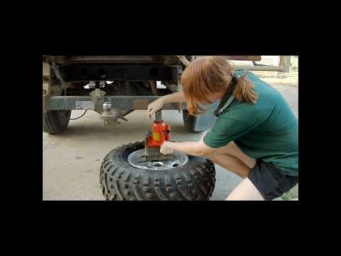 This shredder is specially designed for shredding tires. The shredder has easily replaceable knives without dismantling the shredder. Knives are made of special tool steel. Tires are pre-crushed into chips about 50 mm in size. The crumb rubber then enters a sieve which returns pieces over 50mm back to the low speed shredder. The crushed material is transported to a filling tank. nine0007
Grinding to obtain 20-30 mm chips
The crumb from the tank is transferred to the mill in a precisely adjusted quantity per hour. Mill power • 200 kW, equipped with 28 mm screen. The first separation of the metal takes place in the mill. After the first separation, the rubber contains a maximum of 1×5% metal. The crumb rubber produced by the mill is suitable as a substitute for fuel, for example, in cement plants.
Fine grinding for crumbs 0-4 mm
After metal separation, the material enters the first mill. The blades of the mill are made of a special material capable of grinding mixed material containing residual metals. The mill is equipped with a sieve, due to which the fraction at the outlet is about 10 mm. Just like the first mill, the G mill is provided with a protective coating. Rubber crumb is transported by a pneumatic cyclone. The second mill G is equipped with a sieve, the output fraction is about 4 mm. Double metal separation takes place in this part of the line. The crumb is transported by means of a pneumatic cyclone, consisting of a fan, pipeline, cyclone and a dust and textile remover. The outgoing crumb enters the big bags. nine0007
Full cycle tire recycling plant
Our partners have developed a technological solution that not only processes tires into crumb rubber, but also developed a system for the useful and profitable use of steel from recycled tires. Previously, in many plants, this material was considered only as waste or material difficult to recycle. Recycling steel is as important as obtaining high-quality rubber crumb or powder. Rubber crumb, which is a recyclable material obtained from tire recycling, can be quickly sold both in the Russian and European markets and is used as:
• Highway top coat (asphalt additives).
• Industrial rubber goods for machines.
• raw rubber and reclaimed rubber.
• rubber mats (under the door and in the bathroom).
• Bumps for the road (speed bump).
• railroad sleeper pads.
• gaskets for railway rails and railway fittings.
• foam rubber.
• coating for sports fields.
• poured seamless coatings. nine0007
• shoe soles.
• Novotrack covers.
• sanitary gaskets.
• rubber roofing and pavers.
• ERDM granules.
• tread band for wheel restoration
• gaskets and seals for doors and windows.
• for quay fenders.
• coatings for sports fields, etc.
| Specifications | Units | |
| Shredder ST 1300/50 150kW | ||
| Crushing area dimensions | mm | 1300x1150 |
| Blade width | mm | 100, 90, 80, 70 |
| Rotor rotation | rpm | nine0129 20|
| engine start | - | 2 planetary gearboxes |
| Power | kW | 150 |
| Number of rotor holders/knives | pcs | 18/432 |
| Output shaft power | kWh | 75+75 |
| Performance | t/h | 5 – 15 |
| Minimum hydraulic unit power | kWh | 3 |
| Weight | t | 15 |
| Torque | Nm | 100000 |
| Dimensions (W x D x H) | mm | nine0129 3000x5000x3000|
| Mill GH 600/1200-6/6/28 | ||
| Rotor diameter | mm | 600 |
| Rotor length | mm | 1200 |
| Rotor rotation | rpm | 500 |
| Motor power | kWh | nine0129 200|
| Motor rotation | rpm | 1470 |
| Number of knives per rotor | pcs | 24 |
| Number of knives to replace | pcs | 12 |
| Material output including dust (output 70x70mm) | t | 2-3 | nine0137
| Minimum hydraulic unit power | to | 0.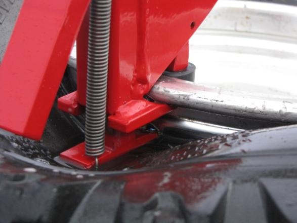 37 37 |
| Weight | t | 10 |
| Dimensions (W x D x H) | mm | 2500x4000x3000 |
| Mill G 600/1200-7/4/10 | ||
| Rotor diameter | mm | 600 |
| Rotor length | mm | 1200 |
| Rotor rotation | rpm | 500 |
| Motor power | kWh | 90 |
| Motor rotation | rpm | 1470 |
| Number of knives per rotor | nine0129 pcs14 | |
| Number of knives to replace | pcs | 8 |
| Material output including dust (output 70x70mm) | t | 2 |
| Minimum hydraulic unit power | to | 0.37 |
| Weight | t | nine0129 8|
| Dimensions (W x D x H) | mm | 2500x4000x3000 |
| Mill G 600/1200-7/4/4 | ||
| Rotor diameter | mm | 600 |
| Rotor length | mm | 1200 |
| Rotor rotation | rpm | 500 |
| Motor power | kWh | 90 |
| Motor rotation | rpm | 1470 |
| Number of knives per rotor | pcs | 14 |
| Number of knives to replace | pcs | 8 |
| Material output including dust (output 70x70mm) | t | 1.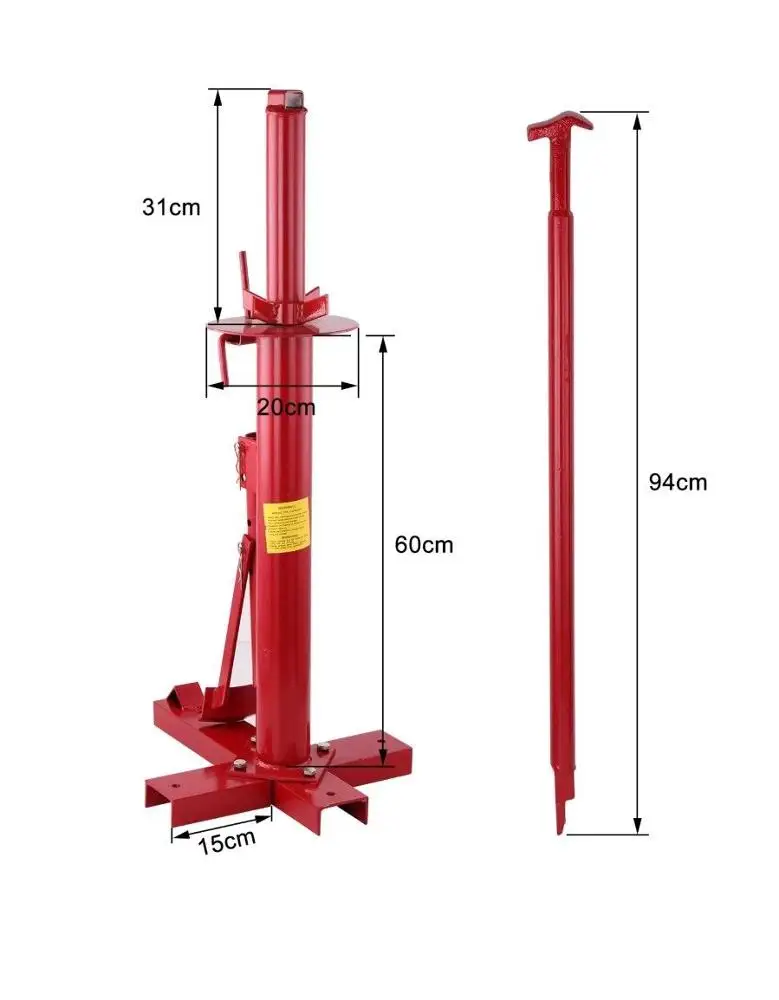 5 5 |
| Minimum hydraulic unit power | to | 0.37 |
| Weight | t | 8 |
| Dimensions (W x D x H) | mm | 2500x4000x3000 |
| Mill G 600/1200-7/4/3 | ||
| Rotor diameter | mm | 600 |
| Rotor length | mm | 1200 |
| Rotor rotation | rpm | 500 |
| Motor power | kWh | 90 |
| Motor rotation | rpm | 1470 | nine0137
| Number of knives per rotor | pcs | 14 |
| Number of knives to replace | pcs | 8 |
| Material output including dust (output 70x70mm) | t | 1 |
| Minimum hydraulic unit power | to | 0.37 | nine0137
| Weight | t | 8 |
| Dimensions (W x D x H) | mm | 2500 x 4000 x 3000 |
Plant for processing tires or powder 9000,
9000 as it is able to process and grind any type of pneumatic tires into granules. Tire recycling begins with the removal of steel cord from the tire beads. Then the tires, moving along the line, enter the shredder, which crushes the pneumatic tires into chips for their subsequent processing. At the end of the whole process, the crushed chips are sent to the granulation operation by means of a conveyor belt. In the mill, the chips are crushed to the smallest granules. nine0007
Our company can offer a technological solution for obtaining various degrees of grinding tires to crumbs or powder ranging in size from 5 mm to 500 microns. The size of the crumb can be adjusted in accordance with the most diverse requirements of the Customer. Thanks to the separation system, specially developed by the company's specialists, there is almost no textile fiber in the granules.
Capacity: from 1 to 6 t/h.
Inlet: pre-treated car and truck tires
Output: granules or powder with a diameter of 5 mm to 500 µm.
The proposed technology and design is based on extensive waste processing experience. The proposed equipment includes a full cycle of the recycling process - from whole tires to the production of high-turnover granular rubber. All shredders have a solid construction. High speed equipment with dynamically balanced rotors is used for fine grinding. Equipment components subjected to the greatest abrasion are made of wear-resistant steel. The most loaded parts are coated with Swedish tool steel, which shows the minimum abrasion after 1000 hours of operation. Knives are very easy to replace if necessary. Low speed blades can be resharpened after they become dull and used for further chopping. The place for low speed knives is protected from abrasion by rotating the plates towards the knife, which reduces wear on the material on the stationary wall. The high speed fine chopping knives allow you to use all four sides of the knife. Knives can be sharpened at least four times, which has a positive effect on the price and, in general, on the process of saving. nine0007
The grinding process equipment is divided into the following:
Pre-crushing line
The staff sends the tires by conveyor to the twin shaft low speed shredder. This shredder is specially designed for shredding tires. The shredder has easily replaceable knives without dismantling the shredder. Knives are made of special tool steel. Tires are pre-crushed into chips about 50 mm in size. The crumb rubber then enters a sieve which returns pieces over 50mm back to the low speed shredder. The crushed material is transported to a filling tank. nine0007
Grinding to obtain 20-30 mm chips
The crumb from the tank is transferred to the mill in a precisely adjusted quantity per hour.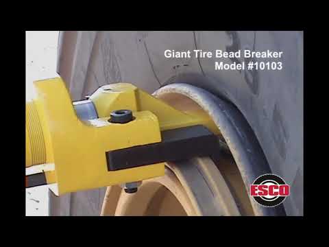 Mill power • 200 kW, equipped with 28 mm screen. The first separation of the metal takes place in the mill. After the first separation, the rubber contains a maximum of 1×5% metal. The crumb rubber produced by the mill is suitable as a substitute for fuel, for example, in cement plants.
Fine grinding for crumbs 0-4 mm
After metal separation, the material enters the first mill. The blades of the mill are made of a special material capable of grinding mixed material containing residual metals. The mill is equipped with a sieve, due to which the fraction at the outlet is about 10 mm. Just like the first mill, the G mill is provided with a protective coating. Rubber crumb is transported by a pneumatic cyclone. The second mill G is equipped with a sieve, the output fraction is about 4 mm. Double metal separation takes place in this part of the line. The crumb is transported by means of a pneumatic cyclone, consisting of a fan, pipeline, cyclone and a dust and textile remover.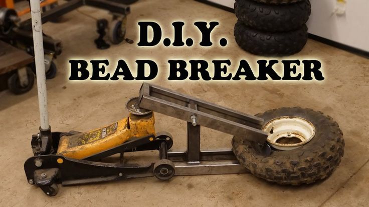 The outgoing crumb enters the big bags. nine0007
Full cycle tire recycling plant
Our partners have developed a technological solution that not only processes tires into crumb rubber, but also developed a system for the useful and profitable use of steel from recycled tires. Previously, in many plants, this material was considered only as waste or material difficult to recycle. Recycling steel is as important as obtaining high-quality rubber crumb or powder. Rubber crumb, which is a recyclable material obtained from tire recycling, can be quickly sold both in the Russian and European markets and is used as:
• Highway top coat (asphalt additives).
• Industrial rubber goods for machines.
• raw rubber and reclaimed rubber.
• rubber mats (under the door and in the bathroom).
• Bumps for the road (speed bump).
• railroad sleeper pads.
• gaskets for railway rails and railway fittings.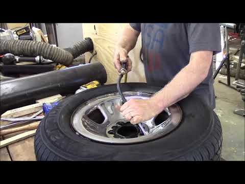
• foam rubber.
• coating for sports fields.
• poured seamless coatings. nine0007
• shoe soles.
• Novotrack covers.
• sanitary gaskets.
• rubber roofing and pavers.
• ERDM granules.
• tread band for wheel restoration
• gaskets and seals for doors and windows.
• for quay fenders.
• coatings for sports fields, etc.
| Specifications | Units | |
| Shredder ST 1300/50 150kW | ||
| Crushing area dimensions | mm | 1300x1150 |
| Blade width | mm | 100, 90, 80, 70 |
| Rotor rotation | rpm | 20 |
| Engine start | - | 2 planetary gearboxes |
| Power | kW | 150 |
| Number of rotor holders/knives | pcs | 18/432 |
| Output shaft power | kWh | 75+75 |
| Capacity | t/h | nine0129 5 – 15|
| Minimum hydraulic unit power | kWh | 3 |
| Weight | t | 15 |
| Torque | Nm | 100000 |
| Dimensions (W x D x H) | mm | 3000x5000x3000 |
| Mill GH 600/1200-6/6/28 | ||
| Rotor diameter | mm | 600 |
| Rotor length | mm | 1200 |
| Rotor rotation | rpm | 500 |
| Motor power | kWh | 200 |
| Motor rotation | nine0129 rpm1470 | |
| Number of knives per rotor | pcs | 24 |
| Number of knives to replace | pcs | 12 |
| Material output including dust (output 70x70mm) | t | 2-3 |
| Minimum hydraulic unit power | nine0129 to 0.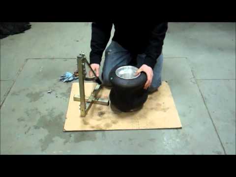 37 37 | |
| Weight | t | 10 |
| Dimensions (W x D x H) | mm | 2500x4000x3000 |
| Mill G 600/1200-7/4/10 | ||
| Rotor diameter | mm | 600 |
| Rotor length | mm | nine0129 1200|
| Rotor rotation | rpm | 500 |
| Motor power | kWh | 90 |
| Motor rotation | rpm | 1470 |
| Number of knives per rotor | pcs | 14 |
| Number of knives to replace | pcs | 8 |
| Material output including dust (output 70x70mm) | t | 2 |
| Minimum hydraulic unit power | to | 0.37 |
| Weight | t | 8 |
| Dimensions (W x D x H) | mm | nine0129 2500x4000x3000|
| Mill G 600/1200-7/4/4 | ||
| Rotor diameter | mm | 600 |
| Rotor length | mm | 1200 |
| Rotor rotation | rpm | 500 |
| Motor power | kWh | nine0129 90|
| Motor rotation | rpm | 1470 |
| Number of knives per rotor | pcs | 14 |
| Number of knives to replace | pcs | 8 |
| Material output including dust (output 70x70mm) | t | 1.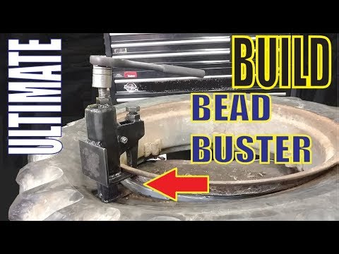 5 5 | nine0137
| Minimum hydraulic unit power | to | 0.37 |
| Weight | t | 8 |
| Dimensions (W x D x H) | mm | 2500x4000x3000 |
| Mill G 600/1200-7/4/3 | ||
| Rotor diameter | mm | 600 | nine0137
| Rotor length | mm | 1200 |
| Rotor rotation | rpm | 500 |
| Motor power | kWh | 90 |
| Motor rotation | rpm | 1470 |
| Number of knives per rotor | piece | 14 |
| Number of knives to replace | pcs | 8 |
| Material output including dust (output 70x70mm) | t | 1 |
| Minimum hydraulic unit power | to | 0. 37 37 |
| Weight | t | nine0129 8|
| Dimensions (W x D x H) | mm | 2500 x 4000 x 3000 |
Rating:
Continue
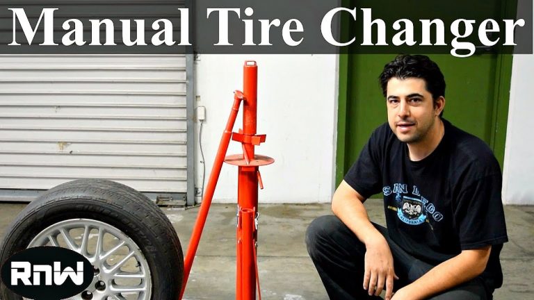
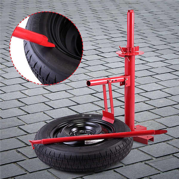
Today, car owners are accustomed to turning to a tire shop in case of problems with their wheels. But such services can only be found in big cities, and there are many "deaf" places where it is difficult to find a tire repair shop. In such a situation, a spare tire can help the driver out, but sometimes problems happen with several tires at once. Therefore, the car owner must know how the wheels are beaded with their own hands. Moreover, many drivers do not trust the mechanics of tire services, and prefer to do such work on their own. nine0007
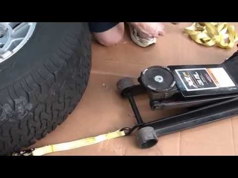
This is one of the easiest ways to take apart and bead a wheel yourself. If you follow the instructions below, you can easily do this work with your own hands.
 nine1278
 Attention! If the nipple is working, then it can be unscrewed and used for a new camera, or put in stock.
Bead work takes less time and effort, but it also needs to be done in a certain order.
Now it remains to install the nipple, inflate the tire to the pressure required by the manufacturer, and put the wheel on the car.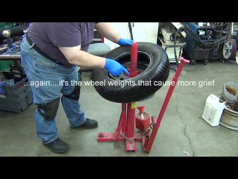

 8")
8") ..
.. These are excellent: useful, non-marring. lightweight.