Article Category:
Maintenance
What part on your aircraft hasn’t changed its design in over 100 years? Sounds like a good trivia question, doesn’t it? The answer: it’s the Schrader valve. Whether your tires are tubeless or have a tube, there’s a tire valve on every wheel, a design patented in 1898.
Without August Schrader and his son, George, there wouldn’t have been an easy way to put air into your tires
and keep it there. The Schrader-valve has been an American standard for 102 consecutive years and a world standard for more than 76 years. George Schrader is credited with the pioneering effort and experimental work that resulted in patents issued for the current housing design with its removable and interchangeable core and cap.
Additionally, if you fl y an aircraft, you most assuredly have many valve cores on many different components of your aircraft. Probably the most common places you would find these would be in places such as the landing gear on the tires and tubes and on any shock strut’s. However the valve cores are used in many other aviation and industrial applications such as hydraulic systems, pneumatic systems, air conditioning systems, and fuel systems and, if you look, you’ll even see them on the top of your fire extinguisher.
These valve cores are often referred to as Schrader valves- named, of course, after the inventor. Schrader International is the manufacturer that sells most of the valve cores used today.
This valve consists of an externally threaded hollow cylindrical metal tube. In the center is a metal pin running along the axis of the outer cylinder attaching to the cup seal on the pressure end of the valve. This valve is nothing more than another version of a check valve. The body of the valve cores are normally brass, stainless steel or nickel plated steel. There are many different types of valve cores that are used throughout the industry and we often find them, intended for other applications, installed in aircraft struts or even aircraft tires.
One of the most common errors made is selecting a valve core intended for a tire, but used for a landing gear strut.
Even on small aircraft, the pressures that exist inside of a landing gear strut, especially on landing, are quite high compared to that of a typical tire. The typical Schrader valve that we find in aviation tire applications is usually part number 6035 which has a standard operating pressure from 0 to 400 PSI and a normal operating pressures normally not over 70 PSI. However, the typical Schrader valve that we should find in an aviation shock strut or hydraulic accumulator should be Schrader part number 2300TV.
This valve has an operating pressure from 0 to 2000 PSI. If you’re unfamiliar with each of these types of valve cores, there are a couple of items that can help you identify their proper application. On high-pressure valve cores it is common to see on the stem the letter H stamped into the head of the valve pin. This is not easy to see with the naked eye but a magnifying glass soon reveals a very distinctive letter “H”. In addition, the plug sealing material is made from a black molded nitrile rubber. The plunger sealing material is typically a black nitrite material. On the other hand, a valve core used in an aviation tire application typically has a white silicone plunger sealing material around the outside with a natural Tefl on plug sealing material.
Many home built, light sport and ultralight aircraft use valve cores made for general purpose and commercial applications. These valve cores can have a white silicone or a black nitrite plunger sealing material with a red or green Tefl on plug sealing material.
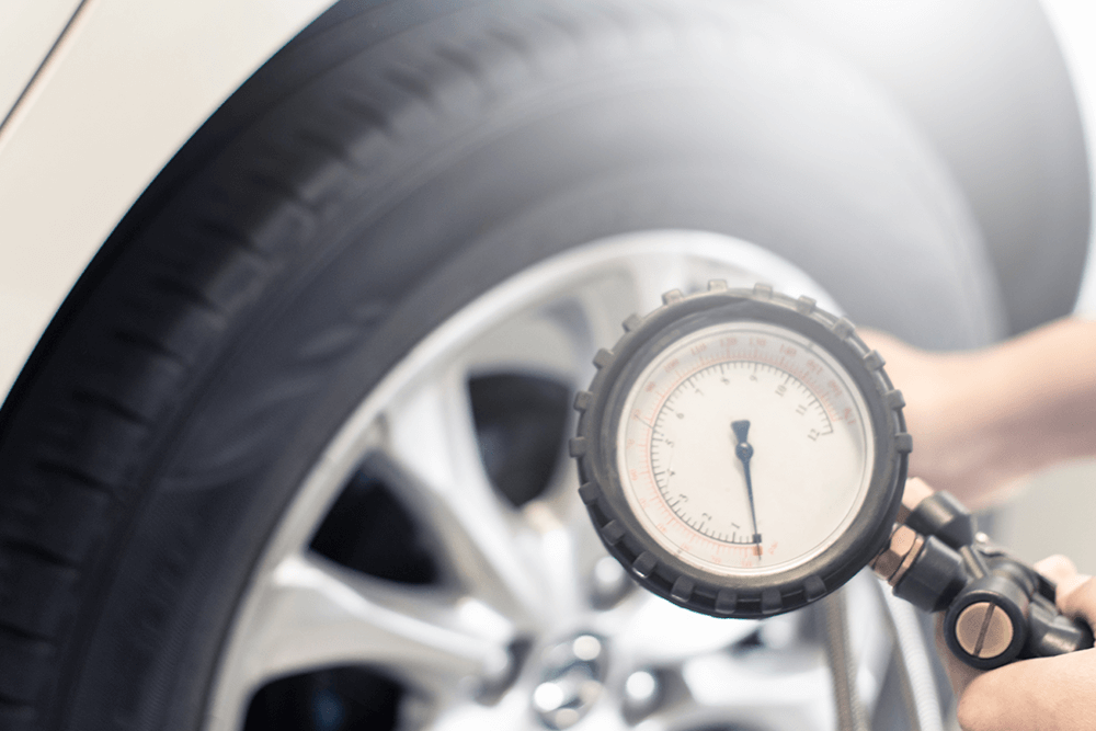
These are adequate for many of these applications, however, they are designed for operating pressures from 0 up to 200 PSI One of the most common reasons for a valve core to start leaking is due to contamination entering down into the valve stem. This is the primary reason for using a valve cap on your tires and on the top of the Schrader valve located on your landing gear strut. Even a minute amount of dirt can get underneath the sealing surfaces of the valve causing a leak. In the case of a tire or strut, it may take several days, or as little as a few minutes, to leak down.
It is important to recognize that both the plug sealing material and the plunger sealing material are made of components such as Tefl on, silicon, nitrite rubber or nitrile rubber.
All of these materials are life limited and will deteriorate with age, heat and exposure to oxygen (this is one of the reasons that we use nitrogen to service tires, and struts.) If you find that you are having a slow leak on a landing gear strut, one of the easiest troubleshooting tools you have is to simply replace the valve core and see what kind of results you get. If you keep your landing gear valve stems on your tubes covered with a valve cap, it is likely that your valve core will outlast the rubber on the tube. However, on tubeless tires we often see the valve core remaining with the rim for thousands of hours, and in this case, eventually will see deterioration of the valve core.
Generally, all Schrader valves used on tires have threads and bodies of a single standard size at the exterior end, so caps and tools generally are universal for the valves on all common applications.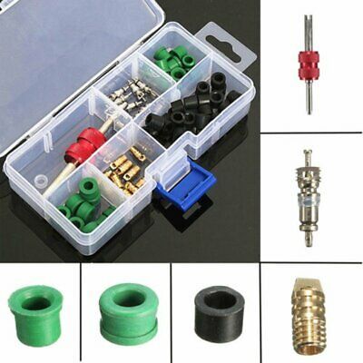 Removing, installing or replacing a valve core is inexpensive and easy to do. You will just need the replacement valve core and a valve core tool. These are readily available from any auto parts store.
Tips for installation of the valve core: There is a specific torque called out for the installation of a valve core between 2 - 5 inch pounds. As you can see, it doesn’t take much to torque.
Make sure that you don’t strip out the threads while installing a new valve core and don’t over tighten the valve stem core when installing the new one. When the top portion of the Schrader breaks off in the service port, the section that’s left behind resembles a hollow barrel. They are difficult to remove since there is nothing to grab a hold of. Rather than scrap the part, a T15 TORX driver can be used to extract the barrel. With a light tap, the teeth on the driver bite into grip the soft brass of the broken Schrader valve.
And finally, any time that a valve core is removed from the valve body, it is standard practice, to install a new valve core and discarded the old one. This is also consistent with the manufacturer’s recommendations.
For more information
www.rainbowaviation.com
Toll-free: 877-7-FLY-LSA
or 530-824-0644
Light Aviation Edition September 2010
To view this article in original digital format, click the link below:
http://viewer.zmags.com/publication/b55bd6aa#/b55bd6aa/16
Documents:
HALTEC
 Model # A-100-VC-1
 Country of Origin China. Country of Origin is subject to change.
Heat-Resistant Core can be used in most cars, trucks, and buses that have a standard bore.
Tap image to zoom.
Roll over image to zoom.
HALTEC
Country of Origin China. Country of Origin is subject to change.
Heat-Resistant Core can be used in most cars, trucks, and buses that have a standard bore.
Contents:
Two types of valves are most commonly used in the control of liquid and gaseous media in modern industrial plants: solenoid valves and pneumatically actuated valves. The sheer number of different valve models of both types, designed for a wide variety of applications, has led to the fact that the choice between a solenoid (electromagnetic) valve and a valve with an air actuator is no longer obvious.
This article discusses the design features of both types of valves and how these features affect valve selection and operation. The described phenomena and the conclusions obtained are practically valid. for all valves, regardless of model or manufacturer, since the causes of these phenomena are concentrated in the very principle of operation of the valves of the types in question.
The device of the simplest solenoid valve is shown in Figure 1.
Figure 1 - The design of the direct-acting solenoid valve The coil (1) is installed on the core tube (2), inside which is the core (3), pressed against the valve seat (5) by a spring (four).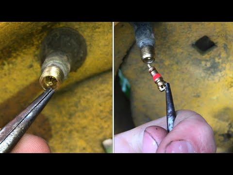 When voltage is applied to the coil, an electromagnetic field is created inside it and, accordingly, inside the core tube, as a result of which the core rises, opening the passage of fluid through the valve seat.
Thus, valves of this type work due to the electromagnetic field generated by the coil. The coil itself is often called a solenoid, hence the name of the valve - "solenoid" or "electromagnetic". Since the electromagnetic field of the coil acts directly on the core that closes the valve bore, such electromagnetic valves are called direct acting valves.
Direct acting solenoid valves become more difficult as they are increased in size to accommodate higher fluid flow. This is due to the dramatic increase in coil retraction force required to lift the core and open the valve.
Example of calculating the force required to retract the core
In general, for any homogeneous liquid or gaseous medium, pressure is related to force as follows:
P=FS(1),P= {F} over {S }, ~( 1 )
where:
Р – medium pressure;
F is the force exerted by the medium on the surface;
S - surface area.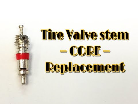
Since the valve seat is circular, the area is calculated using the following formula: 92 } over {4}. ~( 3 )
This formula is used to calculate the force with which the water inside the valve presses the core against the seat at a given pressure P and seat diameter d. Let's calculate this value for the GEVAX solenoid valve 1901R-KDVD006-050-24DC (Direct acting solenoid valve, brass, 1/2" (5 mm), 2/2 NC, -10°С...+130°С, 0...6 bar, 24V= , FPM seals). Data for calculation are given in the valve passport: maximum pressure working medium P = 6 bar, bore diameter d = 5 mm. Substituting these values into formula (3), we get: 92 } over {4}=11.8 N. ~( 4 )
For correct operation of the solenoid valve, the core retracting force caused by the electromagnetic field of the coil must be greater than the pressing force of the core to the seat. To ensure such an effort, an AMISCO EVI 5P / 13 coil with a power of W 1 \u003d 17 W is installed on the valve.
Let's make a similar calculation for a 2" solenoid valve (50mm seat diameter) with a working pressure of 10 bar. Then we find that the minimum retraction force should be: 92} times {{A} over {2 times %mu_0}, ~( 6 )
where:
I is the current consumed by the coil;
N - the number of turns of wire inside the coil;
µ r — magnetic permeability of the core;
µ 0 – magnetic constant equal to 4π 10 -7 H/m;
L - the length of the winding of the wire inside the coil;
A is the cross-sectional area of the core.
The power W consumed by the coil from the electrical network is: 92 times %mu_0 times R } ~( 9 )
Then the formula for the coil pulling force will take the following form
F=W×Kcc(10)F=W times K_cc ~( 10 )
The retracting force of the coil depends on the design of the coil-core valve assembly and is proportional to the electrical power drawn by the coil.
Consider two solenoid valves with coils of different power but the same coil and core design. Then the pulling force F 1 and F 2 and power consumption W 1 and W 2 will be related as follows:
F1W1=F2W2(11){F_1} over {W_1} = {F_2} over {W_2} ~( 11 )
Expressing from this equality W 2 we get: retracting force F 1 calculated by formula (4), F 2 calculated by formula (5) and nameplate power value of the coil AMISCO EVI 5P/13 W 1 = 17 W, we get:
W2=W1F2F1=17W1962.5H11.8H=2827W≈3kW(13){ {W_2} = W_1 {F_2} over {F_1} =17W {1962.5H} over {11 ,8N} =2827W approx 3 kW ~( 13 )
We have thus calculated the coil power required to operate a direct acting solenoid valve with a seat diameter of 50 mm and an operating pressure of 10 bar. Of course, these calculations are approximate, however, the order of the values obtained is correct. Obviously, the use of coils of such power is unjustified.
However, there are solenoid valves that meet the conditions of the task, but with coils whose power does not exceed 10 - 20 W. The fact is that these valves have a different design, described below.
In order to reduce the energy consumption of large diameter solenoid valves and to work with high pressures, the design of the indirect acting solenoid valve has been developed, shown in Figure 2a.
Figure 2 - Construction and operation of floating diaphragm solenoid valvesIn such solenoid valves, the main flow area is blocked by a diaphragm that is pressed against the seat. The opening of the valve is carried out by lifting the membrane, caused by the redistribution of the pressure of the working medium in the zones above the membrane and below the membrane.
In the initial state (see figure 2a), the valve coil is not energized. The liquid entering the solenoid valve inlet, through a small bypass hole in the membrane, penetrates into the area above the membrane. The surface area of the membrane with which the fluid interacts is greater in the area above the membrane than in the area below the membrane. If the pressures above and below the diaphragm are equal, this results in a force that presses the diaphragm against the valve seat. One of the key design elements that affects the operation of the solenoid valve is the bypass. Its location on the diagram and photograph are shown in Figure 2b.
Applying voltage to the coil (see figure 2c) causes the core to rise. As a result, liquid from the area above the membrane through the pilot hole begins to flow to the outlet of the solenoid valve. The diameter of the pilot port is larger than the diameter of the bypass port, so the pressure over the diaphragm decreases and the diaphragm itself rises to open the main passage of the valve.
The diaphragm is lifted by the pressure of the fluid entering the valve inlet, so valves of this design cannot operate at low medium pressure. pressure difference between inlet and outlet as a rule, should be at least 0.3 - 0.5 bar. This parameter is indicated in the technical characteristics of the solenoid valve.
As long as the coil is energized (see figure 2d), the core is up and the pilot hole is open. This leads to the fact that the pressure above the membrane and the elastic force of the compressed spring becomes less fluid pressure under the membrane. As a result, the membrane remains raised and the valve is open.
When the coil is de-energized (see Figure 2e), the core springs down and closes off the solenoid valve pilot hole. The liquid ceases to leave the area above the membrane, as a result of which the pressure in this zone increases and becomes equal to the pressure of the liquid under the membrane (at the valve inlet). Under the action of the elastic force of the compressed spring, the membrane begins to fall, blocking the passage of fluid through the valve.
After the valve is closed (see figure 2e), the diaphragm is pressed tightly against the seat by the force caused by the fluid pressure and the differential wetted area of the diaphragm.
In the above process, when the solenoid valve is opened, the diaphragm is lifted by the action of the liquid - "floats", therefore valves of this design are often called floating solenoid valves. membrane.
Floating Diaphragm Valve Examples
The described operating principle is valid for normally closed (NC) solenoid valves. Normally open (NO) solenoid valves are similar, but the pilot port is normally open and closes when the coil is energized. The membrane of these valves also rises as a result of fluid pressure applied to it. Thus, if the differential pressure ΔP is less than the minimum allowable ΔP min , the diaphragm will close the main valve passage, but the pilot port will be open. Therefore, at ΔP min NO, the valve will open, but the flow through it will be significantly less than in the operating mode, when ΔP > ΔP min .
Floating diaphragm solenoid valves work correctly at ΔP min max. At ΔP min, the valves operate, but the flow rate of the working medium through them is much less than the nominal one.
Another common design of indirect acting solenoid valves is positive lift diaphragm valves. It is shown in Figure 3. The principle of operation of these valves is similar to those previously discussed.
Figure 3 - The design and principle of operation of solenoid valves with forced lifting diaphragmIn the initial state (see Figure 3a), the valve coil is not energized. Fluid entering the valve inlet through a small bypass hole penetrates the area above the diaphragm and presses the diaphragm against valve seat.
Applying voltage to the coil (see figure 3b) causes the core to rise. Through the pilot hole, fluid begins to flow to the valve outlet and the pressure above the membrane drops.
The diaphragm rises due to the pressure difference above and below it, opening the main orifice of the solenoid valve (see figure 3c).
In contrast to the previously discussed valves, solenoid valves with positive lift diaphragm can be operated without differential pressure (ΔP = 0 bar). In such a situation, the membrane is lifted due to the force of the electromagnetic coil, which retracts the core. It lifts the membrane connected to the core by a spring.
The ability of these valves to operate without differential pressure has led to them being often erroneously referred to as direct acting valves. A more correct name - solenoid valves with a forced lifting membrane - is due to the fact that in the absence of pressure, the membrane is forced up (regardless of the working medium) due to the force created by the electromagnetic field of the coil.
Examples of floating diaphragm valves
The three most common solenoid valve designs have been discussed above. However, they all have the following in common:
 As a rule, this is one of the types of rubber: NBR - nitrile butadiene, EPDM - ethylene-propylene or FPM - fluorine.
 If a clean and homogeneous medium without any impurities passes through the valve, it will hardly affect the operation of the solenoid valve itself. However, if the medium is contaminated and contains finely dispersed elements (for example, water with rust impurities), these particles eventually settle on the core and the walls of the core tube. Contamination of the core tube can cause the core to become stuck inside it, causing the valve to stick (see Figure 4). In this case, the solenoid valve can remain both open and closed.
Figure 4 - Valve core stuck due to contamination Also, direct contact of the working fluid with the core tube ensures good heat exchange between them. Therefore, if a hot medium (steam or hot water) passes through the solenoid valve, the core will heat up, causing heating of the coil and accelerated aging of the interturn insulation. As a rule, coils of solenoid valves designed for steam service have a high thermal insulation class (F or H). Despite this, overheating and further burnout of the steam valve coil is not is something unusual and occurs quite often.
In cases where a cold medium (such as chilled propylene glycol solution) passes through the solenoid valve, the core tube is cooled to a temperature below ambient temperature. This leads to condensation, under the influence of which the metal parts of the coil rust and the integrity of the insulating sheath is violated (see Figure 5). As a result, moisture penetrates inside the coil, causing increased current consumption, and over time, insulation breakdown.
Figure 5 - Damage to the coil under the influence of an aggressive environment To protect against this phenomenon, condensation on the valves must be prevented (eg by reducing the moisture content of the shop air). If it is not possible to completely eliminate condensate, then a significant reduction in its negative effect can be achieved by using valves whose coil has moisture protection, for example, GEVAX solenoid valves of the 1901R-KBN series. If this is not possible, then you should manually seal the vulnerable parts of the coil, protecting them from the ingress of condensate.
For direct acting solenoid valves, the main orifice has a small diameter; for indirect acting solenoid valves, bypass and pilot ports. The fact is that a clogged bypass or pilot hole leads to a disruption in the normal operation of the solenoid valve. As a rule, this does not cause irreversible damage to the structure, and such malfunctions can be easily eliminated by cleaning the valve. However, cleaning of the internal parts of the valve requires its disassembly and, as a result, is not possible during its operation.
Therefore, the cleanliness of the working environment is one of the most important factors to ensure long and trouble-free operation of solenoid valves.
It was previously noted that solenoid valves are designed for clean media. The presence of large contaminants in the medium can lead not only to clogging of the valve, but also to rupture of the membrane, after which it will need to be replaced.
If water hammer occurs in the system, the diaphragm may also be damaged due to short-term overpressure.
The energy of the medium passing through the valve is one of the main factors that ensures both the opening of the valve and its tightness when closed. Therefore, indirect acting solenoid valves are unidirectional - correct operation is ensured only when the medium flows from inlet to outlet. The correct direction of the medium supply is shown in Figure 6. If the inlet and outlet are reversed during valve installation, the working medium will only flow into the area under the membrane, as a result of which it will "transfer" the spring and open the valve (see Figure 7).
Figure 6 - Correct direction of fluid supply to the valve Figure 7 - Incorrect direction of fluid supply to the valve You can determine the correct position during installation by looking at the arrow on the valve body (see Figure 8).
However, even with the correct direction of fluid flow, the membrane design can cause problems in operation. They appear when fluid is supplied to the valve inlet or during sudden changes in pressure. gaseous environments.
The fact is that the bypass hole in the membrane is small. Fluid passing through it cannot immediately fill the entire cavity above the valve membrane (see Figure 9a). At this point in time, the pressure of the liquid under the membrane is greater than the pressure of the liquid above it. This causes the membrane to rise and spontaneous opening of the solenoid valve. The valve will remain open until fluid fills the area above the diaphragm through the bypass (see Figure 9).b). After this process is completed, the pressure above and below the valve membrane is balanced and the valve closes (see Figure 9c).
Figure 9 - The sequence of occurrence of the effect of spontaneous opening of a solenoid valve with a floating diaphragm when liquid is supplied The valve opening time in the described transient process depends on many factors, but even for large valves it does not exceed 1 . .. 2 s. However, during this time, several liters of liquid can pass through the valve.
Although the medium pressure is normally within the operating range, the valve is subjected to increased shock loads. The frequent repetition of this phenomenon during operation leads to increased wear of the membrane and valve spring, and eventually to their failure.
Although only the most common factors that limit the use of solenoid valves have been considered, it may seem that the solenoid valve is a source of problems and frequent malfunctions. Actually it is not. Solenoid valves are a reliable device for controlling the flow of a liquid or gas under the right operating conditions.
The design of seat valve with pneumatic actuator is shown in Figure 10.
Figure 10 – Design of seat valve with pneumatic actuator Inside the body of the pneumatic actuator (1) there is a piston (2), hermetically adjacent to the walls of the pneumatic actuator due to the seal ( 3). Under the action of the spring (4), the piston takes a position corresponding to the initial state of the pneumatic valve (closed for NC valves and open for NO valves). A rod (5) with a disk (6) is rigidly fixed on the piston. In the closed state, the disc is firmly pressed against the seat (7) and ensures tightness valve. Most pneumatically actuated valves have a visual indicator (8) mechanically connected to the valve piston.
To open the valve (see figure 11), compressed air must be supplied to the actuator. The pneumatic valve opens under the action of compressed air, which moves the piston together with the stem upwards, which also leads to compression of the spring.
Figure 11 - Valve with pneumatic actuator openTo close the valve, it is enough to bleed the air from the pneumatic actuator. The piston under the action of the spring goes down, pressing the disc to the seat.
The pneumatically actuated valve is opened only by compressed air pressure and closed by a powerful spring. Thus, the operation of valves with a pneumatic actuator is significantly less dependent on the parameters medium passing through it, unlike solenoid valves.
Examples of pneumatically actuated angle valves
 2.
2. Air Actuated Valve Control Schematic Air operated valves use special solenoid valves called pilot or control valves. These valves are so named because they not only shut off the flow of the working medium, but also redistribute it between various inlet and outlet ports.
Air actuated valves are controlled by 3/2 type directional control valves, the operation of which is shown in Figure 12.
Figure 12 - Pneumatic diagram of the 3/2 valvePort 1 is connected to the pneumatic actuator inlet port, port 2 is connected to the compressed air supply, and port 3 remains open and is used for exhaust - the release of air from the pneumatic actuator into the atmosphere when closing pneumatic valve.
As long as the control valve coil is de-energized, port 1 is connected to port 3 and port 2 is closed. Thus, compressed air does not enter the pneumatic actuator, and the pneumatic actuator itself is connected to the atmosphere - the valve with the pneumatic actuator is closed.
When voltage is applied to the coil, port 1 is connected to port 2 and port 3 is blocked. Compressed air enters the pneumatic actuator, due to which the pneumatic valve opens.
Figure 13 shows 3/2 diverting solenoid valves in different designs.
Figure 13 - Diverter valves 3/2 different designsThe valve shown on the left has exhaust to atmosphere through the core tube. The valve shown on the right has air and exhaust ports on the top and bottom of the valve.
Figure 14 shows a generalized control diagram for an air operated valve.
Figure 14 - Generalized control diagram of thepneumatic valve The electrical signal from the control system goes to the distribution valve (2), which controls the flow of compressed air, supplying it to the pneumatic valve (1). The required degree of air purification and pressure stabilization is provided by the filter-regulator (3).
Diverter valves can be mounted directly on the pneumatic valve (see figure 15) or separately in a control cabinet (see figure 16).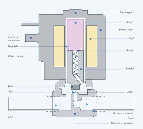
Each of these mounting methods has its own advantages and disadvantages.
Installation of distributors on valves with pneumatic actuator
Benefits
Disadvantages

Installation of distributors in the control cabinet
Benefits of
Disadvantages
The main advantage of air operated valves over solenoid valves is their increased resistance to negative environmental factors and the medium passing through the valve. This is due to the fact that valves with a pneumatic actuator:
How can a system based on a pneumatic valve be more reliable than a system based on solenoid valves? After all, any valve with a pneumatic actuator requires its own distributor, which increases the number of series-connected elements of the system. This should lead to a decrease in the overall reliability of the system. This remark is valid when the valves are operated under ideal conditions.
However, under unfavorable conditions, the safety margin of the solenoid valve may not be sufficient. This follows from the features of its design, described above.
Another factor in favor of pneumatically actuated valves is their lower hydraulic resistance and, as a result, a higher flow rate for the same inlet pressure. This is achieved due to the angled (tilted) design of the valve. The flow passing through it deviates much less from rectilinear motion, therefore, it consumes less energy to overcome the resistance of the valve. As an example, table 1 shows the Kv values for the GEVAX series 19 solenoid valves01R-KBN and valves with pneumatic actuator VALMA series ASV.
| Valve type | Solenoid valve | Air actuated valve |
|---|---|---|
| Fluid Flow Chart | ||
| Valve size | Flow coefficient Kv, l/min | |
| DN 15 | 65 | 70 (+ 8%) |
| DN 20 | 110 | 150 (+ 36%) |
| DN 25 | 180 | 308 (+ 71%) |
| DN 32 | 250 | 608 (+ 143%) |
| DN 40 | 390 | 700 (+ 79%) |
| DN 50 | 575 | 910 (+ 58%) |
Unlike solenoid valves, pneumatically actuated valves are predominantly bi-directional, i.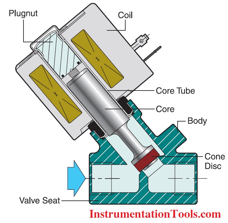 e. they can flow in both the forward and reverse directions (see figure 17). The direction shown in the image on the left is called "inlet under the disk", in the image on the right it is called "inlet above the disk".
It is obvious that when the working medium is supplied "above the disk", its pressure prevents the valve from opening. This effect leads to a decrease in the operating pressure of the valve, but to some extent it can be compensated by an increase in the pilot air pressure.
Example of change in operating pressure with medium supply above and below the disc
Figure 18 shows the nameplate for the VALMA ASV-T-040-AL063 air operated valve.
Figure 18 - Nameplate of the valve with pneumatic actuator VALMA ASV-T-040-AL080-U The operating pressure of the pneumatic valve when the medium is supplied "under the disk" is 6 bar, when the medium is supplied "above the disk" - 5 bar. These data refer to a control air pressure of 6 bar. However, by changing the pilot pressure it is possible to increase the operating pressure of the valve when the medium is supplied "above the disc". This dependence is shown in Figure 19.
It can be seen from the graph that increasing the control pressure to 8 bar allows increasing the pressure of the working medium (at the inlet "above the disk") up to 10 bar, and increasing the control pressure to 9 bar allows increasing the pressure of the working medium to 12 bar.
However, solenoid valves also have advantages over pneumatic valves. Systems based on solenoid valves are generally simpler and cheaper than systems based on pneumatically actuated valves because they consist of fewer components.
Solenoid valves can be used on objects that do not have a pneumatic system. The installation of equipment for air compression and its purification at such facilities leads to a strong increase in the cost and complexity of the system as a whole.
This article describes the design of solenoid valves and seated valves with pneumatic actuator, their advantages and disadvantages are considered. All information provided in this article is based on the design features of both types of valves and may be applicable to valves of these designs, regardless of specific valve models or manufacturers.
Generalized advantages and disadvantages of solenoid valves and air actuated valves are given below.
Solenoid valves
Air actuated valves
Engineer LLC "KIP-Service"
Bykov A. Yu.
Yu.
Locking element of electromechanical action, which performs the function of remote automatic control of the directions of movement of the liquid and gaseous working medium inside the pipeline. With the help of an electromagnetic coil, the required volumes of flow are dosed at a certain point in time.
Widely used in households and large industrial buildings over a wide operating temperature range. In pipelines of housing and communal services, the valve regulates the environment inside the water supply or sewer systems, central heating. It is used on technological lines of chemical and oil refineries, hydraulic filtration pipelines. Let's apply in agriculture: watering designs, dosing and mixing systems.
For the production of solenoid valves, materials are used that meet the requirements of GOST and international standards. The solenoid valve consists of several basic elements:
Body. It can be made of stainless steel, cast iron, corrosion-resistant brass, chemical polymers.
Core induction coil (solenoid). It is located in a sealed case, the winding is made of high-strength technical copper.
Seal. To ensure maximum tightness, the polymer polytetrafluoroethylene (Teflon), heat-resistant rubber, silicone, rubber, and fluoroplastic are used.
Functional elements: plunger, spring, stainless steel stem.
The principle of the solenoid valve is based on the operation of the solenoid coil control element. In the absence of direct or alternating current under the mechanical pressure of the spring, the membrane (piston) of the valve is located in the seat of the device. When an electrical voltage of different power is applied to the solenoid terminals, the core is drawn into the coil, providing the opening or closing of the flow hole. De-energizing the solenoid leads to the closing of the flaps. The design features of the solenoid valve device may vary, depending on its type.
Solenoid valves are divided into several categories.
According to the type of working position, they are distinguished:
According to the principle of operation, electromagnetic valves are divided into:
Valve of indirect action. The impact of the energy of the working environment leads to the opening and closing of the conditional passage.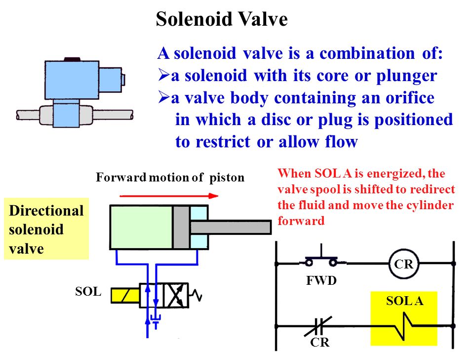 It is controlled remotely, under the action of a pilot valve, which is triggered by the supply of electric current to the coil.
By type of connection to the pipeline:
Coupling. Installation is carried out with the help of an internal pipe thread of a cylindrical shape, with a different nominal diameter and thread pitch. The symbol for the diameter of the solenoid valve is indicated in the product data sheet.
Flanged. Connection to the pipeline by means of paired flanges with holes for bolts and studs. It is applied in pipelines of large diameter. During installation, a sealing ring or a paronite gasket is used.
Type of sealing membrane:
FKM (fluorine rubber) diaphragm.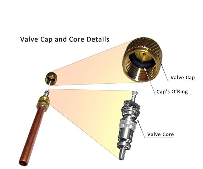 Standard seal, suitable for most non-corrosive media.
NBR membrane. It is used in environments of refined products: gasoline, oils, kerosene, diesel fuel.
EPDM membrane. Characterized by increased resistance to temperatures, works in the environment of chemical solutions and compounds: alkalis, alcohols, glycols, ketones, water, etc.
Any installation work on the valve is carried out in the absence of a working medium in the system and the electrical circuit is de-energized. Before starting work, the pipeline should be cleaned of mechanical particles and suspensions.
How to connect solenoid valve . The solenoid valves in the system are connected in a horizontal position, with the coil up.
For correct operation of the device, the direction of flow of the medium must correspond to the arrow on the housing.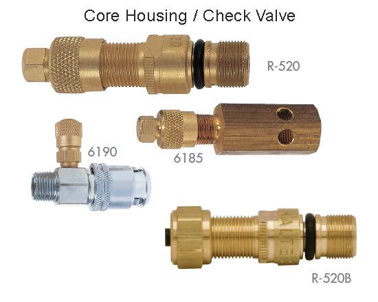
Install the solenoid valve in a location that is accessible for subsequent repair or maintenance.
Do not install the valve in places with high levels of condensation or vibration, areas with possible icing of the pipe, near leaks and gusts.
Installing additional strainers of the correct size will protect the valve from contamination and, consequently, reduce its hydraulic performance.
Reducing the tightness of the product may be caused by the ingress of mechanical particles on the seat of the device. It is recommended to dismantle and clean the device with subsequent installation of a strainer in the system up to the valve.
Failure of the induction coil may be due to incorrect voltage power supplied to the terminals or exceeding the temperature and pressure limits inside the pipeline. The device should be dismantled and the coil replaced.