Systems: Electrical
Commonly Located: The ignition coil is generally located on the upper portion of the frame, near the top of the engine. It can commonly be found above the radiator.
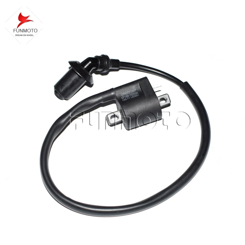
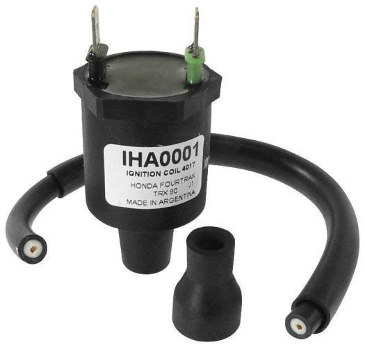
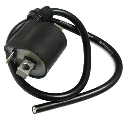
Physical Description: The ignition coil is normally a squarish shape with one to three smaller wires leading into the wiring harness and one larger wire leading to the spark plug. While some ignition coils have a removable spark plug wire, most do not. The wire leading to the spark plug is covered by a thick rubber boot. The spark plug wire boot is usually a separate piece that can be replaced independent of the ignition coil.
Function: When the engine is at top dead center, the pickup coil signals the ignition coil to send a high voltage pulse to the spark plug. The spark plug wire boot ensures that none of this energy escapes on it's way to the spark plug. This high voltage pulse is what causes the spark that ignites the air and fuel mixture in the cylinder.
Maintenance Costs: The ATV ignition coil is a common wear item; therefore, it is not recommended to purchase a used coil as a replacement. Fortunately, the ignition coil is relatively inexpensive.
Filed in: Anatomy of an ATV
Share: Previous article A Look at The BEST ATV Service ManualOriginal price $ 159.99 - Original price $ 159.99
Original price
$ 159.99
$ 159.99 - $ 159.99
Current price $ 159.99
| /
Original price $ 129. 99 - Original price $ 159.99
Original price
$ 129.99 - $ 159.99
$ 129.99 - $ 159.99
Current price $ 129.99
| /
Original price $ 40.00 - Original price $ 40.00
Original price
$ 40.00
$ 40.00 - $ 40.00
Current price $ 40.00
| /
View all ODES UTV Performance mods
ODES UTVS best sellers See more
Original price $ 7.99 - Original price $ 7.99
Original price
$ 7. 99
99
$ 7.99 - $ 7.99
Current price $ 7.99
| /
Original price $ 38.49 - Original price $ 55.99
Original price
$ 38.49 - $ 55.99
$ 38.49 - $ 55.99
Current price $ 38.49
| /
Original price $ 49.99 - Original price $ 52.99
Original price
$ 49.99 - $ 52.99
$ 49.99 - $ 52.99
Current price $ 49.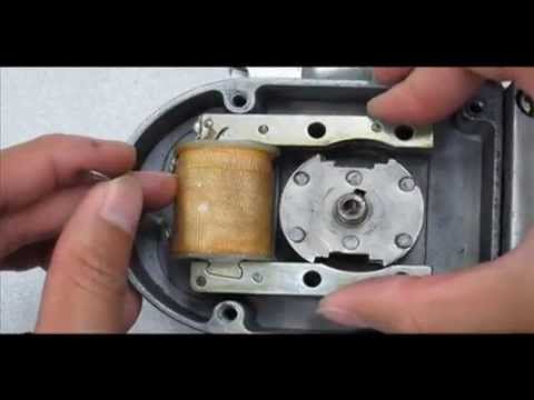 99
99
| /
Original price $ 29.99 - Original price $ 29.99
Original price
$ 29.99
$ 29.99 - $ 29.99
Current price $ 29.99
| /
Original price $ 18.99 - Original price $ 18.99
Original price
$ 18.99
$ 18.99 - $ 18.99
Current price $ 18.99
| /
Sold out
Original price $ 159.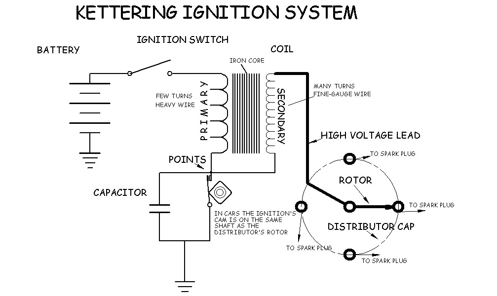 99 - Original price $ 159.99
Original price
$ 159.99
$ 159.99 - $ 159.99
Current price $ 159.99
| /
Original price $ 159.99 - Original price $ 159.99
Original price
$ 159.99
$ 159.99 - $ 159.99
Current price $ 159.99
| /
Sold out
October 8, 2022
Read nowSeptember 16, 2022
Read nowAugust 30, 2022
Read now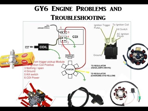 com
comHome - Dirtbike - Dirtbike Features - ATV Electronics series: Part 1 - ignition systems
Few things can be as frustrating as diagnosing electrical systems. After all, there are seldom obvious signs of failure - I mean, you just can't see if electrons are flowing or not. Sure, every now and then you find a corroded connection, frayed wire, or burn looking electrical thingamajig. But how can you tell if your CDI or stator is bad? It's a real drag to have spent $100 or more on a new coil only to find that your safety tether had a bad connection. The key to effectively troubleshooting electrical systems is to have a solid understand of their operation.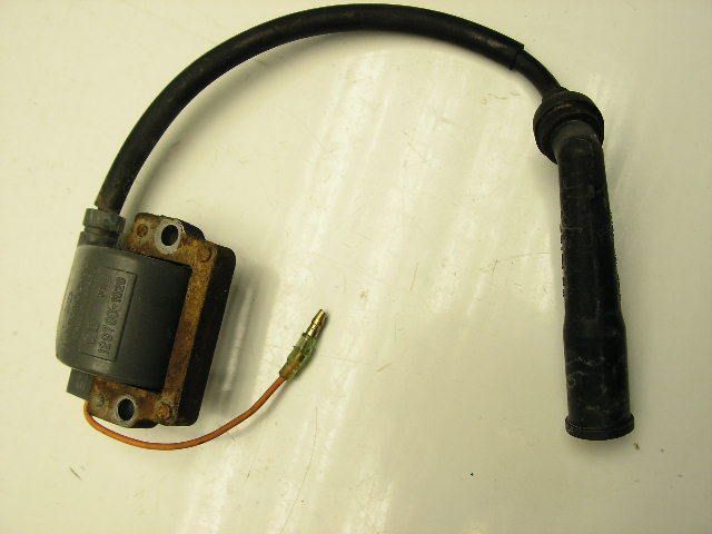 Only then can one efficiently narrow down what the faulty component is. To aid in that process, the technical folks at ORC have decided to put together a three-part "electrical systems" series to cover the three most basic systems of the typical ATV: ignition, charging, and starting. To kick off the series, the first installment handles the most important: ignition.
Of course, the primary purpose of the ignition system is to create a spark. Years ago, a fellow named Kettering came up with a pretty good way to make a spark. Very basically, his invention consisted of two sets of finely wound copper wire - commonly referred to as the ignition "coil" -.that when powered with electricity on one winding would create a sudden jolt, or spark, of electricity on the other when the electrical power is interrupted.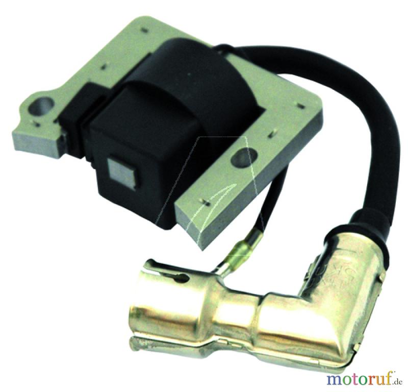 To keep up with a spinning engine, the electrical power is switched on and off via a contact switch that's controlled by a cam lobe driven by the engine. Pretty darn simple, and pretty darn easy to diagnose with basic tools. However, this conventional "breaker" or points-type ignition had reliability issues and was limited to low rpm applications. Enter the age of high tech electronics: integrated circuits, transistorized ignitions, and CDI...
The good news is that CDI, or capacitor discharge ignition, was all that points-type ignitions weren't - they had no moving or wearing parts, could produce a heck of a spark, and could run very high speed. Bad news is that the ignition system now became a "black box", both literally and metaphorically.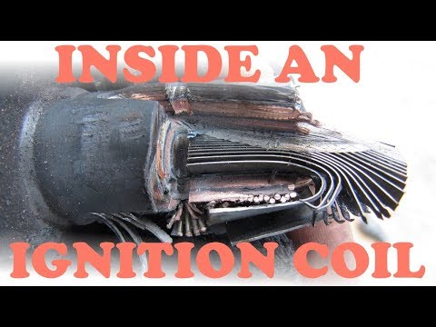 No spark? Might as well start swapping parts until you the spark magically reappears. Not a bad proposition for a dealer that has parts sitting on the shelf he can try with no obligation. But to spend a hundred non-refundable dollars on simply a hunch is a tough pill to swallow.
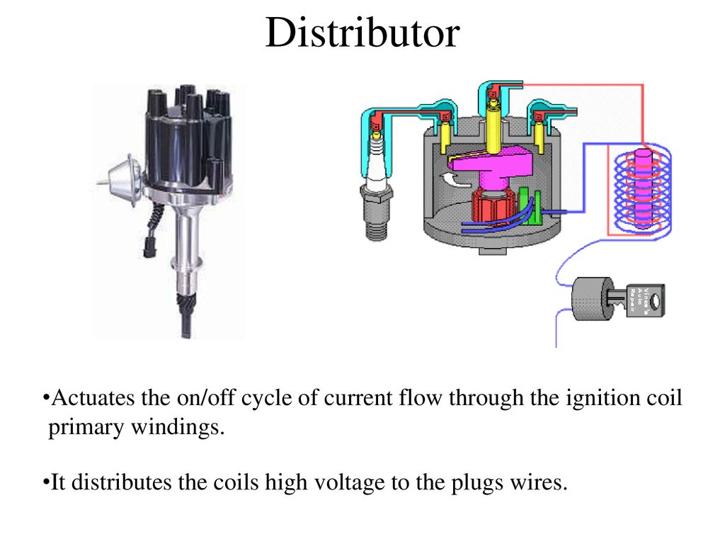
| Schematic of a typical CDI ignition system |
Fortunately, we can break down the operation of the CDI to some basic circuits - the guzzinta's and the guzzouta's (inputs and outputs). Whereas the points-type ignition has only two circuits (power and ground), the CDI has 5 primary circuits. On the guzzinta side we have the obligatory duo of power and ground, but with the added complexity of a circuit to tell the CDI when to fire (trigger circuit), and another to tell if to fire (kill circuit). What's left is the only circuit on the guzzouta side: the power to the ignition coil (fire circuit).
So let's discuss those circuits and their possible failure modes. The CDI's ground (DC negative) is always connected and provides the connection back to the engine's own voltage ground point or reference, which is the same reference the spark plug uses when creating a spark. The key piece of info here is that wherever the CDI makes its ground connection has to be essentially the same ground reference as the spark plug - make sure there's clean metal all the way between the two connection points, and virtually no resistance (ohms).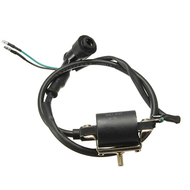 If the CDI makes its ground connection at the frame up near the gas tank, be assured that the circuit from there is good all the way back the cylinder head. Don't rely on a ground connection through engine mounts. They can be intermittent, dirty, corroded, rubber-bushed, or painted. Proper grounding would dictate a ground strap from the engine directly to the wire harness.
Next thing we need is a way to power the CDI. Some CDI's are powered by 12vdc from the machine's electrical system, but most others generate the requisite electrical power from an exciter coil underneath the flywheel. As the magnet on the flywheel passes the exciter coil, electrical current is generated and in the case of a Capacitor Discharge Ignition or CDI, that charge is stored temporarily in a capacitor for a split second until the CDI is told to fire. Since the CDI is already tied to ground, there's only a single wire connecting the exciter coil to the CDI. To check this voltage produced by the exciter is tricky because it requires the engine to be turning. An electric starter can produce the necessary crank rotation, but diagnosis by means of kick starting is difficult since the output voltage varies with engine speed. To check, use a digital voltmeter (DVM) and set to AC scale. Connect one DVM lead to the exciter output wire, and the other to case ground. Most shop manuals will list a minimum AC voltage for both running and starting. Be CAREFUL when testing, the output from the exciter coil can reach 200 volts!
The power stored in the CDI's internal capacitor needs to be put to work, but the key to proper engine performance is doing it at the right time.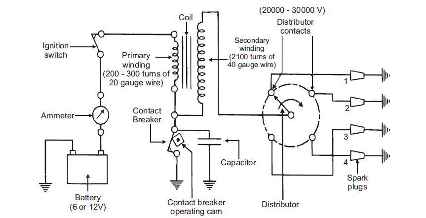 That's where the pulse generator comes into play. Again, underneath the flywheel lies yet another magnet and coil combo, but the sole purpose of these two is to precisely identify to the CDI the position of the crankshaft. That is, it tells the brain box where the piston is and therefore when to fire. Basically, the CDI waits around for the pulse generator to tell it that the piston has just hit some point before TDC, and then waits the appropriate amount of time (dependent on rpm and spark advance) before energizing the guzzouta circuit that sends power to the well-recognized ignition coil. This circuit is diagnosed similarly to the exciter coil above, but instead connect your DVM to the pulse generator output. The voltage is much less and should be listed in your manual.
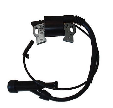
The last CDI circuit is the "kill circuit" which is how the CDI knows to quench the spark and kill the engine. Typically this circuit is switched to ground, and some CDI's require this circuit to be closed, while others require it to be open for engine shutdown. Most safety tethers, kill switches, and ignition switches utilize this circuit to control engine operation. The easiest way to troubleshoot a no-spark malfunction is to pull the spark plug and check for spark by unplugging this circuit. If no spark, then connect a ground wire directly between engine ground and this circuit (on the CDI box side). If still no spark, the problem is likely with another circuit.
To complete the whole ignition system, we still need to produce enough voltage to jump a spark across a 1mm gap, inside a running engine.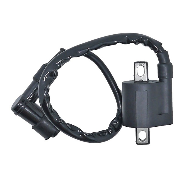 This part of the system hasn't changed much over the years - it's still a good ole ignition coil with a small wire going in, and fat one going out. It's a little different since we no longer have 12vdc going in, but rather nearly 10x that!. It also requires a good ground connection so insure that there's no corrosion, mud, or paint separating the mating connections. Although it's easy to blame coils for electrical problems since it's difficult to test (resistance checks are not always reliable), they are not commonly known to be failure prone. More likely is a bad spark plug cap or connection to the fat plug wire. With some coils passing as much as 60,000 volts make sure your plug wire and cap has no exposed breaks or possible leak paths that water can penetrate.
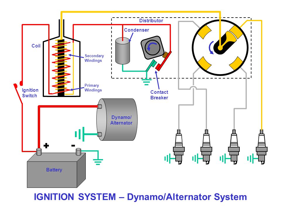 When the coil fires it will seek the path of least resistance, and if there's a way for 60,000 volts to get to ground easier than through a compressed air-fuel mixture (spark plug gap), it'll take it. And water does that job quite nicely.
Stay tuned, next month we'll get into the charging system of an ATV's electrical system.
ATTENTION!!! DO NOT SWITCH ON THE IGNITION WITHOUT THE HIGH WIRE, THE PLUG, OR IF THE PLUG IS NOT TWISTED INTO ITS PLACE OR IS NOT RELIABLELY EARTHED TO THE ENGINE BODY!!!
THE COIL WILL COME WITH A PROBABILITY OF MORE THAN 50 PERCENT!!!
IN THIS COIL, THERE IS A BREAKDOWN INSIDE THE COIL AND THE INTERTURN SHORT CAN APPEAR!!! THE PRESENCE OF THE INTERTURN CLOSURE OFTEN DOES NOT INTERFERE TO WORK AND THE SPARK IS PRESENT, BUT NOT FOR LONG - AT THE END OF THE END THE COIL DIES AT ALL.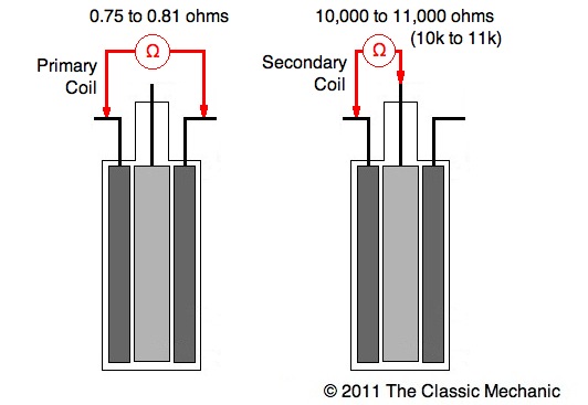
To connect the ignition control unit (BUZ) to the ATV's on-board network (only connector 1 is used), disconnect the standard CDI unit from its connector (on some models, the standard unit is not disconnected, see clarifications in the descriptions) or disconnect the DPK connector, disconnect the BB wire of the standard ignition coil from the spark plug, to the “signal” wire (most often it is a blue or white-blue wire) of the DPK, connect the input of the BUZ (blue wire) ,)
the DPK wire (let's call it "-" DPK) (most often green) is connected to ground (sometimes it is connected to ground only in the CDI unit, sometimes directly in the generator itself, if not, we connect it to the "-" battery, the yellow wire of the BUZ to + Battery after the ignition switch (most often it is a black wire), white wire to the “-” terminal of the ignition coil, Terminal “+” of the ignition coil through a 15 amp fuse to + battery, BB wire to the coil and spark plug.
Everything, you can start. As wound up, you should adjust the speed of the twentieth.
To return to the standard ignition system: disconnect the connector 1 BUZ, the standard CDI unit back into its place, the BB wire from the standard coil to the spark plug.
Connector number 2 is optional, add. functions are activated by shorting the desired wire to MASS !!! If they are not needed, insert a chip into the connector anyway so that WATER does not get in !!! it is necessary !!!
There are a few things to pay attention to when installing and starting up the system. Here is a list of what caused the ignition to work poorly on different quadrics:
 You don’t have to think much about this issue, if the engine starts but it immediately starts to sausage straight from idle - change the wires on the coil in places.
 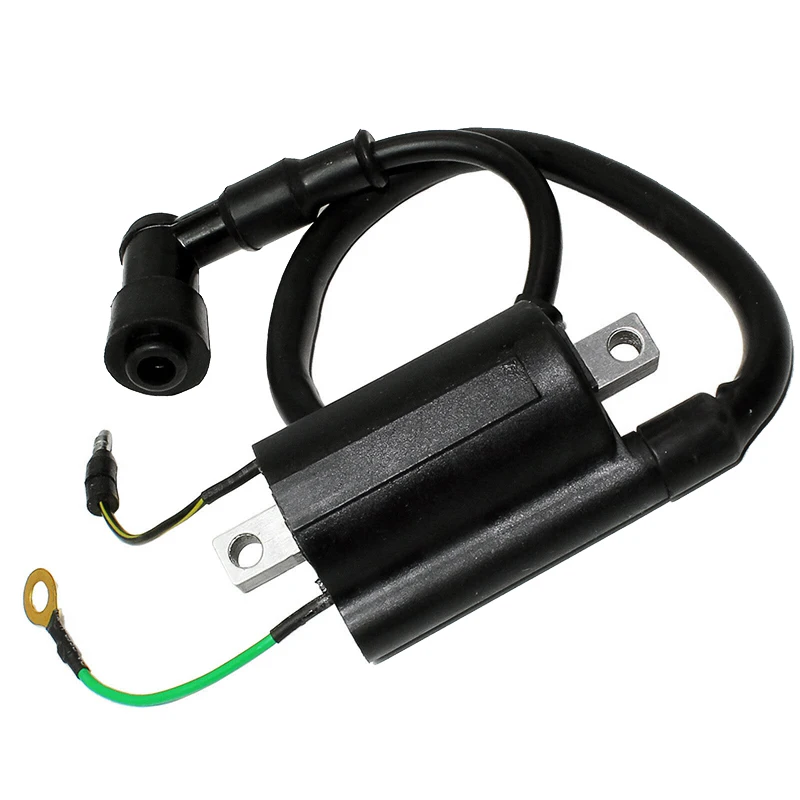 ..)
..) I don't know why this is, but most owners of scooters and motorcycles equipped with a CDI ignition system, if there is a problem with a spark on a candle, they immediately sin on the ignition coil. To all my reasoned arguments in favor of the fact that, in addition to the coil in the electrics of the scooter, there are still a bunch of devices that provide sparking between the electrodes of the spark plug: a generator, an induction generator sensor, a switch, wires in the end - they make glass eyes and repeat their signature phrase as one : "Can't you call her?" You can't, my dears, you can't!
No, of course I can make a smart person and, for solidity, poke a coil in front of you with a tester, as collective farm gurus do. But I won't do that today. For one simple reason: you can “ring out”, measure the resistance of the coil windings, but what will it give us? .. Well, the tester will show us the treasured numbers on the display, so what? And if there is an internal turn-to-turn short circuit in the coil windings, a factory defect, or the winding of one of the coils burned out.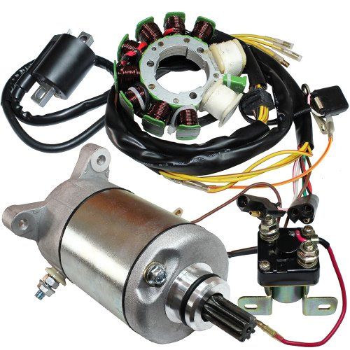 Do you think with the help of a tester you can determine all these malfunctions? I assure you not.
Therefore, since it comes to that and you are inclined to believe that the lack of a spark can still somehow be connected with the ignition coil - we will go from the opposite. Namely: today we will not learn how to check the coil itself, since it is useless and does not give anything, but we will check the electrical parameters of the devices that ensure the operation of the ignition coil. This approach to diagnosing such devices is more effective than the usual “ringing” of the windings for a break or resistance measurement.
The CDI ignition coil is a classic two winding high voltage transformer. The work of which is based on the effect of magnetic inductance.
Inside the ignition coil there is a cylindrical or rectangular core over which a large amount of the thinnest copper wire is wound in a strictly defined order, which is the secondary winding. On top of the secondary winding, a thicker copper wire is wound through the insulation layer, which is the primary winding.
Both windings are connected at their ends to each other and have one common terminal on the body in the form of a ground terminal (green). The second ends of each of the windings have separate outlets on the body in the form of a power terminal and a central contact of a high-voltage wire.
For more clarity, let's break the case and see what's inside.
During engine operation, the alternating current generated by the high-voltage winding of the generator is supplied to the switch in which it is accumulated in a special capacitive storage (capacitor) - this current accumulation principle applies only to AC CDI switches. There are even less common DC CDI switches that use direct current from the battery for storage.
Hence the name of the CDI system, from Capacitor Discharge Ignition - loosely translated, it sounds something like this: “ignition from a capacitor discharge”
the moment of sparking, a special element in the switch (thyristor), which acts as an electronic key.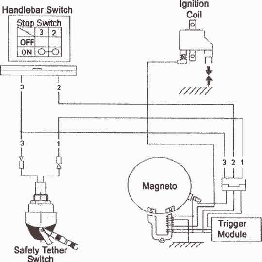 Further, the following happens: the thyristor, under the action of an alternating pulse from the induction sensor of the generator, opens and the current accumulated in the capacitor in the form of a pulse shoots through it to the primary winding of the ignition coil.
When a pulse passes through the primary winding, magnetic induction occurs, under the influence of which an electric current is induced in the secondary winding, many times higher than the current supplied to the primary winding. In fact, in the ignition coil, there is the most transformation of current from a lower (incoming) to a higher (outgoing) current.
The current formed in the secondary winding, through a high-voltage circuit, enters the spark plug and, due to its high voltage, about 18,000 - 20,000V, easily overcomes the air resistance between the electrodes and forms a spark.
Malfunctions as such in the CDI ignition coil are very, very rare, contrary to popular belief. And all of them are mainly associated with damage to the case, burning of the windings, or an internal break, short circuit of the wires.
In all my hard practice, I have only once come across a really faulty coil. And this despite the fact that the owner of the scooter himself ruined it: he forgot to connect the ground to the engine and turned on the starter button ... A very high starting current went straight through the coil to the starter ... And where was he supposed to go? .. There was no mass on the engine. Naturally, the coil could not stand such mockery: it heated up and burst.
To work, we need an ordinary tester with a sound “ringing” function, a 3W control lamp, a piece of thin wire or a carnation, a piece of insulated wire, a screwdriver and, of course, a desire ...
Herself verification is not particularly difficult even for beginners. And it will be connected with measuring the supply voltage supplied to the coil, checking the mass, which must necessarily fit the engine, switch and coil, and checking the integrity of the wires supplying current to the consumers of the ignition system.
Another point: the technique that will be described here can be safely applied not only to a scooter, but also to any other type of vehicle equipped with a CDI ignition system, be it a motorcycle, an ATV, a scooter or even a walk-behind tractor - it doesn’t matter.
Whether the power (impulse) goes from the switch to the coil or not - it directly depends on whether the coil will produce a spark to the candle or not. Power is power, without it, no electrical consumer can work. Therefore, any check should begin with a power check - is it there or not? And only then, depending on the result, finish the check or move on.
We release access to the coil and without removing the terminals from it - we connect the control light to the power wires: green and black and yellow and turn the engine with a starter. In the mode of cranking the engine with a starter, the control light should burn to the floor of the glow.
Coil light on - switch 100% operational.
If your light is off, check the switch and if it is working and there is no voltage at the coil terminals, look for the cause in the wires supplying power to the coil.
The voltage on the switch is checked in the same way as on the coil: touch the green and black-and-yellow wires, turn the engine with a starter and look at the light bulb.
The light on the switch is on, it means it is 100% working.
Another common cause of coil failure when there is power at the coil terminals is poor or no ground. The mass on the coil is checked simply: we put the tester into the sound “ringing” mode, touch any metal part of the engine with one probe, and the green ground terminal with the second.
This spool has good ground.![]()
Malfunctions of the high voltage circuit often leading to a complete or partial (interruption) failure of the ignition system are mainly associated with damage, contamination or breakdown of the spark plug cap housing or breakdown of the insulation of the high voltage wire.
As I said: the current generated by the secondary winding of the ignition coil is very high and it is not uncommon for the current supplied to the spark plug to break its way through cracks in the cap body or a layer of dirt, dust, cracks in the insulation of the high-voltage wire. Which leads to a complete failure of the ignition system. These malfunctions occur very, very often and in most cases lead to a complete or partial (interruption) failure of the ignition system.
In order to check the high-voltage circuit, do the following: We twist the cap from the high-voltage wire; insert a thin nail or piece of wire into it; we bring the nail to the metal case of the engine at a distance of 2-3mm ( This is important! The distance between the end of the wire and the motor housing should be 2-3mm, otherwise screw the switch ) and turn the motor.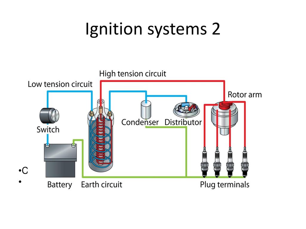
We check the high-voltage wire in a similar way: We unscrew it from the coil and screw in any other piece of insulated instead of it (The wire must be insulated! Otherwise, it will slap so that it won’t seem enough!) wires, bring it to the engine housing at a distance of 2-3mm and turn the engine.
That's actually the whole technique. I've been testing coils this way for a few years now. And for a complete check with almost one hundred percent accuracy, it takes me only a few minutes. Of course, this technique may seem complicated to many of you, but in fact it is not quite so. The main thing is to understand the principle, the rest will follow by itself.