Your ATV’s stator is an important part of the electrical system, along with the battery and regulator. If you have some kind of electrical problem, particularly a failure to charge, the issue is likely with one of these components.
An ATV’s stator recharges the battery while the machine is in use, like an alternator in a car. Your ATV may have a single-phase stator, a three-phase stator, or a bar coiled stator, all of which look differently. Most modern ATVs use a three-phase-stator as these components produce more electricity.
Testing the stator gives you an idea of where to start. If the problem is with the stator, someone can fix it. Here’s how to test your ATV’s stator and fix it if it turns out to be a problem.
Your ATV’s service manual will contain the information you need about your type of stator. It should also illustrate any extra components on your particular model. No matter the type of stator, testing it is a similar process.
Before testing the stator, however, you may wish to take a few additional steps. First, check the battery by placing it on a different charger. Take the time to look for corrosion, and clean the connectors and wiring. If none of those actions fix the battery charging issue, it is time to test the stator.
To test the ATV stator, you will again need the multimeter. You will first perform a static test, or a test done without the engine running and without the stator attached to the ATV. Make sure the ATV is off when you disconnect the stator.
With your multimeter set to ohms, get to work resistance testing each circuit. Connect the multimeter leads to the terminals in the stator’s electrical connector, testing between pins 1 and 2, 2 and 3, and 1 and 3. Compare the multimeter reading to what it should be in your service manual.
The next test is to determine if the stator is shorting out to the ground. For this you will put one meter lead in the connector and the other on the stator body. The correct reading in this situation is OL, or open line. If you see another reading, the stator has a problem. Perform this measurement for each coil/winding/phase.
Another test is the dynamic test, this time with the motor running. This will only work if your battery has some charge. You must set your multimeter to AC voltage for this measurement. You will likely need a friend to help.
With the engine running, measure between coils/pins by connecting the multimeter lead to the terminals in the electrical connector for the stator. Again, measure between 1 and 2, 2 and 3, and 1 and 3. You are looking for a positive reading.
You can also re-do this test with an increased engine RPM. In this case, you are looking for the reading between terminals to increase as the RPM increases. A voltage reading that remains the same from the static test to the dynamic test indicates a problem.
Fixing a stator usually involves unwinding and cleaning the original stator core, then rewinding it with a machine or carefully by hand.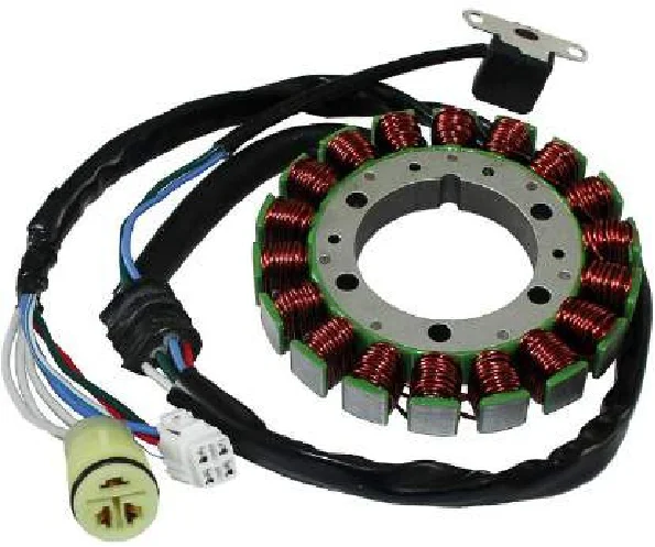 It starts with looking at the coil heads for damaged or burned wires, then cutting out the protective rubber coating from damaged coils. Note which direction the wire wraps around the coil head, then remove terminal clips from the base with a screwdriver.
The next step is to unwind the damaged wire. After this, you will clean the surface of the stator head with fine-grade steel wool. Wipe it clean afterward. The new wire should be the same gauge as the old, wrapped around the heads in the same direction as before. There should be no gaps between the wire wrappings, and terminal leads will require an additional length at the top and bottom.
Crimp the terminal leads to those one-inch lengths using pliers, and attach the leads to the stator with a screwdriver. Then, test the functionality of the repaired stator with your multimeter in ohm setting mode. If all looks good, coat the new wiring with liquid rubber and allow it to set.
If repairing a stator is outside of your skillset or you would rather get a new stator, a full replacement is possible.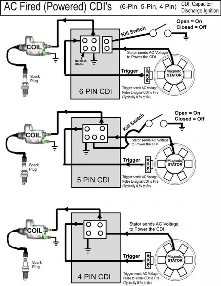 You can either perform the installation yourself or outsource the whole process to a reliable ATV repair expert.
Disclaimer: While we endeavor to keep the information on our blog up to date and correct, Maxtrade (Coolster) makes no representations or warranties of any kind, express or implied about the completeness, accuracy, reliability, suitability, or availability with respect to the website or the information, products, services, or related graphics contained on the website for any purpose. Any reliance you place on such material is therefore strictly at your own risk.
You are experiencing poor vehicle performance and you just know it is your engine again. All other components seem to be checking out and only the stator remains.
The stator is one of the most important components of your motorcycle or ATV. It is one part of your engine that could be a primary culprit and the cause of all your problems.
But how do you test a motorcycle stator?
This article takes you through all you need to know about testing your stator.
A stator is a stationary coil of wires inside the engine case that creates alternating current (AC) voltage which is later converted to direct current (DC) power for use.
Within the stator, a magnet spins and creates AC voltage. AC voltage is then carried out of the case through heavy gauge wires and supplied to the rectifier or regulator at a constant rate.
It is this rectifier/regulator that then converts AC voltage to the Direct Current that powers the whole vehicle.
In motorbikes, the collaboration between stators and rectifiers plays the same role that alternators play in cars.
They regulate the supply of power to the batteries and other components requiring electricity within the bike.
Due to this, when your stator is bad, you’d expect the electrical components within your vehicle to malfunction.![]()
How do you diagnose a bad stator? A multimeter is the only tool you need. It also helps you diagnose other electrical components in your vehicle, so owning one is essential.
To test a stator, you use a multimeter to either run a static test on the resistance of the wires or a dynamic test on the AC voltage reading from the wires. A static test is run while the engine is switched off, while a dynamic test involves procedures while the engine is on.
These two tests have a lot of procedures and peculiarities with them, so we go into full detail next.
P.S: It is important to note that there are either 3 wire stators or 5 wire stators, and the following steps are in the context of 3 wire stators.
The static test is one you undergo with the engine switched off and remains the only option if your engine or vehicle fails to start.
With the static test, you measure the resistance within all the wire phases coming out of your stator.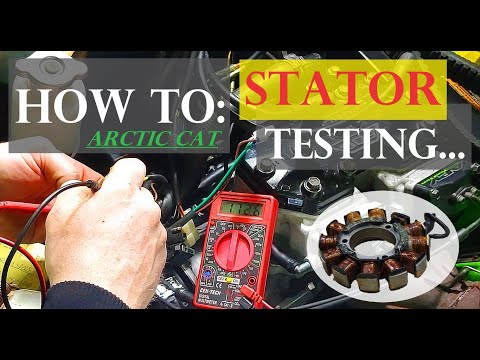 You collectively measure each phase against each other, and also individually measure each phase against a grounded surface.
Let’s name each phase; P1, P2, and P3. Here are the steps to follow.
Note that the expected ohm reading from this test differs based on the stator model, and not all multimeters are sufficiently featured for this.
The following steps prove to be universal tests you can carry out with every type of multimeter.
You can check each wire individually against a grounded metal surface close by. To do this, you
The dynamic stator test is carried out when the vehicle is switched on. What is generally measured here is the voltage produced by the stator through each phase.
Note that different stator models have different recommendations for AC voltage readings, so you want to check your manual before proceeding.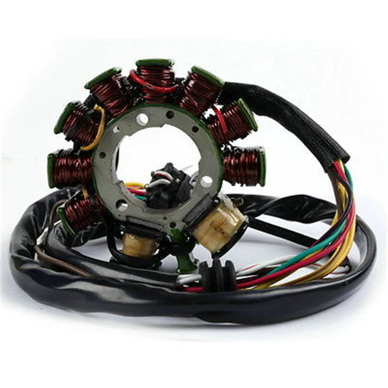
To run a dynamic rest on your stator, you
This procedure is repeated with the probes interchanged between P1, P2, and P3. If the whole procedures seem tricky, here is a video that shows how to run comprehensive static and dynamic tests and what to expect.
Some symptoms of a bad stator include no spark or weak spark supplied to the spark plug, or engine misfiring.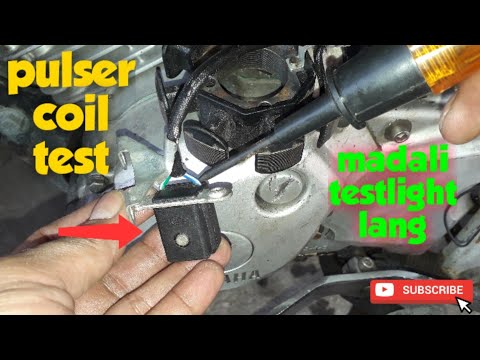 You also experience poor performance when you increase RPM and engine backfiring.
A good stator is expected to have between 0.2 to 0.5 ohms. This value depends on the model of the stator, so you want to check the manual before coming to a conclusion.
To test if a stator is working, you either run static or dynamic tests through the wires. Here, you check for continuity and appropriate voltage readings when the engine is revved up.
A good stator is expected to produce a reading above 60 VAC when revved up to 3000 RPM. This value differs based on the stator model, so you have to check your manual to conclude.
To check AC voltage on a stator, you turn your meter dial to VAC and use the probes to measure the output from each stator wire when the engine is revved up.
 12.2021Company informationComments: 0
 The generator is one of the main mechanisms of any ATV. During the operation of the ATV, it creates an electric current from the rotation of the crankshaft. During the operation of equipment, it is constantly in operation, so after long-term use there is a possibility of its breakdown.
All ATVs presented on the page https://sh.sh3011.ru/kvadrocikly/cforce-600-eps.html are powered by internal combustion engines. With the help of a powerful motor, the necessary cross-country ability and speed are provided. While the engine is running, the generator continuously generates electricity, which is used to power various electrical appliances and the ATV. nine0003
ATV alternator breakdowns are not uncommon, due to the constant operation of this unit. If there are problems with its functioning, there is usually a serious disruption in power generation. If this happens, then you can independently check the main elements of the entire system. To carry out verification work, you can use a conventional multimeter. Everything must be done in the following sequence:
ATV alternator repair procedure involves replacing it because this unit is rarely repaired.
Repairing an ATV alternator is a complex process, so ATV owners most often just replace it with a new unit.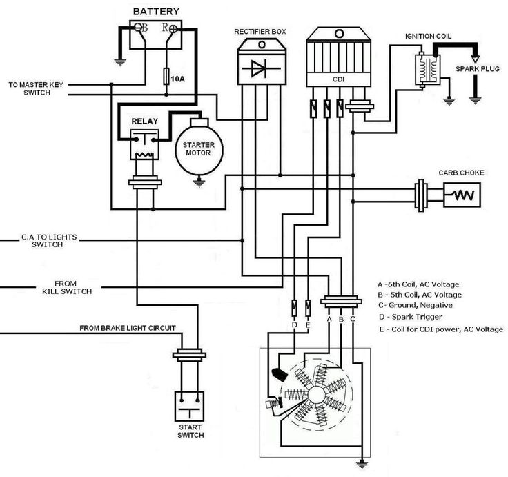 The disassembly process includes the following steps:
This completes the dismantling work. Installation of a new unit is carried out using the same tools, only in reverse order. When installing the right engine cover, a new gasket must be installed. If it is not there, then it is best to coat the surfaces to be joined with sealant to prevent moisture from penetrating into the mechanism. On the site https://sh.sh3011.ru/ you can learn more about the features of repairing ATVs and checking the operation of the main components and assemblies. nine0003
Just like that, without a minimum knowledge of electronics, at least at the level of the school curriculum (like mine) and the simplest multimeter tester - you won’t be able to check the generator, don’t even dream. Before undertaking such work, you should at least be able to use a tester and understand that the current can be AC or DC, know what an electrical impulse is and what resistance is. Do you know all this? Did you have a tester in your hands? If so, then let's not delay. nine0003
Checking the generator's performance - you should start with measuring the voltage that the generator should actually generate and transmit via wires to consumers. We look where the wiring harness from the generator comes out of the engine - we move along it until we reach the connector with which the generator is connected to the on-board network of the scooter.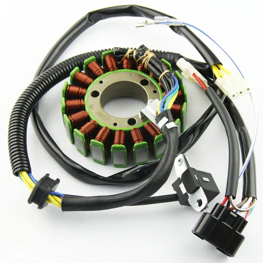
On the vast majority of scooters, the alternator connector looks something like the picture. In the common connector, there is one plug and two wires that are connected to the scooter's on-board network through round terminals. nine0003
The plug combines the connectors of the two main windings of the generator: The working winding (yellow wire), which ensures the operation of the headlights, turn signals, lights and other consumers. And the control winding (white wire), the control winding provides voltage control in the main winding of the generator. That is, when the voltage in the working winding of the generator rises above the specified limits, the voltage regulator relay supplies current to the control winding of the generator, due to which the voltage in the working winding of the generator drops to a predetermined limit. When the voltage drops, the reverse process occurs. nine0003
In this generator, the main windings are wound with thick copper wire on six coils.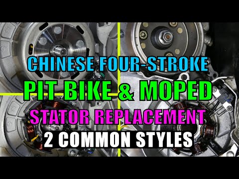
The third winding of the generator, which is commonly called high-voltage or induction and magnetic induction sensor of the generator, is connected to the scooter's on-board network through round terminals.
High-voltage winding of the generator - provides the generation of high alternating voltage (the voltage in this winding can reach 160 V or more), which directly enters the switch where it is rectified, then accumulates in the capacitor and at a certain moment is supplied to the ignition coil in the form of a pulse. nine0003
In this generator, the high voltage winding is wound with thin copper wire on two coils. The coils of the high-voltage winding are carefully insulated on the outside.
There are generators in which the high-voltage winding is wound on only one coil.
A small clarification: ignition systems in which a DC CDI type switch is installed, the high-voltage winding does not participate in the formation of a spark charge on the spark plug, so there is no point in checking it. Scooter manufacturers install a generator with a high voltage winding, but do not use it (meaning ignition systems with a DC CDI switch). It is simply wound on the generator and that's it. I will say more: due to the fact that the winding is not loaded with anything during the operation of the generator, over time it simply burns out. nine0003
An example of a generator, on two coils of which a high-voltage winding is wound in no way involved in operation. I checked this winding - the tester showed an open circuit, which confirms the above.
The resistance of the supply winding of the generator is always greater than that of the other windings. The wire coming from the inducing winding of the generator is almost always red-black.
Magnetic induction sensor, when a special ledge on the generator rotor passes by, generates a sign-alternating pulse that opens a thermistor through which the switch capacitor is discharged to the ignition coil. nine0003
The sensor itself
The ledge on the generator rotor
The wire coming from the magnetic induction sensor almost always has a white-blue color.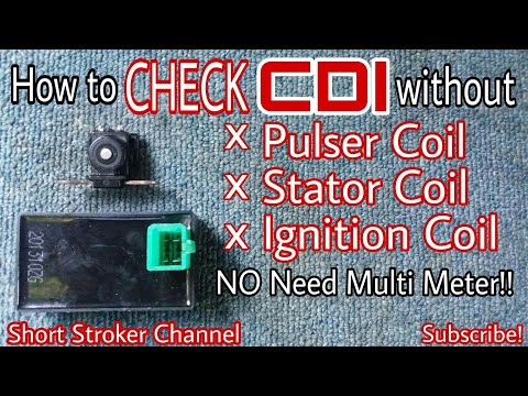
A small educational program: Merchants and collective farm tusks, magnetic induction generator sensor, CDI ignition systems - called the Hall sensor. My relatives ... Maybe that's enough already? .. Where does this illiteracy come from? .. The magnetic induction sensor of the generator, the CDI ignition system, namely, this system is discussed in this article - has nothing to do with the hall sensor! And do not listen to these traders and "gurus" who claim otherwise...
The test itself
Switch the tester to the AC measurement mode (ACV) on the range of 200 V and no less. Remember that the voltage of the inducing winding can reach 160 V or more, so the measuring range of the voltage of the inducing winding must be at least 200 V.
red wire) of the leading winding of the generator. We turn on the ignition, and turn the engine with a starter. A fully serviceable inducing winding should give approximately the following values. nine0003
The pulse generated by the sensor is very weak, so we switch the tester to the ACV measurement mode on the 2 V range.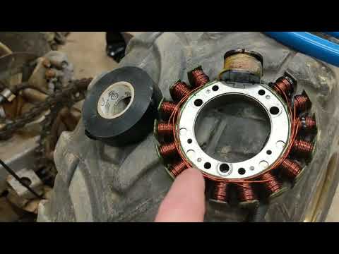 Measuring the pulse from the sensor in a higher range may not give a result, since the tester may simply not catch it. For this purpose, use only a tester with a range in the AC voltage measurement mode of not more than 2 V.
We do everything exactly the same as in the first example. The pulse from the sensor should give approximately the same values. nine0003
By analogy with the first two examples, we measure the voltage in the working winding and the control winding. We put the tester in the mode of measuring alternating voltage (ACV) in the range of 200 V and carry out the measurement.
Well, what did you measure? .. Do all windings generate current? Or not all? .. If any winding does not produce current, then if you want it or not, you will have to remove the generator and check it in more detail. But if the windings generate a current of about the same magnitude as in the pictures, then this means that your generator is in perfect order.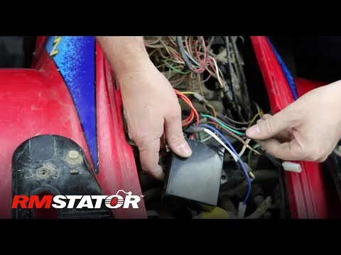 Something like this…
In-depth check
We lay the generator so that the generator winding leads are accessible to you. We determine the ends of the conclusions of all the windings of the generator. Finding the ends of the windings is very simple: we look at the color of the wire that is soldered to the terminal block and determine what kind of winding it is.
I marked the ends of the windings with arrows. I selected the arrows by color in accordance with the color of the wires soldered to the terminal block. The green arrow marks the terminal block on which the ends of all windings are soldered - this is the ground terminal block. nine0003
We switch the tester to the continuity mode, take any wire from the common harness, connect any tester probe to this wire, touch the terminal block to which this wire is soldered with the second probe. The tester should beep and show zero resistance.
If the tester is “silent”, shows numbers instead of zeros, then this means that somewhere there is a wire break or poor contact between the end terminal and the wire.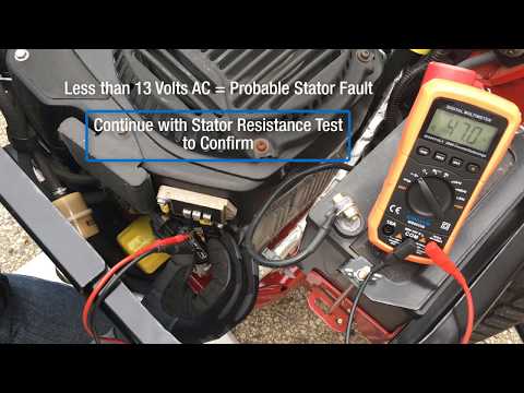 Inspect the wire carefully for a break and, if necessary, replace it with a new one. The remaining wires, including the sensor wire, are checked exactly according to the same principle. nine0003
After checking the wires, we proceed to check the generator windings for open circuit and interturn circuit. We switch the tester to the continuity mode, touch the generator case with any probe of the tester, touch the end of the wire of any winding or terminal block with the second probe.
The high-voltage winding in continuity mode should show approximately this resistance value. If the high-voltage winding did not show resistance or showed but little resistance, then this means that somewhere there is an internal open circuit or an interturn short circuit. You understand that such a malfunction is not “treated”. nine0003
When checking the remaining windings, the tester should emit a beep, the resistance of the working windings is very small, so most likely you will see only zeros on the tester display.