Delivery options and delivery speeds may vary for different locations
Sign In
or enter a zip code
Email * Password *
REPAIR & HOW TO
MAINTENANCE
TROUBLESHOOTING
GUIDES
TIPS & TRICKS
ALL ARTICLES WATCH VIDEOS ABOUT US SHOP PARTS CONTACT US
The electrical system on a motorcycle, ATV or side-by-side is made up of three components: the battery, the stator and the regulator/rectifier.
If the electrical system on your vehicle isn't charging, the problem is likely one of those three components. The only way to be sure which component in the electrical system is at fault is to test all three. Watch the video above or read on below to see how to test a regulator/rectifier.
To test a regulator/rectifier, you'll need a digital multimeter with diode testing capabilities. If you don't already own a multimeter, now is a good time to get one.
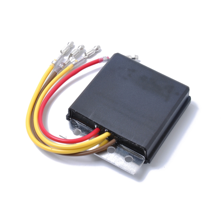
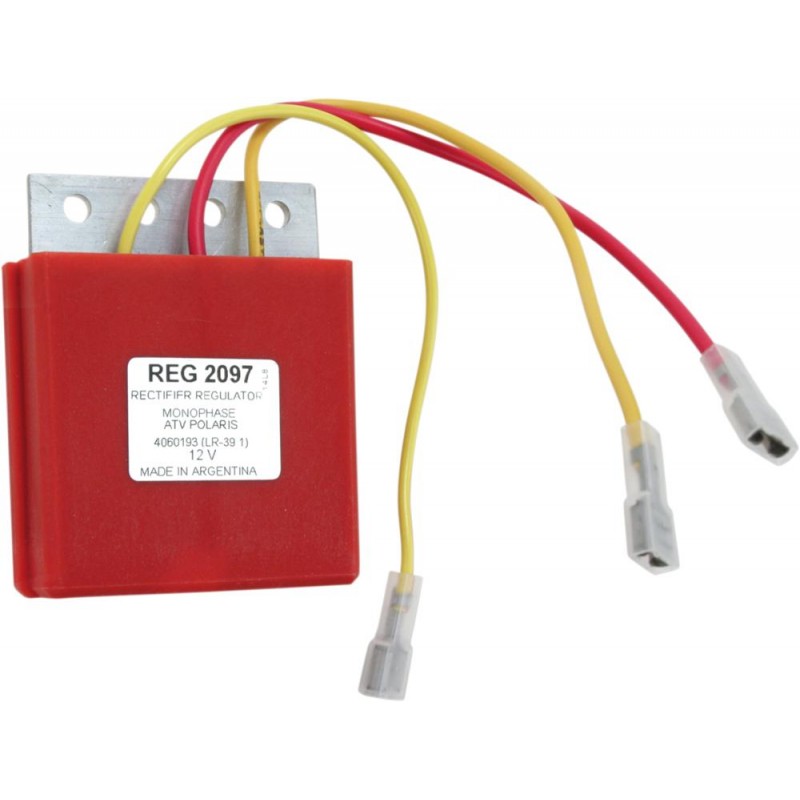
What is a Regulator Rectifier?A regulator/rectifier is an electronic unit that takes the AC electrical current generated by the stator, converts that current into DC electrical current, and sends the DC current to the battery. The rectifier portion of the regulator/rectifier unit is responsible for converting the current from AC to DC, while the regulator portion is responsible for controlling the amount of current sent to the battery so that it doesn't damage it.
A regulator/rectifier contains a set of diodes. A diode allows an electrical current to flow through it in one direction, while blocking the electrical current from flowing through it in the other direction.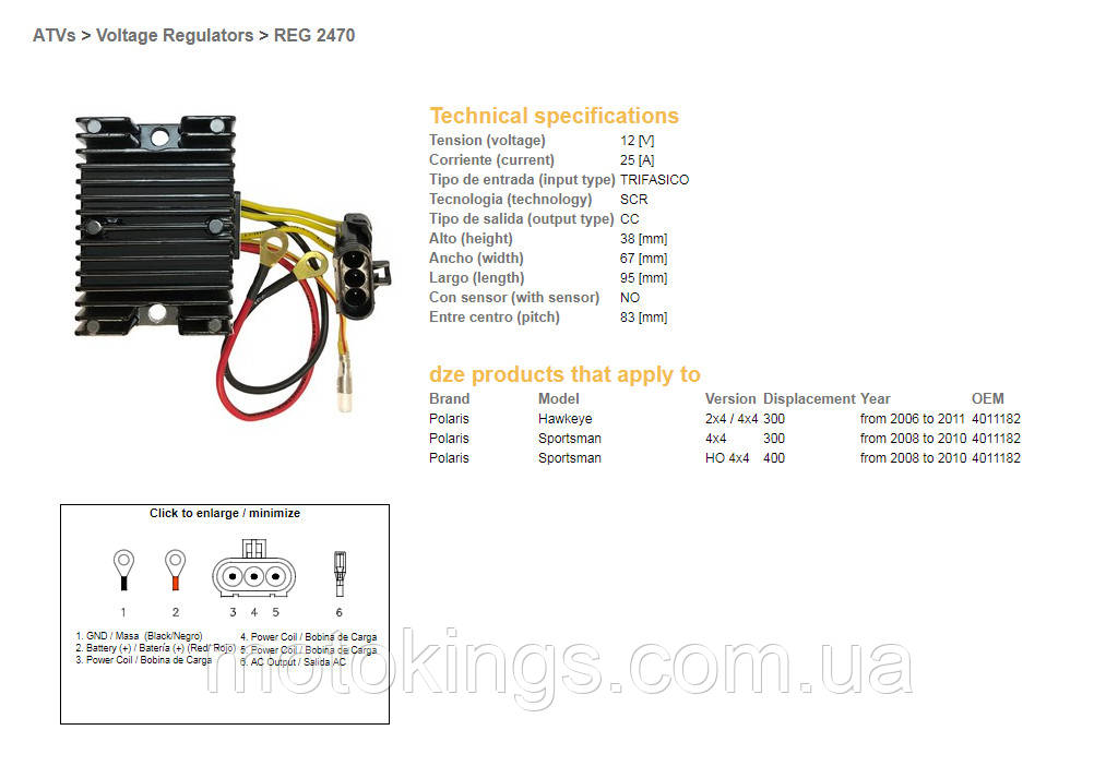 The flow of electrical current through a diode is known as bias, with the allowed direction of current flow called forward bias, and the blocked direction of current flow called reverse bias.
To determine that a regulator/rectifier is working properly, it's necessary to test each of its diodes to see whether they are forward biasing (allowing current flow) and reverse biasing (preventing current flow) correctly. Regulator/rectifier units vary from model to model, and manufacturer to manufacturer. Some regulator/rectifiers are easier to test than others, and some can't be tested at all.
There are two electrical connectors on a regulator/rectifier. These are usually a gray three-terminal connector that receives current in from the stator; and a black two-terminal connector that sends current out to the battery. The inner terminal on the black two-terminal connector is the positive terminal, and the outer terminal is the negative terminal. Some regulator/rectifiers have a black three-terminal connector, with the center terminal being a ground.
NOTE: When testing a regulator/rectifier, set your multimeter to the diode setting.
Regulator Rectifier Test #1: Forward Bias of Positive Circuit DiodesPut the multimeter's negative lead on the positive terminal of the black two-terminal connector. Next, put the multimeter's positive lead on all three terminals of the gray three-terminal connector individually.
The multimeter should give a positive reading in volts, which indicates that each diode is allowing electrical current to travel through (forward bias), and is therefore functioning correctly.
Regulator Rectifier Test #2: Reverse Bias of Positive Circuit DiodesPut the multimeter's positive lead on the positive terminal of the black two-terminal connector. Next, put the multimeter's negative lead on all three terminals of the gray three-terminal connector individually.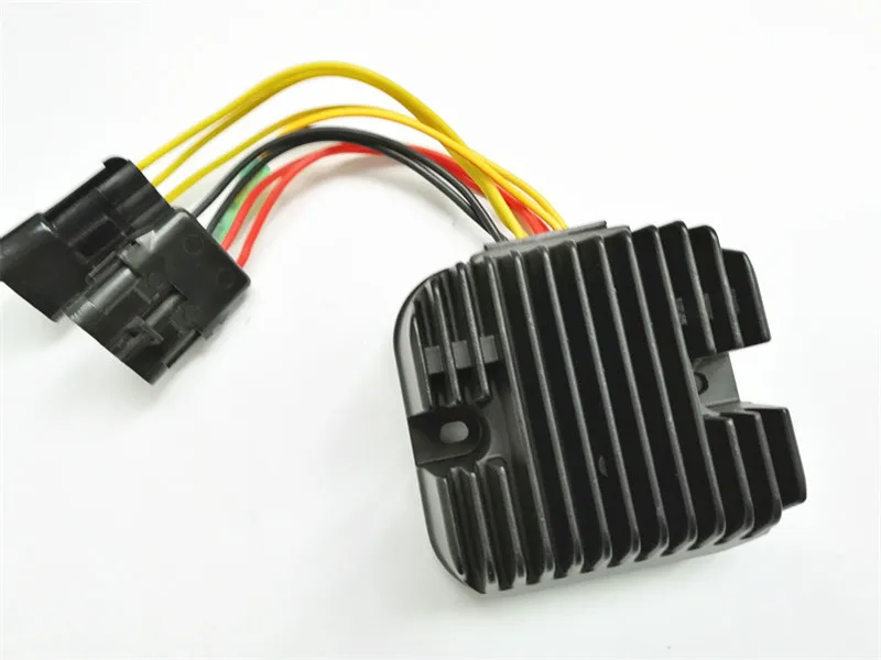
The multimeter should give a reading of "OL", which indicates that each circuit is open (OL stands for open loop) and the diode is preventing electrical current from travelling back through (reverse bias), and is therefore functioning correctly.
Regulator Rectifier Test #3: Forward Bias of Negative Circuit DiodesPut the multimeter's positive lead on the negative terminal of the black two-terminal connector. Next, put the multimeter's negative lead on all three terminals of the gray three-terminal connector individually.
The multimeter should give a positive reading in volts, which indicates that each diode is allowing electrical current to travel through. If any of the forward bias test readings fail to show forward bias, or if any of the reverse bias test readings show a voltage, the diode has failed and the regulator-rectifier unit must be replaced.
Regulator Rectifier Test #4: Reverse Bias of Negative Circuit DiodesPut the multimeter's negative lead on the negative terminal of the black two-terminal connector.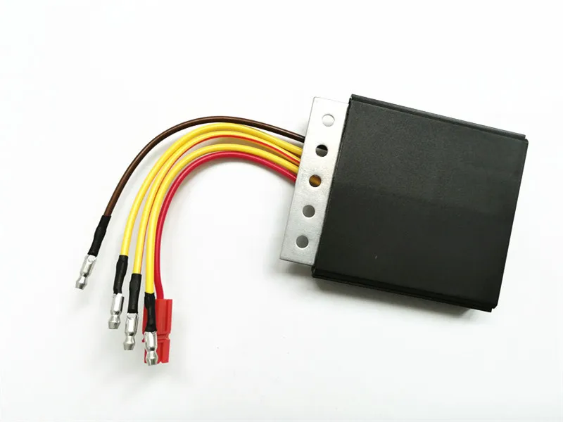 Next, put the multimeter's positive lead on all three terminals of the gray three-terminal connector individually.
The multimeter should give a reading of "OL", which indicates that each circuit is open, and the diode is preventing electrical current from travelling back through.
Testing Regulator Rectifiers by ManufacturerHonda Regulator Rectifier TestThe forward bias measurement for the positive terminal diodes and the negative terminal diodes in the Honda regulator-rectifier should be about 0.48 volts to 0.52 volts.
Watch the clip below to see the Honda regulator-rectifier test in action.
The forward bias measurement for the negative terminal diodes in the Yamaha regulator-rectifier should be about 0. 48 volts to 0.52 volts, and the positive terminal diodes should be about 0.12 volts.
The reason for the change in readings between the positive and negative circuit diodes is that there's additional circuitry within the Yamaha regulator rectifier that affects the readings.
Watch the clip below to see the Yamaha regulator-rectifier test in action
Polaris Regulator Rectifier TestThe forward bias measurement for the negative terminal diodes in the Polaris regulator-rectifier should be about 0.48 volts to 0.52 volts. However, the reading from the negative terminal diodes will show OL.
The reason for the change in readings between the diodes is the additional circuitry within the regulator rectifier affecting the readings.
Watch the clip below to see the Polaris regulator-rectifier test in action.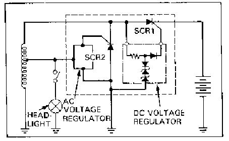
Although you can test some or all of the diodes on most regulator/rectifiers, on others the circuitry on the regulator side of the unit prevent you from testing both the positive and negative sides of the rectifier's circuit. If your vehicle's electrical system isn't charging properly, and the regulator rectifier is one that can't be completely tested with a multimeter, use a process of elimination to determine which of the three main components is at fault.
Watch the video below for more on how to test an ATV stator, rectifier and battery.
Test that the stator is generating power and test the wiring for shorts. If all those tests check out, then the regulator rectifier has to be the problem.
Watch the video below for more on how to test a stator on a motorcycle. ATV or UTV.
body
So your ATV battery won’t charge, not from running the bike and not even when using an external battery charger. Or maybe it seems to be charging just fine, but you can’t get it actually to hold a charge?
There are a few things you should look into before spending money on a new battery or other parts. If you’re lucky, you can fix the issue without even spending one single dollar.
Before you begin troubleshooting, it may be a good idea to read this post on how an ATV charges its battery.
Today’s post will cover these three different scenarios:
Let’s dive into the actual troubleshooting.
Page Contents
It’s a good idea to start your troubleshooting by identifying whether your ATV has a faulty charging system or if the problem is with the battery itself.
The easiest way to do this is by trying to charge the battery with an external battery charger.
If the battery charges fine when using a charger and holds its charge when sitting a few days under no load, you know that the problem is with the ATV and not the battery.
If it does not charge or hold a charge when sitting disconnected, well, then you know that the problem is with the battery.
This battery has gone bad and cannot be charged to hold more than 4.25 volts.Even if your battery is brand new and you are experiencing issues, I suggest you follow these steps. Brand new batteries may be damaged as well.
I generally recommend using a good quality fully automatic battery tender (or a so-called smart charger) to keep your ATV battery in good shape when the bike is not in use or whenever it needs need to be topped off.
Smart chargers come with the advantage that they will automatically shut off when the battery is full or if there is a short or another issue inside the battery.
My trusty Ctek Multi XS 3600 is a cheap charger/tender that does its job well.I’ve been using Ctec chargers with great success for many years. The Ctec XS 0.8 is a reasonably priced, high-quality charger that fits well for most ATV batteries. Click here to see today’s price over at Amazon.
 On some ATVs, it may even be at the rear of the bike.
Related:
When the charging cycle is complete, it’s time to read what voltage the battery holds. To do this, you will need a basic multimeter.
If you don’t have one, you can get them cheap at your local auto parts store. Even the cheapest ones will do the job. Every home mechanic should have one, and I promise that you will find plenty of uses for it as soon as you learn the basics of how to use it.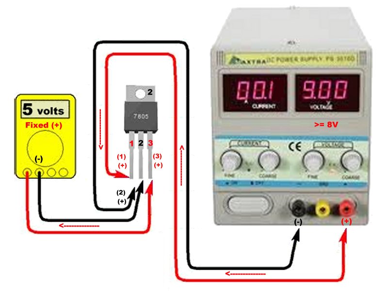
Now you should know whether you have an issue with the battery or if the issue is with the bike’s charging system.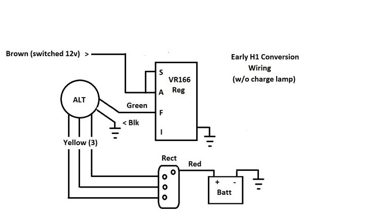
Here are the most common causes when the battery won’t charge, even when using an external battery charger:
No battery lasts forever, and at some point, all batteries will stop working. If you take proper care of the battery, it should last for many years, but you can ruin it in months or even days if you misuse it.
If you could not charge the battery above 12.4V, there is a good chance the battery has gone bad from misuse or just from being old.
There may be a bad cell with an internal short that prevents the battery from taking a proper charge.
Another (and better) way of testing if the battery has gone bad is performing a so-called “Load test.” This simple test measures what charge the battery can maintain even under heavy load. You’ll find instructions on how to perform this test in this post about what to do when a battery keeps draining for no apparent reason.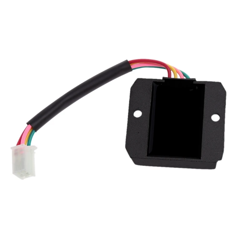
Acid lead batteries need a certain fluid level to take and hold a charge. The electrolytes should fully cover the plates inside of the battery.
If your battery is the Lead-Acid type and has covers that are meant to be opened, you can follow these simple steps to inspect and top of a battery that is low on battery acid.
Warning 1: Do not try to open a battery that is not designed to be opened. If fluid levels run low on a battery like this, there is nothing you can do but replace it with a new one.
Warning 2: Battery acid is highly corrosive and will cause permanent damage if it gets in contact with your skin or eyes. Use proper eye protection and rubber gloves.

In this scenario, the battery will charge just fine when you hook up an external charger, but it will not charge from running the ATV.
There are a few common causes you need to address.
The charging system on an ATV is quite simple but nowhere near as efficient as the one you will find on a car. It uses a stator that produces a current inside of the engine when the engine is running. The output power from a stator is much less than what you get with an alternator used on cars.
The current then runs through a voltage regulator/rectifier that converts the current from three-phase AC voltage to DC voltage and regulates the output current to 14V – 14.5V. This current is then what’s charging the battery and powering all of the bike’s electric components.
The stator and rotor are located inside the engine behind this cover.Even when the system works as intended, it may sometimes struggle to keep up to charge the battery to a full charge. This happens when you combine a low output charging system like the one you find on ATVs using power-hungry accessories like a winch or heated grips.
You can test the stator using a multimeter to measure resistance; this post describes the steps.
Alternatively, you can measure what voltage output you get from the stator. This method is less accurate but will give you a good indication of whether the stator is working correctly or not.
The output voltage on a working ATV stator should be about 20V AC at idle to 40V AC or more when revving.
If any of the three phases did not put out 20V – 40V or more, the stator is likely not working correctly and needs to be replaced.
If the stator checks out fine when doing the tests above, it’s time to see if the voltage regulator works as it should.
 5V. This is also not good and usually means that the regulator has gone bad and needs to be replaced.
ATVs are often used in wet conditions or bumpy off-road riding. This leaves the wiring particularly exposed to corrosion or coming loose.
A corroded or loose connection will prevent the battery from being properly charged.
Disconnect the battery connectors and clean them with some sandpaper before installing them again. The ground wire is particularly prone to corrosion.
Do the same with any exposed connectors found in the wiring connecting the stator and the battery.
In this final scenario, we will cover what may be wrong when the battery seems to be charging just fine but then loses its charge after just a day or two, even when disconnected from the bike.
If you suspect that something other than the battery itself is causing it to drain, please refer to this post for proper troubleshooting for a battery that keeps going dead.
Even if the battery seems to be charging fine, there is a chance that fluid levels are low. Make sure all levels are correct as described above and recharge the battery to see if that helped.
Sulfation is a naturally occurring chemical reaction happening inside the battery when it’s being discharged. The process normally gets reversed when the battery is charged again.
Under certain circumstances, the sulfation becomes permanent and has damaged the battery.
This may happen when:
A sulfated battery loses a lot of its capacity and behaves as a small battery would. When you try to charge it, the charger will indicate that it is fully charged after just a short time of charging. But as soon as you disconnect the charger, the voltage will drop in just a matter of hours.
In some cases, it is possible to salvage a sulfated battery. But in most cases, the damage is beyond repair, and the battery needs replacing.
Try slow charging (trickle charging) the battery using a low amp charger 24h or more. Sometimes, this may bring a dead battery back to life.
There are also chemical treatments available that may help you recondition a sulfated battery. But because ATV batteries are relatively cheap, I recommend that you rather get a new battery instead of spending time and money on a battery repair that may or may not be successful.
Regulator-Charging Relay for Motorcycles Honda, Yamaha, Suzuki, Kawasaki, Ducati, KTM, Harley Davidson.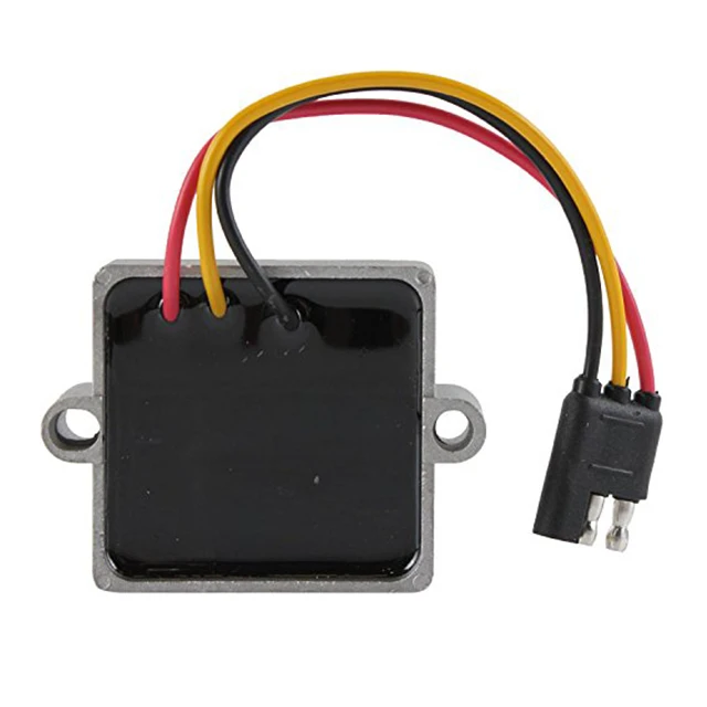
Sort by: name price popularity
Page: 1 | 2 | Show all
Add to compare
Charging relay BMW F650CS, F650GS 99-11, G650X, F800S, F800ST 07-11
Charging relay for motorcycle BMW F650CS, F650GS 99-11, G650X, F8001S nine0004
Add to Compare
Special Hit
Charging Relay Honda CBR1000RR, CB1000R SC60 08-13, CBR600rr CB600 Hornet PC41 07-12, DN-01 (NSA700A) 08-09, NC70.
Motorcycle Charging Relay for Honda CBR1000RR, CB1000R SC60 08-13, CBR600rr CB600 Hornet PC41 07-12, DN-01 (NSA700A) 08-09, NC700X 2012-., sh400.
Add to compare
DiscountHit
Charging Relay Honda CBR250, CB-1, CB400SF, CB400Vtec, CBR400, CBR600, CBR900, VFR750, CBR1100xx
, VFR750, PC800, XL1000, VTR1000f, CBR1100xx.
Add to Compare
Charging Relay for Honda NV400 Steed, VF750C MAGNA, VT600C, Ch350
Charging Relay for Honda Motorcycle NV400 Steed, VF750C MAGNA, VT600C, Ch350
Add to Compare
Charging Relay for Honda VFR750F, VFR800, VTR250, VT250, CBR600F, NT650, VFR400, VF750C.
Charging relay for Honda VFR750F, VFR800 98-01, VTR250, VT250, CBR600F, NT650, VFR400, VF750C.
Add to comparison
Discount
charging relay Honda XL100, XL125, XL150, XL185, XL200, XL500, XL600
charging relay for Honda XL100, XL125, XL150, XL185, XL200, XL600, XL600, XL600 MTX250. nine0-07.
Charging relay for Kawasaki motorcycle ZZR400-1, ZZR400-2, ZZR600, ZXR250, ZRX400 1990-2007.
GS500 89-09, RG500 86-87, DR650 90-91Charging relay for Suzuki AN125-AN150 Burgman 1995-2000, UE125-UE150 2001-2011, GSX250 1991-1997, RG880 Bandit91-1993, GSXR400 1987-1994, RF400, GS500 1989-2009, RG500 1986-1987, DR650 1990-1991.
Page: 1 | 2 | Show all
Some theory of the charging system.
When we start the motorcycle, the generator starts to work, namely to generate current.
From the generator, the current goes to the relay-voltage regulator, and from the relay-regulator to charge the battery and power the motorcycle's on-board network.
The alternator produces alternating current and at the same time the voltage varies depending on the engine speed, from about 50 to 90 volts, AC, and the operating voltage of the motorcycle is 12 - 15 volts, DC.
In order to convert alternating current to direct current and maintain a given voltage in the region of 12 - 15 volts, a voltage regulator relay is needed, the failure of which can be legends.
However, it is not always the voltage regulator itself that is the cause of failure of the motorcycle charging system.
General scheme of work.
Voltage regulator test. nine0004
Things are a little easier here.
• Connect the tester to the battery in DC current measurement mode.
• Start the engine.
• Turn on high beam headlights.
• Set engine speed to 5000 rpm and hold in this position.
• We look at the tester readings.
• With a good charging system, the voltage should be between 13.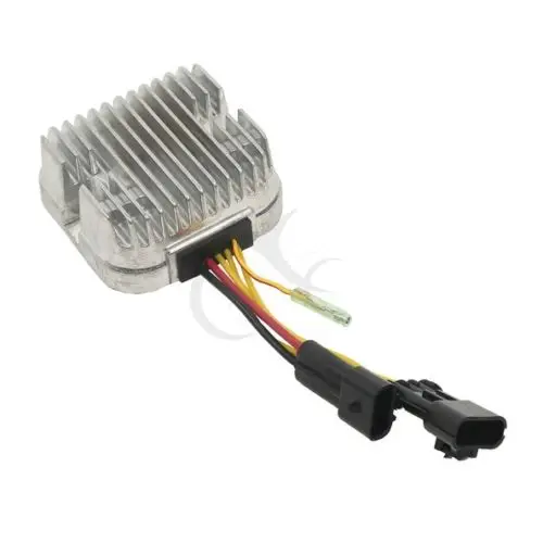 2 - 15.5 volts according to the manual.
My testimony, for comparison.
Engine not running, (ignition off), battery voltage. nine0113
Engine running, idling, headlight off.
With the engine running, RPM is 5000, headlight is on high beam. (It is advisable to keep the speed as accurately as possible in the region of 5000 rpm, as this affects the readings).
The result of the test shows that the voltage regulator relay is working properly.
Measurement results may differ for everyone, the main thing is to pay attention to two important indicators:
1. The voltage difference between the engine not running and running must be at least 0.7 volts. (For example, I have 12.35 volts at the idle voltage, and 13.2 volts at the running one, the difference is 0.9 volts, this is within the normal range).
2. Voltage under load with headlight at 5000 rpm must be at least 13 volts.
Important: If you are not sure about something, or the measurement readings do not give an accurate answer, then it is better to contact professionals.
Sale!
4,990.00 RUB
Product Quantity Kawasaki ATV Voltage Regulator Relay
Article: mr06kk Category: Kawasaki
Modern shunt regulator voltage rectifier (relay regulator) on MOSFETs. It produces a stable voltage, has protection against overheating and overvoltage, heats up less and lasts longer than other regulators. nine0113 Parameters:
Dimensions (width/height/thickness) — 90/105/32 mm
Distance between holes — 70 mm
Rated voltage — 14.