“A tire only loses air if it’s punctured.” This is a common misconception that we have all had or heard and yet the reality is quite different. Indeed, a tire can lose air even without a puncture, as for example in the case of a crack in the valve that is used to inflate your tires. A punctured valve is difficult to detect, and not taking care of it in time can have real consequences for your tire, but also (and above all!) for your safety. Blackcircles Canada, your online tire specialist, offers below a complete guide to the causes and consequences of a punctured valve, and how to repair a leaking valve stem.
A valve is a pin located on the outside of the tire, through which the tire can be inflated/deflated. It has a mechanism consisting of a spring-mounted valve that closes tightly with the air pressure inside the tire. Over time, the stem valve may become brittle and cracked, which may increase the risk of air leaking through it.
When the stem valve leaks, the affected tire is no longer able to retain air. Depending on the extent of the damage, the air will leak out slowly or more quickly. In both cases, the valve must be replaced.
If the air leakage is slow, you will be subject to the problems encountered by drivers driving with underinflated tires. Internal damage that can shorten the service life of the tire by up to a quarter, increased fuel consumption due to higher rolling resistance: the tire will damage faster, and your energy-efficiency will be significantly lower. The tire will also have poorer traction and the stability of your car will be reduced when cornering, not to mention the more pronounced deformation of the tire that increases its internal temperature, which can cause it to burst. Finally, an under-inflated tire increases the risk of hydroplaning. Tire pressure is thus very important!
 Here’s how to do it!Step 1: Make sure it’s your valve stem that’s leaking.
First of all, make sure it is the tire valve stem that is leaking. To do so, there’s a very simple trick! Apply a mixture of water and dishwashing soap to the valve with the cap removed. If bubbles start to appear, your valve is leaking. If this is not the case, and there is a definite air leak, it will be located elsewhere on the tire.
Step 2: Gather the right tools before you start!Before you begin, make sure you have all the necessary equipment to complete the replacement of the faulty valve stem.
For this, you will need the following:
You are now ready to start the process!
Step 3: Loosen the nuts on the wheel you are going to work on.
To do so, use the wrench mentioned in the previous step to loosen each of the lug nuts holding your wheel in place. Do this while the car is still on the ground.
However, for certain models of vehicles, it is possible that the wheel nuts have an anti-theft ring. If this is the case, you’ll have to use the appropriate special key to remove the locking nut(s).
Step 4: Raise your vehicle with the jack and then remove the wheel.First and foremost, make sure the handbrake is applied so that your vehicle is completely immobilized. Then, use your jack to lift your car. Be sure to position it on the right part of the chassis so that the car is properly supported. This will prevent any damage to the car and any bodily injury. Once your car is lifted, secure it on jack stands. Unscrew the wheel bolts completely, then remove the wheel. Finally, place the wheel on the ground flat, with the outside of the wheel facing up.
Step 5: Remove the valve stem core with the removal tool and let the tire deflate.
If you have not already done so, remove the valve cap. Then remove the valve stem core using the valve stem removal tool to release the air from the wheel, which should normally deflate completely on its own.
Step 6: Separate the tire’s bead from the wheel.For this step, use the sledgehammer in the following way: hit the tire sidewall with the sledgehammer in the same spot until you hear a crack or popping sound, and see the inside lip of the tire visibly break loose from the rim. This means that the tire has been successfully detached from the lip of the wheel.
Once the tire bead has been broken, continue hitting with the sledgehammer around the tire to detach the sidewall around the entire circumference of the wheel.
Step 7: Remove the tire from the rim.Once the sidewall of the tire is separated from the outer edge of the rim around the entire circumference of the wheel, insert your tire iron between the edge of the rim and the inside lip of the tire, and then pry upward to pull the lip of the tire over the edge of the wheel. Once you have pulled the lip of the tire over the edge of the wheel, work the tire iron around the rim until the entire lip of the tire is off the rim.
Once the sidewall of the tire is completely above the wheel, grab it by its removed lip and pull it upward so that the opposite lip that was at the bottom of the wheel is now touching the top edge of the rim. Use your tire iron again by inserting it between the tire’s lip and the edge of the wheel and pry upwards to pull the lip over the edge of the rim. As before, work the tire iron around the edge of the wheel until the tire is removed from the wheel.
Step 8: Remove the defective valve stem and replace it with the new one.Once the tire is separated from the rim, it is time to remove the valve stem. To do this, first pull out the valve stem free from the wheel using the needle-nose pliers. Once this has been done, install the replacement valve stem from the inside of the wheel. Once it is in position, use the needle-nose pliers again to pull it through into its right place on the wheel.
Once the stem is in place, it is time to put the tire back on its rim. To do this, start by pressing the tire down over the rim until the bottom bead clears the edge of the rim. The aim here is to return the lower sidewall of the tire to its original position on the wheel.
Then press the upper sidewall of the tire down underneath the edge of the wheel. Then tuck your tire iron between the tire sidewall and the rim edge and use it to make the opposite movement to the one you used to pull the tire sidewall out of the rim. Once the bead clears the lip of the wheel, use the tire iron to work your way round the entire wheel until the tire is completely installed on the wheel. Then inflate it to the correct pressure using the air compressor.
Step 10: Make sure there are no other leaks, and mount your wheel back on!Once the tire is inflated to the correct pressure, check for other leaks. If all is well, mount the wheel on your vehicle and bring it down by lowering the level of the jack stands until the repaired wheel touches the ground and you can safely remove them.
Ultimately, it is very important to make sure your tires are free of air leaks to maintain proper air pressure at all times. In the case of a slow air leak, the consequences can be dramatic. If the air leak is due to a faulty tire valve, you will definitely need to replace it. You can either follow the above procedure on how to repair a leaking tire valve or take it directly to a specialist. If, on the other hand, you need to change the entire tire, consult our selection of tires adapted for your car directly online on our website!
Tire Installation 101: When and how to change your tires?
Valve seals precisely control the amount of oil entering the valve stem system, making them critical components in maintaining your engine’s compression levels. Having a valve stem seal that works correctly within any of your applications can save you time and money by eliminating the need for lengthy engine repairs and replacements. But how do you check for bad valve seals, and what signs should you be aware of?
No one wants to face valve issues because they indicate a severe problem within your machine’s engine. Here is where Global Elastomeric Products comes into play. Learn how to find faulty seals and what you can do to avoid these issues.
Table of Contents
Valve stem seals control oil consumption and lubricant in an engine by allowing a specific amount of oil inside the valve stem as it moves. A controlled amount of oil is crucial in maintaining adequate lubrication. Otherwise, too little oil can cause various components to wear as parts rub together. However, excess oil can result in carbon buildup, which can lead to many issues, such as:
Essentially, valve stem seals prevent oil from entering the combustion chamber from the cylinder head. A damaged seal can cause engine oil flooding that will lead to engine failure.
Six ways to assess whether you have a faulty seal on your hands include:
One of the best ways to tell if you have a faulty valve seal is to conduct a cold engine test. After your machine hasn’t run for a while — even overnight — the seal is now cool. Once you start the engine, the seal will contract. Damaged seals will leave a small gap. Leftover oil will then settle at the top of the valve cover head.
When you start the engine, you may also see blue-tinted smoke appear from the exhaust. If this happens, it means the residual oil is passing down through the damaged seal and into the combustion chamber. The bluish smoke, which is burned oil, signifies that the engine needs a new seal, even if it clears after several minutes of running the engine.
Depending on the machines and equipment you use, smoke is often a common form of exhaust. However, when you start seeing it last longer than usual or appear a different color, you know a faulty seal may be the cause. The excessive smoke may also come in more consistent waves as the engine runs for long periods. Be aware of specific machine movements that cause more smoke than usual.
If you notice you’re going through more oil than usual, it can be another indication of a bad seal. When oil leaks or burns at higher rates, the seal no longer controls the oil flow. Burning oil increases emissions and can contaminate the catalyst. Unburned fuel in the exhaust skyrockets the converter’s operating temperatures, which can cause the converter to overheat and create a blocked exhaust.
Make sure to check the engine’s oil level with a dipstick, and refer to your oil log to see if the fluid levels differ. You can make this part of your regular maintenance schedule. While oil leaks are often a clear warning of faulty valve seals, they may not always be visible, so don’t rely on this as a guaranteed warning because the oil could be burning off.
Pay attention to your machines if they ever idle. When the engine is at rest, high vacuum levels can cause the oil to build around the heads of the valve system while the valve is closed. If the seal is faulty, you may once again see blue-tinted smoke when the engine begins to run. That means the oil is getting pulled past the seal and into the valve guide. Make sure to shut the engine down and remove it from operation until you can get it repaired.
Depending on the engines you use in the oilfield and agricultural industries, testing the engine’s compression can also help determine if your valve stem seals are deteriorating. If the machine has a higher compression level, you have a valve seal issue and you'll need replacements. On the other hand, a lower level may designate a piston ring malfunction.
An engine with broken seals can cause oil to build on the electrodes of the engine’s spark plugs. As a result, plug fouling can occur, which is an accumulation of carbon deposits that can cause engine misfires. As carbon buildup increases, so does compression, leading to engine damage from faulty detonation or even issues with pre-ignition.
Knowing these six signs of valve stem seal failure can help you mitigate the issue before problems like oil leaks and high compression levels begin. The sooner you notice different-colored smoke, an increase in oil usage, misfiring engine startups and idle noises, the faster you can make the necessary seal repairs. In return, your operations will remain efficient, productive and safe.
The main causes of a deteriorated seal come from faults within the seal itself and improper installation. Even though valves consist of high-strength rubber, they can break, crack or wear down. Seals could even be missing from a botched installation. Any of these faults in the seal will cause oil to reach the engine’s cylinders.
As valve stem seals begin to fail, carbon buildup forms, which also affects other engine components like the valve seat and guide — which is why quick repairs are critical.
In some cases, there still may be excellent compression. However, if high oil consumption is present, it will then cause higher operating temperatures that can lead to broken or cracked seals. Seal problems can also form from an improper clearance between the valve and valve guide. When it’s loose within the cylinder head, it can move laterally, wearing out the valve.
The best thing you and your crew can do is refer to your preventive maintenance schedule for each piece of equipment in your fleet and complete regular safety checks.
Daily or weekly inspections will help you find leaks and problems before they become more severe.
It’s also essential to invest in top-quality valve seal solutions that are free of defaults. Partnering with a company that guarantees seal products with no defaults places you ahead of the competition, giving you a competitive advantage.
Because many factors can indicate a bad valve stem seal, you’ll have to investigate and not always rely on the various signs. If you have the appropriate training and qualifications, go ahead and start your inspection. Otherwise, rely on the experts for guidance.
Open the hood to the engine and check the oil level of your machine using a dipstick. Is it significantly lower compared to other times after a similar amount of usage? You can also check to see if there is any excess clearance between the valve stem and guide. Leaks are an obvious sign the valve stem seal has issues — but these aren't always present, even when the seal is failing.
Start the engine and observe the exhaust. Is there a lot of smoke coming out of the pipe, and does it have a blue-gray tint? If so, the engine is burning leaked oil — which is why you may not see any leaks under the hood.
Listen for odd noises like rattling or tapping as the engine idles. Any unusual sounds can indicate problematic valves.
Check for engine and error lights that can indicate a problem. You can hook the machine up to a diagnostic reader to scan for different error codes. For example, valve seal and valve guide issues will read as specific codes, so reference the owner’s manual for assistance.
If worse comes to worst, you will need to disassemble the engine and inspect the valve stem seals and other components. Relying on the professionals for this step may be best to ensure more parts do not get damaged throughout the process. You or the expert should look for dented, cracked, broken or deteriorated valve seals.
Valve stem seals' replacement costs are affordable in the long run because new seals prevent more catastrophic engine damage.
If oil is leaking from your engine, you’ll want to find a temporary, stopgap solution until you identify the issue and make repairs. For example, you can use an oil stop-leak additive in the oil filler, just like you would with regular engine oil. The additive will give the valve seals a quick fix by causing them to expand, creating a rapid extension of life.
You can also add high-mileage oil with seal conditioners that can slow or stop oil leaks. This type of oil keeps the seals pliable to help prevent corrosion.
Once you make a short-term fix, it’s crucial to start on repairs or replacements right away. Prolonged valve failure can affect the entire engine and hydraulics system, costing you expensive repairs or replacements in the future.
Failed parts can also affect your workers' safety and well-being. Your machine may begin to operate hazardously with a jolt of power or faster/slower movements than usual.
Once you’ve taken the correct preventive measures, replace the leaking seals using the following steps:
 Place the cover back on.
Fast valve stem seal replacements are just as essential as choosing a manufacturer that knows the vitality of a well-designed valve stem seal. Look for custom solutions that can fit your specific requirements if your machines are unique to your industry or operations.
You will want to invest in top-tier solutions that are free of defaults. For example, Global Elastomeric Products has an inventory of rubber seals that provide an elastomeric seal for your engines. We focus our valve seal portfolio on durable, temperature- and chemical-resistant solutions. We can also manufacture any customized rubber compound to fit your unique needs.
Our packer elements and valve seals include:
Quality means everything when you’re trying to meet your oil or agricultural industry quotas, including valve seals. Your business needs to rely on elastomeric products that produce defect-free replacement parts just as much as you count on efficient employees on your rig. If you neglect quality, you can put your operations and workers at risk of breakdowns and injuries.
Functional valve stem seals are crucial in keeping your operations efficient. Whether you work in the agricultural, oil or another industry, your machines drive daily operations. If you’re experiencing seal leaks, deterioration or damage, Global Elastomeric Products has what you need.
We guarantee our standard and custom in-house seal designs will be free of defects. Our experts design, manufacture and distribute our valve seal product lines while keeping your specifications at the forefront of each customization. We can generate product designs and engineer seals for any oil field or agricultural application. Global Elastomeric Products is the solution to your leaking and damaged seals.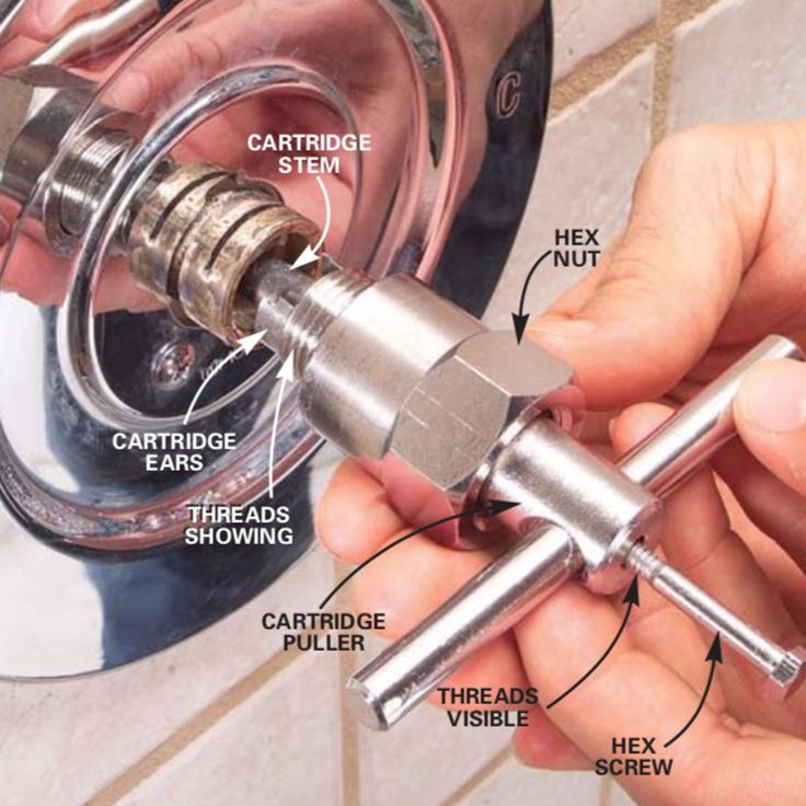
Reach out to us online with questions or for more information about our solutions. You can also request a free quote by calling us at 661-831-5380 to help you better understand our valve stem seal products.
Safety shut-off electromagnetic valves PKNE-200, PKVE-200 (PKEN-200, PKEV-200)
are semi-automatic shutoff devices designed to hermetically shut off the supply of non-aggressive hydrocarbon gases. they close when the controlled pressure goes beyond the set upper and lower limits, as well as in automatic control systems for gas-using devices when the voltage on the electromagnet is turned off. Valves are opened manually. Arbitrary opening of valves is excluded. nine0005
The operating conditions of the dampers must comply with the climatic version UHL 2 GOST 15150-69 with an ambient temperature of minus 35 to plus 45 0 C. The dampers may not be installed in hazardous areas.
Valves are manufactured with nominal diameters DN 50, 100 and 200 low PKNE or high PKVE controlled pressure.
Specifications
Under 15 years of operation, the product is subject to disposal of
The device and the principle of operation
Corps 1 of the valve type is connected to the transition flange 2 . Cover 3 is attached to the adapter flange. Between the cover 3 and the adapter flange, a membrane 4 is clamped, the effective area of which for the PKV type valve is 8.5 times less than for the PKN type valve. In lid 3 , a large spring 5 is installed, the force of which is changed using the plug 6 , and a small spring 7 , the force of which is changed using the stem 8 . Inside the body 1 there is a valve 9. The sleeve of the valve 9 moves along the guide post 10 screwed into the body, and the valve stem 4 0 90 04 into the bore of the adapter flange 2.0
Valve lift 9 is carried out with the help of a fork 12, mounted on a rotary shaft 13 , at the end of which a lever 14 is attached.
Valve 9 has a device that acts as a bypass valve to equalize the gas pressure before and after valve 9 when it is opened. When the valve is opened, lever 14 engages with anchor lever 15, mounted on adapter flange 2 . The rocker 16 , installed in the lid 3 , is connected by one end with the membrane 4 , and the other with a hammer 17
to open a valve, you need to raise a lever 14,0004 until it is engaged with an anchor lever of 15 .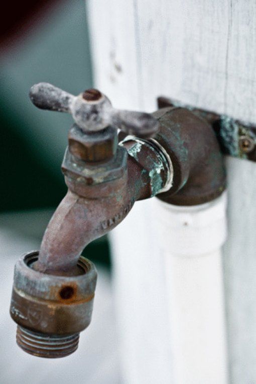 At the same time, the valve 9 rises and opens the passage for gas, which from the network through the impulse tube will enter under the membrane 4. The valve is adjusted to the lower response range by rotating the stem 8 , and on the upper range - by turning the plug 6 .
If the controlled gas pressure is within the specified limits, the rocker 16 , connected at one end to the diaphragm 4 , the other end will be aligned with the hammer stop 17 , which will be locked in a vertical position, raised manually.
If the controlled gas pressure rises above the set upper limit set by the large spring 5 , diaphragm 4 , overcoming the force of this spring, will go up and turn the rocker 16 , the outer end of which will disengage from the hammer stop 17 . Under the action of the load, the hammer 17 will fall and hit the free end of the anchor lever 15 , which will release the lever 14, fixed on the shaft, and the valve 9 under the action of its own weight and the weight of the load of the lever 14 will rest on the seat of the body of the lever 14 1 and block the gas passage. If the controlled gas pressure falls below the set limit set by the small spring 7 , diaphragm 4 under the action of this spring will go down and lower the inner end of the rocker 16 . This will disengage the outer end of rocker arm 16 from the hammer stop, which will fall and close the valve.
Electric actuator 18 is mounted on a bracket to the upper part of the cover 3. It is connected by a rod to the rocker arm 16 of the anchor-lever valve system.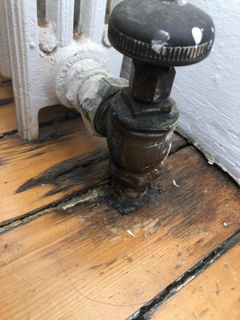
The gas supplied to the valve passes through the inlet pipe to the outlet, if to the actuator solenoid 18 Voltage applied. When the voltage supply to the electromagnet is interrupted, the rod 19 moves up, the tip of the rocker arm 16 will disengage from the hammer pin. As a result, the valve will be closed.
The valve is brought into the operating position after actuation by manually engaging the hammer pin with the rocker 16.
1 - housing; 2 - adapter flange; 3 - cover; 4 - membrane; 5 - a large spring; 6- cork; 7 - small spring; 8 - stock; nine- valve; 10 - guide post;
12 - fork; 13 - rotary shaft; 14 - lever; 15 - anchor lever; 16- rocker; 17- hammer; 18 – electric drive; 19 - thrust.
Safety Instructions
The valves must be installed and operated in accordance with the Gas Safety Regulations
The valves must be installed so that the direction of gas flow coincides with the direction of the arrow on the valve body.
The valve must not be installed in environments that are corrosive to aluminium, cast iron, steel, rubber and zinc coating.
All installation work must be carried out with process piping depressurized and power off.
The connection of the electromagnet to the mains supply must be in accordance with the general valve control scheme, "Electrical Installation Rules (PUE)".
The valve must be earthed, for which a Ø 20 mm pad is cleaned around the earth bolt and the earth wire is connected with a bolt made of non-corrosive material. In places where the power wires pass through the screen of the electromagnet, install ebonite bushings. nine0005
In order to avoid accidents and accidents, it is prohibited:
- to start working with the valve without reading this instruction manual;
- Troubleshoot or repair an operating valve;
- if you smell gas near the valve installation site, smoke, light matches, turn on and off the electric lighting (if it is not made in an explosion-proof version)
Mounting and preparing the valve for operation
Before installing the product, it is necessary to depreserve the outer surfaces.
Installation of the device in places with a negative temperature is allowed provided that there is no condensation of water vapor in the passing gas at these temperatures.
The valve is mounted on a horizontal section of the pipeline in front of the pressure regulator. The membrane must be in a horizontal position. The gas inlet must correspond to the arrow cast on the body. The valve with its supporting surface is mounted on brackets or stands and does not require additional fastening. the direction of the slope, in which condensate can accumulate. Connection of a tube to the lower quarter of a horizontal pipeline in which pressure is controlled is not allowed. If, according to the installation conditions, such an arrangement is inconvenient, then it can be remounted. To do this, unscrew the nuts, remove the assembled head, swap the plugs and turn the fork axle over. Place the lever on the axle so that the axis of the lever bar coincides with the direction of the fork axis in the same plane, then fix the lever with a nut. Install the head by turning it 180 0 relative to the original position and tighten the nuts. After mounting and remounting the valve, check the reliability of knocking out the anchor with a hammer, the tightness of all connections with air, nitrogen or working gas at a pressure of 1.2 MPa. All sealing points of the sub-membrane cavity of the adapter flange shall be pressure tested for tightness: for PKN-0.1 MPa valves, for PKV-0.6 MPa valves. For the tightness of closing the valve with a pressure of 1.2 MPa and 0.002 MPa. Air leaks at the joints and seals are not allowed. nine0005
The valve must be sealed after adjustment by the user to the desired set pressure.
Operating procedure
After installation and pressure testing of the valve, it is necessary to adjust the operating parameters.
The following setting order is recommended.
First set the lower limit by turning the stem 8.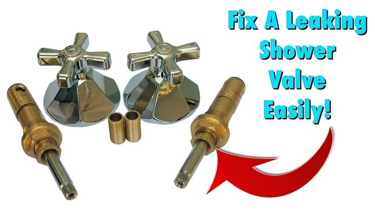 During the adjustment, keep the pressure in the impulse tube slightly above the set limit, and then slowly reduce the pressure and check that the valve operates when the pressure drops to the set lower value. nine0005
Then set the upper limit by turning plug 6. During the adjustment, keep the pressure slightly above the set lower limit. After finishing the adjustment, increase the pressure and make sure that the valve operates when the upper limit is reached.
When opening the valve after it has actuated, engage the hammer pin with the rocker only after eliminating the causes of the impermissible pressure change by pressing the diaphragm stem. In this case, the pressure in the head is recommended to be maintained slightly above the lower limit. nine0005
If the hammer does not move to the working vertical position at normal controlled pressure, then the valve should be checked for proper operation.
Maintenance
During valve operation, preventive inspections should be carried out at least once every three months, and preventive maintenance - once every one and a half years.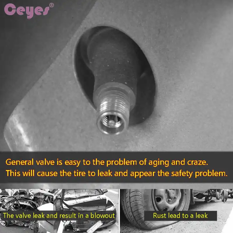
On inspection, check that the valve operates within the predetermined pressure limits, as well as that it rotates easily on the hammer and anchor lever axes. nine0005
The valve stem must move freely on the guide column. If necessary, clean the stem and guide column. To avoid dust settling, do not lubricate the guide.
The valve seat must be clean. Clogged seat causes valve leakage. Pay attention to the condition of the rubber seal. Over time, the rubber loses elasticity, which can cause leakage when the valve is closed.
Troubleshooting
Transportation and storage of valves
10.2. During long-term storage in a warehouse, valves must be re-preserved after one year of storage with conservation oil K-17 GOST 10877-76 or other lubricants for products of group II according to the protection option VZ-1 GOST 9.014-78
Shelf life no more than 6 years.
10.3. It is allowed to transport valves in universal containers without packaging with laying products in rows, separating each row with gaskets made of boards, plywood, etc.
Warranty period - 18 months 50, PKVE-50, PKVE-200, PKNE-200 with aluminum alloy body
In addition to the solenoid valve PKEV-200 (PKVE-200), the delivery set includes: certificate of conformity, permission to use, passport, outline diagram PN 16, DN 25-100 - Sibir-Promkomplekt
| Safety valve 17s28nzh is designed to protect equipment from unacceptable overpressure by automatically dumping excess working medium into the atmosphere or the outlet pipeline. Valves 17s28nzh are leaky in relation to the external environment. These valves are installed in pipelines using a flange connection to prevent accidents associated with an increase in pressure in the system. When the safety valve is actuated, some of the working medium is discharged, due to which the pressure in the system normalizes. After the pressure has reached the standard value, the valve closes automatically. Specifications
|
| Nominal inlet diameter DN, mm | 25 | 32 | 40 | 50 | 65 | 80 | 100 | |
| Nominal inlet pressure PN in x , MPa (kgf/cm 2 ) | 1. 6(16) 6(16) | 1.6(16) | 1.6(16) | 1.6(16) | 1.6(16) | 1.6(16) | 1.6(16) | |
| Nominal outlet diameter DN1, mm | 40 | 50 | 65 | 80 | 100 | 100 | 150 | |
| Outlet flange pressure rating PN out , MPa (kgf/cm 2 ) | 0.6 (6) | 0.6 (6) | 0.6 (6) | 0.6 (6) | 0.6 (6) | 0.6 (6) | 0.6 (6) | |
| Seat area Fc, mm 2 | 201 | 201 | 314 | 491 | 855 | 1256 | 1809 | nine0351|
| Flow coefficient α, min | for gaseous media | 0.6 | 0.6 | 0. 8 8 | 0.8 | 0.8 | 0.8 | 0.8 |
| for liquid media | 0.1 | 0.1 | 0.5 | 0.5 | 0.5 | 0.5 | 0.5 | |
| DN25 | DN32 | DN40 | DN50 | DN65 | DN80 | DN100 |
| kgf/cm 2 (spring no.) | ||||||
| 0.5-2 (6) | 0.5-2 (6) | 0.5-1.5 (6) | 0.5-1.5 (0) | 0.5-1.2 (10) | 0.5-1.5 (30) | 0.5-1 (50) |
| 2-4 (7) | 2-4 (7) | 1.5-3.5 (7) | 1.5-3.5 (1) | 1.2-2.5 (11) | 1.5-3.5 (1) | 0.8-1.6 (51) |
| 4-8 (8) | 4-8 (8) | 3. 5-7 (8) 5-7 (8) | 3.5-7 (2) | 2.5-4 (12) | 3.5-7(2) | 1.5-3 (52) |
| 8-16 (1) | 8-16 (1) | 7-10 (1) | 7-10 (3) | 4-8 (13) | 7-10 (3) | 2.5-4.5 (53) |
| 10-16 (2) | 10-16 (4) | 8-16 (14) | 10-16 (4) | 4.5-8.5 (54) | ||
| 8-16 (55) | ||||||
Call (383) 373-25-05 | | nine0351
| DN | D1 | D2 | D3 | L | DN out | D4 | D5 | D6 | L1 | H | dc | n | d | n1 | d1 | Weight, kg |
| 25 | 68 | 85 | 115 | 100 | 40 | 80 | 100 | 130 | 70 | 385 | 16 | 4 | 14 | 4 | 14 | 11. 4 4 |
| 32 | 78 | 100 | 135 | 105 | 50 | 88 | 110 | 140 | 75 | 390 | 16 | 4 | 18 | 4 | 14 | 12.7 |
| 40 | 88 | 110 | 145 | 115 | 65 | 110 | 130 | 160 | 85 | 395 | 20 | 4 | 18 | 4 | 14 | 13.6 |
| 50 | 102 | 125 | 160 | 130 | 80 | 124 | 150 | 185 | 90 | 420 | 25 | 4 | 18 | 4 | 18 | 17.5 |
| 65 | 122 | 145 | 180 | 140 | 100 | 148 | 170 | 205 | 120 | 510 | 33 | 4 | 18 | 4 | 18 | 24.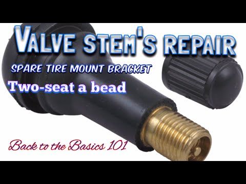 1 1 |
| 80 | 132 | 160 | 195 | 150 | 100 | 144 | 170 | 205 | 135 | 510 | 40 | 8 | 18 | 4 | 18 | 26.5 |
| 100 | 180 | 156 | 215 | 160 | 150 | 240 | 211 | nine0347 280200 | 720 | 48 | 8 | 18 | 8 | 22 | 58 |
(383) 373-25-05 | |
| nine0785 (383) 291-75-77 | |
or send your supply request: | |
 PN 16, DN 25-150
  PN 40, DN 32-150 nine0368
 | By choosing Sibir-Promkomplekt as your equipment supplier, you not only get high-quality goods from leading manufacturers at one of the lowest prices, but also our following advantages: |
Experience All our specialists have extensive experience in the field of supplying enterprises with equipment. Comprehensive consultationOur specialists offer comprehensive advice on all issues at all stages of the transaction - from the first call, at the stage of selecting the necessary equipment, to the delivery and transfer / exchange of the necessary documentation. Always low pricesOur company offers the most competitive prices on the market. As a result of direct cooperation with the manufacturers of our specialized equipment, we guarantee one of the lowest prices for all our commodity items! nine0005 Complex ProcurementWe specialize in fulfilling complex, complex needs, requests containing various types of equipment and materials, including those not included in our main catalog! |
Long-term cooperationOur company aims to become your permanent supplier, offering the most favorable conditions for you! Therefore, we always comply with all the terms of the transaction "from and to"! nine0005 PunctualityCooperating with us, based on the extensive experience of our specialists, be sure that all stages of delivery will be completed within the allotted time! We will find a solution We will find and select equipment and materials specifically for your needs. |