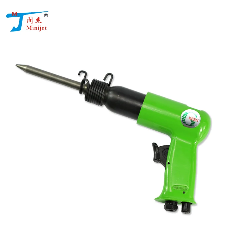
We offer following high quality hydraulic Bead Breakers from AME International.
Wheels up to 25”
• Single, 2 and 3 piece wheels
• Most popular tool for breaking beads on all agricultural wheels
• Tool clamps hydraulically with 11 tons of force
• Use with any 10,000 psi (700 bar) air/hydraulic pump
• Stroke length: 9.5 cm
• Weight: 15.5 kg
Product no.: 900439
Wheels up to 25”
• Single, 2 and 3 piece wheels
• Least expensive bead breaker for new 3 piece wheels
• Larger clamp and feet allow tool to easily clamp onto wheels
• Compact design allows the tool to be used on the front or back side of wheel
• Use with any 10,000 psi (700 bar) air/hydraulic pump
• Stroke length: 9.5 cm
• Weight: 17 kg
Product no.: 900440
TITAN Earthmover tyre Bead Breaker
• Ideal for tyre dealer who requires occasional use of bead breaker
• 10 ton cylinder has enough force to break most beads
• Unit will work on 5 piece wheels with bead loosening pockets
• Stroke length: 10 cm
• Weight: 15.5 kg
Product no.: 900441
Stinger Bead Breaker
• Lightweight option for breaking 3 piece wheels
• Unit mechanically clamps to wheel, regardless of size or clearance
• 10 ton stroke cylinder pushes bead back away from the wheel
• Unique head is designed for tool to push on the bead – not the sidewall of tyre
• Comes with 2 spacer wedges to prevent bead from re-seating
• Shipped with tool box
• Stroke length: 20 cm
• Weight: 13 kg
Product no.: 900442
For 25” and 29” earthmover wheels
• Compact, lightweight tool
• Works only on 5 piece wheels with bead loosening pockets
• 10 tons of hydraulic force
• Used with any 10,000 PSI (700 bar) air/hydraulic pump
• Stroke length: 5. 4 cm
4 cm
• Weight: 10 kg
Product no.: 900447
Wheels from 25” up to 51”
• Most popular tool for breaking beads on earthmover tyres
• Works only on 5 piece wheels with bead loosening pockets
• Use with any 10,000 psi (700 bar) air/hydraulic pump
• Stroke length: 10.8 cm
• Weight: 14.5 kg
Product no.: 900443
Wheels from 39” up to 63”
• Bead Breaker for use on 39” up through 63” earth mover wheels
• Used with large capacity (5 quart or more) 10,000 PSI (700 bar) air/hydraulic pump
• Stroke length: 15.25 cm (breaks all beads)
• Weight: 23.5 kg
Product no.: 900444
Wheels from 51” up to 63”
• Designed specifically to work on Topy and Rimex OE wheels
• Designed to prevent the tool from kicking out while under load
• Stroke length: 15. 9 cm
9 cm
• Weight: 24.5 kg
Product no.: 900446
Earthmover tyre bead breaker
• Works on 5 piece wheels which do not have bead loosening pockets
• Includes 6 curved wedges which are used to prevent tyre from ‘re-seating’
• Used with any 10,000 PSI (700 bar air/ hydraulic pump
• Stroke length: 25.4 cm
• Weight: 23.5 kg
Product no.: 900448
Combi Bead Breaker Kit
1 x Bead Breaker (model no. 11010)
1 x Air Hydraulic Pump (model no. 15900)
- Builds 10,000 PSI of pressure
- Oil Capacity: 2.36 Liters (2.5 Quart)
- Reservoir Type: Polyethylene
1 x Hydraulic hose (model no. 16040)
- 10,000 psi (700 bar) working pressure
Product no.: 900449
Combi Bead Breaker Kit
1 x Bead Breaker (model no. 11010)
1 x Air Hydraulic Pump (model no. 15920)
- Builds 10,000 PSI of pressure
- Oil Capacity: 4.7 Liters (5 Quart)
- Reservoir Type: Steel
1 x Hydraulic hose (model no. 16040)
- 10,000 psi (700 bar) working pressure
Product no.: 900450
Dual Combi Bead Breaker Kit
2 x OTR Giant Tyre Bead Breaker (model no. 11000)
1 x Air Hydraulic Pump (model no. 15920)
- Builds 10,000 PSI of pressure
- Oil Capacity: 4.7 Liters (5 Quart)
- Reservoir Type: Steel
2 x Hydraulic hoses (model no. 16040)
- 10,000 psi (700 bar) working pressure
1 x 8’ hydraulic hose rated at 10,000 PSI (model no. 16100)
1 x Hydraulic Manifold Kit (proper couplings included) - model no. 16165
Product no.: 900451
For Bead Breaker no. 11044
• Adapter for TOPY Wedge Wheel Bead Breaker Extension
• Designed to work on TOPY Wedge Wheels
• Does not scar/contact rim base
• Shorter rim flange sections
• Can be added to 11044 in minutes, thread in install
Product no. : 900453
For Bead Breaker no. 11044
• Adapter for 11044 Titan SVM/ OVM Wheel
• Does not scar/contact rim base
• Designed to work on narrow bead seat bands
• Can be added to 11044 in minutes, snap in install
Product no.: 900454
For Bead Breaker no. 11044
• Adapter for 11044 Rimex DGS Wheels
• Does not scar/contact rim base
• Designed to work on narrow bead seat bands
• Can be added to 11044 in minutes, snap in install
Product no.: 900455
For Bead Breaker no. 11044
• Extended Clamping Frame fits over Sur-Loc Bead Bands
• High Chromoly Steel ensures structural integrity in the toughest conditions
• Can be added to 11044 in minutes, snap in install
Product no.: 900456
 11046
11046 For Bead Breaker no. 11044
• Contains two jaws for back section and bead bands
• High Chromoly Steel ensures structural integrity in the toughest conditions
• Fits majority of 5 Piece OTR Wheel assemblies
• Can be added to 11044 in minutes, snap in install
• Not to be used on CAT Shur-Lok assemblies model no.11043
Product no.: 900457
ESC-10165
Esco ESC300 Dual Wheel Farm Tractor Tire Bead Breaker
$1,245.00
AME-11000
AME Giant Tire Bead Breaker (For 5 Piece Wheels)
$808.00
1 reviewESC-10201
ESCO 10201 "COMBI" Bead Breaker Kit (2. 5 Qt)
5 Qt)
$1,319.95
MTP-BB-501
MTP BB-501 Hydraulic Bead Breaker (3/8" FTP)
$429.00
ESC-10102
Esco 10102 Maxi Bead Breaker
$894.95
ESC-10839
Esco 10839 Yellow Jackit Combi Bead Breaker Kit
$1,239.95
AME-11060
AME Dual Agricutural Tire Bead Breaker
$644.00
ESC-10103
Esco 10103 Giant Tire/Earth Mover Bead Breaker
From $484.95
ESC-10820
Esco 10820 Yellow Jackit Combi Bead Breaker Kit
$809.95
ESC-10202
Esco 10202 Combi Bead Breaker Kit
$1,474. 95
95
AME-11080
AME Bead Push Off Tool, with 4 ton Ram, 5-1/2 in Stroke
$292.00
ESC-10109
Esco Talon Bead Breaker For Heavy Duty 3 Piece Rims
$1,279.95
AME-11076
AME Diamondback Aluminium Bead Breaker
$1,950.00
ESC-10104
Esco 10104 Giant Tire Bead Breaker
$1,124.95
ESC-10107
Esco 10107 Euro Style Aluminum Bead Breaker
$1,434.95
AME-12105
AME Dual 11000 Bead Breaker Kit
$3,304.00
ESC-10106
Esco 10106 Dual Agricultural Tractor Tire Bead
$574. 95
95
AME-11040
AME Tire Bead Breaker
$2,120.00
AME-11030
AME AEM OTR Giant Tire Bead Breaker
$1,824.00
AME-11020
AME Modified Combi Tire Bead Breaker
$1,000.00
201
Warning
•
This conditioner is not designed for children, elderly or sick people without supervision. nine0004
PRECAUTIONS
CAUTION
When replacing the air filter
, do not touch the
metal parts
of the indoor unit.
•
This may cause injury.
Before cleaning the
, turn it off and unplug the
power cord or
turn off the mains breaker
.
•
Because the fan blades
rotate at a high speed
, injury may result.
Do not touch the
switches with wet hands.
•
Doing so may cause electric shock to
.
Do not wash the
air conditioner with water.
•
Water can get inside the appliance
and damage the insulation. Doing so may cause
an electric shock.
Protect domestic animals and plants
from direct exposure to
air flow.
•
This is harmful to animal health
and plants.
Do not use
insecticides or
flammable aerosols.
•
Doing so may cause a fire or
deformation of the body of the instrument.
Do not use
intermediate connector in
power cord or
extension cord.
It is forbidden to connect
several electrical appliances
to one AC source
.
•
Poor connections, insufficient
insulation, connection to a higher voltage
network, etc.
may cause fire or
electric shock. nine0004
Do not cut or modify the
power cord in any way.
•
Do not place heavy objects
on the power cord, cut
or modify it in any way. Doing so may damage the
power cord and result in a
fire or electric shock to the
.
It is forbidden to turn on /
turn off the circuit breaker in the
power supply network or
disconnecting/connecting
the power cord plug while the appliance is
in operation.
•
This may cause a fire due to
sparking, etc.
•
Be sure to turn off the mains breaker
or unplug the power cord plug
from the outlet after turning off the
indoor unit with the
remote controller.
Protect skin from prolonged
exposure to cold air.
•
This is bad for your health.
If any abnormal symptoms
appear (smell of
burning, etc.), immediately stop the
air conditioner and disconnect the power cord
from the mains or turn off the
mains breaker.
•
Continuing to operate the instrument under
abnormal conditions may result in fire,
breakdown, etc. In this case
You need to contact your
dealer.
Do not insert fingers, sticks
, etc. into the air inlets /
air outlets.
•
Because fan blades
rotate at high speed, this
may cause injury.
•
Small children should be supervised
and should not play with the air conditioner
. nine0004
The user is prohibited from carrying out repairs
and moving the air conditioner
by himself.
•
Incorrect repair and handling
may result in fire,
electric shock,
injury due to falling instrument,
fluid leakage, etc.
Contact your dealer.
User installation of this device
is prohibited.
•
Incorrect repair and handling
may result in fire,
electric shock,
injury due to falling instrument,
fluid leakage, etc.
Contact your dealer.
Ventilate the room in which
the appliance is used
together with a stove or
similar equipment.
•
This can lead to a lack of
oxygen. nine0004
Do not use the
instrument for purposes other than those intended.
•
Do not use this
air conditioner to store
precision instruments,
foodstuffs,
animals, plants, or
art objects.
This may adversely affect their quality
, etc.
It is forbidden to install stoves
or similar equipment
in the area of direct air flow
. nine0004
•
This may result in incomplete combustion of combustibles
.
The breaker cam must be in a precisely fixed position relative to the crankshaft. The position of the generator rotor is determined by a pin on the crank pin and a groove in the rotor hub. The position of the cam in relation to the rotor is determined in the same way. On the inside of the cam there is a groove that fits over the drive lug in the rotor bore. Tap the cam gently in an axial direction to move all the parts into place. The cam rests against the rotor, the rotor against the crank pin.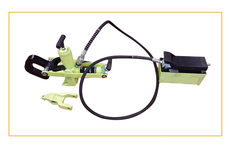 All parts are tightened with a central screw with a washer. Install the stator. The assembly is completed by adjusting the ignition timing. nine0005
Among the possible malfunctions of the generator, one more should be attributed, which, however, does not occur often. This is a short circuit in the rotor winding. A malfunction, most likely, may appear as a result of careless handling during generator repair, if the rotor is left after disassembly among various parts or tools. The winding of the rotor, which is usually placed on the table after disassembly, is very vulnerable. It can be easily damaged by sharp edges. If a damaged rotor is installed in a generator, induced currents form parasitic circuits and the generator does not develop sufficient power. nine0005
The excitation winding on the stator is subjected during manufacture to such tests and controls that no faults are observed in subsequent operation. Damage does not appear during repairs either, since the winding is located inside the stator, and therefore is sufficiently protected from careless handling and mechanical damage.
If the breaker cam felt is impregnated with lubricant, mechanical damage to the breaker is rare. This may be a crack in the spring that presses the breaker hammer against the fixed contact. With such a malfunction, misfires immediately appear or it is absent. The malfunction is eliminated by installing a new breaker hammer and adjust the ignition timing. nine0005
More common is a malfunction in the electrical system of the breaker. The breaker contacts disconnect the primary circuit of the ignition system, but when the contacts are broken, an electric arc occurs between them. At the same time, the breaker contacts burn, their surface oxidizes. Oxides can form a bump on one of the contacts, which, firstly, is a poor conductor and, secondly, changes the gap and ignition timing. As a result, misfiring occurs, "shots" in the engine, its power drops significantly. nine0005
The contacts are cleaned with a flat file or, better, with a strip of sandpaper, which is folded along the length with the cloth inside. The strip folded in this way is inserted between the closed contacts and pulled back and forth several times until their working surfaces are clean and shiny. Then the contact surfaces are cleaned with a cloth soaked in gasoline to remove dust. Check and, if necessary, adjust the ignition timing again.
The primary ignition circuit starts at the power source, goes through the ignition switch and the primary winding of the ignition coil, through the insulated breaker hammer to the fixed contact, and from it to the generator ground. There is no danger of a short circuit in the primary circuit. The only vulnerable point is the breaker terminal, the fastening screw of which must be insulated from the base of the contact. The insulation is provided by two square Pertinax spacers and a round insulating insert in the base hole. nine0005
If any of the insulating gaskets are damaged (for example, cracked due to overtightening or careless assembly), a short circuit occurs in the primary circuit and the ignition does not work. Such damage is unacceptable, but it is usually invisible from the outside. Therefore, it is best to conduct an insulation test. For safety reasons, we will remove the generator stator from the engine (or the base with the breaker installed on it) and we will work on a wooden table or on a sheet of other material with good insulating properties. nine0005
166
On motorcycle mod. 634, the output of the capacitor is made differently: it is fixed to the breaker with a spring of the breaker lever. In this version, the terminal insulation must be rechecked. To do this, use alternating current with a voltage of 220V. A 15 or 25 W lamp is included in the test circuit (Fig. 191). One phase is connected through a lamp or to the breaker terminal or to the lug of the wire going to the breaker (for older generators), which is previously disconnected from the 1A or 1B terminal on the main terminal panel of the generator. Insert insulating tape, pertinax or other insulating material 0.5 mm thick between the interrupter contacts. nine0005
If there is a short circuit in the circuit, the circuit is closed through the generator ground and the lamp is on. If, on the contrary, the breaker terminal is well insulated, then the test circuit cannot be closed (the breaker contacts were mutually insulated before the test), and the lamp should not light. If damage to the insulation of the breaker and its terminals is established, the breaker is disassembled in the manner already described, the gasket is replaced. Nowadays, capacitor failures are very rare. In addition, they are easily identified by the uneven operation of the engine and the sparking of the interrupter. If its contacts spark strongly, then the capacitor is either poorly connected to the generator ground, or its wire is broken. The wire and its insulation are checked. The metal surface of the capacitor must be in contact with the ground of the motorcycle, which has good conductivity, and the capacitor wire must not be broken anywhere. If there are signs of oxidation on the metal surface (i. e., the surface is not clean and shiny), then it is cleaned and thus a reliable conductive contact is ensured. Then the tip of the wire is tightened. nine0005
If the motor shaft is turned by the starting pedal, and there is no sparking of the breaker contacts, then the capacitor is probably broken and needs to be replaced. The condition of the capacitor can be checked in a simple way. It is removed from the engine, connected to a 220 V AC test circuit (lighting network), and connected as shown in fig. 192, a measuring device (best of all, an ampervoltmeter). An ammeter connected to a circuit with a 15 or 25 W test lamp should, with a good capacitor, show a current of approximately 20 mA in both cases, because the alternating current partially passes through the capacitor. nine0005
11.Relay-regulator with one solenoid coil
∙а) Operation check and adjustment. The alternator with relay-regulator is the most important components of the electrical system of a motorcycle. If the alternator generates electricity and if the relay-per regulator correctly connects the alternator to the electrical system and regulates the voltage, then the degree of charge of the battery always corresponds to the required one. This means that the engine is easy to start, that all lights are working, and that you can
167
travel a long distance. Therefore, if there are any signs that when the engine is running, the electrical system does not receive current from the generator, you must immediately look for the cause. Some possible causes have already been mentioned: brushes malfunctioning (too short, broken or skewed in the guides), contamination of the commutator with brush material when they are abraded. If none of these causes is found, then the fault must be sought in the relay-regulator. The first prerequisite for its correct operation is the appropriate mechanical and electrical adjustments. Both settings are related. The magnetomotive force (MFF) of the electromagnet must correspond to the tension of the springs. When checking or adjusting the relay regulator, do the following:
- check the correctness of the mechanical adjustment;
- measure whether the electrical parameters are correct; if the electrical parameters do not correspond to those specified in the instructions, then perform a mechanical adjustment of the reverse current relay and voltage regulator by removing them from the motorcycle;
- check electrical parameters again;
- replace the relay-regulator, if there are no results.
b) Detection of mechanical defects. If there is a suspicion of a malfunction of the relay regulator, then it is necessary to establish whether the relay regulator performs its two functions: parallel connection of the battery to the generator and regulation of the generator voltage. So far, this does not mean the measurement of mechanical or electrical parameters of adjustment, but only the clarification of the fundamental question of whether and whether the relay-regulator performs the two indicated functions. nine0005
First of all, the battery is disconnected from the electrical system (remove the fuse located in the left side box). Then remove the right crankcase cover to access the generator. The relay-regulator is placed on the installed generator so that one half of it is under the edge of the crankcase wall of the engine, and the other half is outside. The contacts of the relay-regulator are clearly visible, and therefore it is possible to observe them from different positions. With the finger of the left hand, press the anchor of the relay-regulator (Fig. 193) with the same force as in the case of its normal attraction by an electromagnet. At the beginning of the movement of the armature, first of all, the contacts X1 and X2 of the reverse current relay (see Fig. 147) on the inside of the yoke of the relay-regulator are closed, and then the flat spring closes both contacts X3 and X4 of the voltage regulator. When the armature is pressed further, these contacts open, and contact X4 remains in an intermediate position between contacts X3 and X5. This is the first stage of regulation. The armature will reach the stop, and at the second stage of regulation, the contacts X4 and X5 close. All of these steps have been detailed in the previous sections and can be visually inspected. Such control is quite simple and convincing. Most malfunctions of the relay-regulator are detected already during the control. nine0005
168
If it is established that the closing of the reverse current relay and the individual positions of the spring and contacts of the voltage regulator follow in the correct order, then the relay-regulator cannot have too serious defects.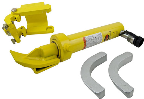 Therefore, it is necessary to check its electrical adjustment.
c) Checking the electrical adjustment of the relay-regulator. They check with a measuring device - an ampervoltmeter or a DC voltmeter with measurement limits of 0-12 V. The purpose of this test is to determine whether the generator generates current, what voltage and how the voltage regulator regulates this current. Therefore, during the test, the generator current is measured, namely at terminal 61 of the main terminal block. The battery is disconnected from the electrical system. The check should be carried out by two people: one serves the motorcycle and changes the engine speed if necessary, the second measures the electrical parameters. During the measurement process, it is also necessary to monitor the engine crankshaft speed, on which the generator power and the operation of the relay regulator depend. nine0005
It is much easier to determine the speed with a tachometer. The motorcycle is placed on a stand, and the engine is pu-.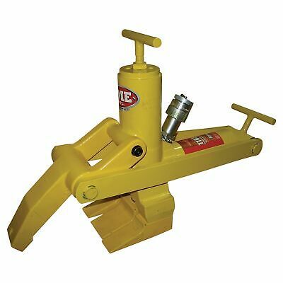 Ekayut, not including transmission. The crankshaft speed is measured with a tachometer. If there is no tachometer, then after starting the engine, turn on the fourth gear, the wheel will rotate, as when driving. The engine speed is determined by the speed that the speedometer shows. The dependence of the motorcycle speed on the engine crankshaft speed is known (Fig. 194).
169
Measurement sequence. The motorcycle is put on a stand and the engine is started. The key is in the "Ignition on" position. The right engine crankcase cover has been removed. First, the closing voltage of the reverse current relay is measured. A voltmeter PV is connected (Fig. 195) to measure the closing voltage of the relay in parallel with the generator. The output wire is connected to the ground of the generator, and the second one is connected to terminal D of the relay-regulator or to terminal 61 on the generator terminal board. The engine runs at a low crankshaft speed, which gradually increases after connecting the measuring instruments.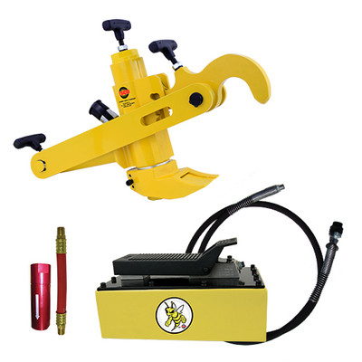 At a voltage of 6.2 to 6.6 V, the electromagnet of the relay-regulator will attract the armature, and contacts X1 and X2 will close. If the relay does not turn on when the voltage is within the specified limits, then it must be adjusted as described below. nine0005
The voltage maintained by the voltage regulator is checked both in the absence of load in the electrical system and at rated load. First, they check the voltage without load in the electrical system: from terminal B of the relay regulator (which means from terminal 51 of the main terminal panel of the generator), when the engine is running, the wire coming from the battery is disconnected, and a measuring device is connected to it, and the positive pole of the battery is connected to mass of the generator armature. The alternator armature speed increases so much that the voltage at the meter no longer increases. The voltage measured in this case must not exceed the permissible value (8 V). The voltage regulator operates at the second stage of regulation.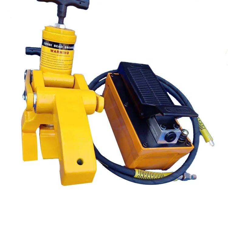 Then they gradually reduce the frequency of rotation of the generator armature and at the same time monitor when the voltage regulator goes to work on the first stage of regulation. The device will show low voltage. This value is counted again. It must not be lower than 7 V. The difference between the two measured values is called the "junction voltage". Therefore, it is the difference between the voltage at the second and first stages of regulation. nine0005
The transition voltage must be positive. This means that its value, measured at the second stage of regulation, must be greater than at the first stage. At the transition voltage, the armature of the relay-regulator should not oscillate continuously, but should be in a position corresponding to the first or second stage of regulation. Otherwise, the junction voltage difference will be zero or negative.
Load voltage is measured in the same way. To terminal B (see fig. 195) relay-regulator, i.e. to terminal 51 of the main terminal panel of the generator, reconnect the wire from the battery. Then all current consumers are turned on, i.e. headlight, position and parking lights. The current consumed by these devices is 6.7 A; voltage about 6.8V (power about 45.5W). The nut on the lower end of the flat spring of the relay-regulator is installed so that the measuring device at the first stage of regulation shows a voltage of 6.8-7 V. Then, the wire coming from the battery is disconnected from terminal 51 and the voltage is again checked at both stages of regulation, as already has been described. nine0005
170
Reverse current is the current that, with a large drop in the generator rotor speed, goes from the battery to terminal 51 of the relay-regulator and through closed contacts XI and X2 of the reverse current relay to the yoke, i.e. in the opposite direction compared to the current passing in the circuit when the battery is being charged. The current should not exceed 5 A so that the battery does not drain too much. But it should be sufficient for the formation of a large magnetic field strength of the relay-regulator coil with reverse polarity compared to the magnetic field at normal generator power. The resulting magnetic field contributes to the reverse movement of the armature and the opening of contacts XI and X2 of the reverse current relay. This prevents further discharge of the battery. nine0005
An ammeter with zero in the middle of the scale is required for measurement. It is connected in series instead of the removed fuse. The device will show both charging and reverse current, and therefore it does not matter which and where the wire is connected instead of the fuse. It is also possible to connect this ammeter in series with the circuit near the generator so that the electrical system fuse does not need to be removed. Then disconnect the wire from terminal 51 on the main terminal board and connect the wire from the ammeter instead. The other output of the device is connected to the disconnected wire. Then the fuel supply is reduced, the engine crankshaft speed decreases, and the charging current also decreases, which is determined on the scale of the device. At the moment when the generator voltage drops below the battery voltage, the instrument needle will move to zero and immediately deviate to the opposite side of the scale. This deflection is only momentary and is caused, of course, by a reverse current that begins to flow in the opposite direction because the battery voltage becomes higher than the alternator voltage. Its value is determined at the moment of deviation of the arrow of the device, which quickly returns back. Under the influence of the magnetic field of the reverse current, the armature returns to its original position, the contacts XI and X2 of the reverse current relay open, and the reverse current from the battery does not pass. The strength of the reverse current, determined by the measuring device at the moment the pointer is deflected, must not exceed 5 A.
d) Precise mechanical adjustment of the relay-regulator. If during measurements the relay regulator does not provide the prescribed electrical parameters, then it should be checked in detail and, if necessary, mechanically adjusted. Remove the generator stator (after disconnecting the wires at the terminals of the main panel and removing the grids). Then the relay-regulator has free access from all sides. Mechanical adjustment is controlled at two extreme positions of the armature of the relay-regulator: no load, i.e. in a completely free state, and when the anchor is pressed against the end of the coil until it stops. Gaps (Fig. 196) are measured with flat probes.
171
In the first case (Fig. 196, a) the gap between the armature and the end of the coil should be equal to 2.4
mm. If this gap is not maintained, it can be set by bending or bending the armature stop on which it rests upper part in the unloaded state. The stop is formed by a stamped continuation of the contact holder. If both upper screws are removed, which fasten the contact holder and a flat suspension spring with gaskets to the yoke of the relay-regulator, then the holder can be removed and the stop bent as necessary. After bending, the gap between the armature and the end of the coil is again checked, and we must not forget that each change in the position of the holder, its removal and reinstallation affect the correct position of the contact X5 of the voltage regulator. This must be taken into account when reinstalling the holder. nine0005
The gap between contacts XI and X2 of the reverse current relay with an unloaded armature must be within 0.25-0.35 mm. This clearance can be measured with a feeler gauge. If it does not correspond to this value, then it should be installed. Two screws are unscrewed, with which the bakelite base is attached from below to the yoke of the relay-regulator. Under it is a countersunk screw, which clamps the figured pad of the movable spring contact of the reverse current relay. The screw is released, the pad is released, and the contact can be moved to the required distance. After adjustment, the screw is tightened again, while the contact is fixed in the desired position and the bakelite base is installed. If the distance between the contacts of the reverse current relay in the free state is too large, then you can also carefully file that end of the spring with the contact with which it rests on the armature arm. The distance between the contacts of the reverse current relay is in principle only measured and adjusted if the armature is correctly mechanically adjusted in the free state and fully tightened. nine0005
The distance between contact X4 on the flat spring of the relay-regulator and contact X5 of the second stage of regulation with an unloaded armature should be 0.18-0.25 mm. If it does not correspond to the specified value, then it can be easily adjusted by moving the contact holder (after loosening both screws in the upper part).
Measure the amount of movement of the armature control arm from its position when the contacts of the reverse current relay are closed to the position at which the contacts X3 to X4 have just opened (first stage of regulation). This movement is measured with flat probes inserted between the end of the spring contact holder of the reverse current relay and the internal (lower) armature control arm when the armature occupies a position corresponding to the opening of contacts X3 and X4 of the voltage regulator. This is the same situation in which0005
172
the glass ball inserted into the pin on the control arm rests against the adjusting screw of the voltage regulator flat spring. However, the contact of these two parts is not visible from the outside, since it occurs inside the side bakelite plate of the regulator yoke.
It is equally necessary to pay attention to the mechanical adjustment of the relay-regulator at the moment when the armature is pressed against the end of the electromagnet until it stops. In this case, check the gap between the armature and the plane of the upper end of the relay-regulator coil (Fig. 196.6). The gap is set by the height of the pin on the lower surface of the anchor and should be equal to 0.18-0.25 mm. It usually doesn't get any smaller. It happens much more often, mainly after attempts to carry out mechanical adjustment, that this distance exceeds the indicated value. This is caused by the fact that the other armature armature is pressed against the regulator yoke until it stops, and therefore the upper arm cannot approach the end of the coil. Then loosen both screws on the upper side of the contact holder and move the armature of the relay-regulator away from its yoke. nine0005
The next dimension - the gap between the armature control arm and the inner side of the relay-regulator yoke - is interconnected with the previous gap. It is understood that the anchor is fully, all the way, pressed, as it should be in this measurement. In this case, a uniform gap is formed between the planes of the yoke and the control arm of the anchor, equal to 0.18-0.25 mm. And, finally, the last parameter related to the number of mechanical parameters for adjusting the relay regulator. When the armature is pressed all the way to the end of the coil, the spring of the relay-regulator, through contact X4, comes into contact with contact X5 of the second stage of regulation, and even slightly presses it outward from the relay-regulator. This is because contact X5 is on a flat spring holder. When the armature rests against the end of the coil, the end of the holder with contact X5 is bent. The amount of elastic deformation should be 0.2 mm. It is adjusted by bending the spring holder with contact X5. nine0005
Very high demands are placed on the mechanical adjustment of the relay controller. It must be remembered that when setting one adjustment parameter of the mechanism, several others may be violated. Therefore, the adjustment of the relay-regulator should only be handled by experienced specialists. As a rule, this work is best done in a specialized electrical workshop. The quality of mechanical adjustment depends only on the qualifications of the worker. In addition to the material on the mechanical adjustment of the voltage regulator and the reverse current relay, we present below the values of the spring forces. nine0005
The spring force of the reverse current relay contacts in the closed state is 3 ± 0.2 N (0.300 + 0.02 kgf), and the force acting on the X3, X4 contacts of the voltage regulator with an unloaded armature is 2-3.5 N ( 0.200-0.350 kgf). These quantities are never, of course, measured, since this is beyond the capabilities of amateur repair practice. They are checked in specialized electrical workshops with the necessary devices.
e) Adjustment of the electrical parameters of the relay-regulator (Fig. 197). Switch-on voltage of the reverse current relay. If you need to adjust the turn-on voltage of the reverse current relay, loosen the two MOH screws on the armature of the relay-regulator, after which you can move the steel plate under them towards the coil. In this case, the switching-on voltage of the reverse current relay when the contacts are closed will be higher (see Fig. 197), since the suspended steel armature spring is bent upwards in a free state. As a result, during the operation of the anchor, a constant preload is created, which is changed when the lining is moved. If it is shifted towards the yoke of the relay-regulator, then its turn-on voltage decreases. When checking the new setting of the reverse current relay switch-on voltage, the two M3 screws on the plate must be properly tightened. nine0005
173
Current regulator voltage and transient. The flat spring of the voltage regulator, on which the double-sided contact X4 is installed at the top (see Fig. 197), is pressed by the lower end of the hex head screw. By tightening or loosening this screw, it is possible to change the preload of the flat spring, and therefore the regulated voltage at terminal X4 in the second stage of regulation. When the screw is tightened, the preload of the spring increases, and therefore, to press it against the X4 contact, more force is required, and thus more voltage in the electromagnet coil. By unscrewing the screw, the spring preload, on the contrary, can be reduced, and the voltage at the second stage of regulation will be lower. nine0005
The voltage at the first stage of regulation is regulated by the second MOH screw on the flat spring of the relay-regulator. It is located under the double-sided contact X4. The screw has no head and is adjusted with a small screwdriver inserted into the slot. A pin with a glass ball at the end, mounted on the control arm of the anchor, rests against the inner end of the screw.
When turning the M3 screw a few turns to the right, therefore, when screwing, the screw is brought closer to the anchor pin. When the anchor is attracted, they touch earlier. Therefore, the voltage at the moment of contact of the parts (contacts X3 and X4 open) will be lower. Similarly, if the adjusting screw is unscrewed, the distance increases, and in order to break contacts X3 and X4, it is required that the armature of the relay-regulator is attracted with great force, i.e. it is necessary to increase the electromagnetic field, and hence the voltage. The transition area is, as already mentioned, the control area between the first and second control steps, i.e. between the opening moment of contacts X3 and X4 and the moment of closing contacts X4 and X5. Obviously, the transition region expands with a decrease in voltage at the beginning of the first stage of regulation and with an increase in voltage at the second stage of regulation, and vice versa. nine0005
Preliminary test to determine whether the battery is charging with an ammeter. For the test in which it is established whether the battery is being charged by current from the generator, use the same ammeter as when measuring the reverse current of the relay-regulator, i. e. with a measurement limit of ± 8 A and zero in the middle. It is connected in series instead of a fuse, and it does not matter which wire it is connected to. While the generator does not produce current at a low armature speed, the electrical system, including the ignition system, is powered by the battery, and the ammeter needle deviates from zero in one direction according to the load. If then the frequency of rotation of the generator armature increases, its power increases, and at the moment the reverse current relay is turned on, the arrow of the device passes through the zero position to the other side of the scale. This means that the generator is producing current,
174
which goes into the battery. The arrow of the device shows the strength of the current, which changes in accordance with the frequency of rotation of the generator armature.
The charging current in amps cannot be precisely determined, it depends on three factors: the rotational speed of the generator armature and thus its power, the load of the electrical system and the charge of the battery. All these conditions can change, so consider the case when the device at an increased frequency of rotation of the generator shaft shows the charging current. Let us indicate the average values: at a high frequency of rotation of the armature without loading the electrical system, the minimum current strength should be 2-3 A, with the high beam headlights on, 1-2 A.
If there is no ammeter with zero in the middle of the scale, then you can use a conventional ammeter with zero at the beginning of the scale. Then it should be connected in series according to the diagram (Fig. 198). With such an ammeter, however, only the charge can be checked, i.e. current in the battery, since a reverse current pulse (before the reverse current relay contacts have time to open) can damage the device. The arrow of the device cannot deviate from zero in the other direction, therefore it is connected only at a high frequency of rotation of the generator armature. nine0005
In view of the change in the strength of the charging current of the battery, the voltage regulator is regulated exclusively using a voltmeter (ampervoltmeter) according to the frequency of rotation of the generator armature and the voltage that the generator creates, and the voltage regulator maintains. of the main panel. nine0005
First measure the power with no load in the electrical system. The current generated by the generator is consumed only by the engine ignition system. At a speed of 35 km / h, the instruments should show approximately the following values: 1-2 A and 6.8-7.2 V. If the speed increases to 90 km / h, then the instruments should show 2-3 A and 7.0 -7.6 V.
If the electrical system includes a load - a headlight lamp (6 V; 25/25 W) and a tail lamp (6 V; 5 W), then at a speed of 35 km / h, the ammeter readings should be near zero at a voltage of 6.2-6.8 V. With an increase in the speed of movement to 90 km / h, the ammeter should show a charging current of 1-2 A at a voltage of 6.6-7.2 V. In this measurement, of course, you should not always remove the fuse and connect an ammeter instead. The measurement can be carried out directly at the generator. Terminal 51 on the main panel is disconnected and the ammeter is connected with one lead to this terminal and the other to the wire disconnected from terminal 51.