If you’ve ever put air in a tire, or checked the air pressure, then you know what a valve stem is. It’s the little tube on your rim that lets you put the air (or nitrogen) in. Inside that tube us the valve, or the actual mechanism that controls the flow of air.
Even though this little component gets used every time you change your tires, get a flat, or check your air pressure, you’ve probably never even thought about changing it. In fact, right now I bet you’re thinking “What’s the difference? It’s not like it’s part of the tire. What could go wrong if I keep using it?”
Well, kind of a lot. You see, as they age, just like any other part of your car, they can begin to break down and develop leaks, which in turn can cause tire problems. Premature or irregular wear and flats or even damage to the TPMS (Tire Pressure Monitoring System) can result from these leaks.
It’s not just age that can cause a valve stem to malfunction, either. UV rays, heat and salt can cause cracks, they can get cut by wheel covers if they’re not replaced properly, and rubbing against curbs or rocks can break or damage them.
Even if it’s a slow leak it’ll mean you’re constantly checking your air pressure and filling up the tire. You may even end up replacing tires you should have gotten more time out of, either because you think they’re the problem or because of damage caused by underinflation! So this seemingly insignificant part can actually end up being pretty costly if it’s not replaced occasionally.
No they are not. A rim with TPMS will have a different stem than a rim without one.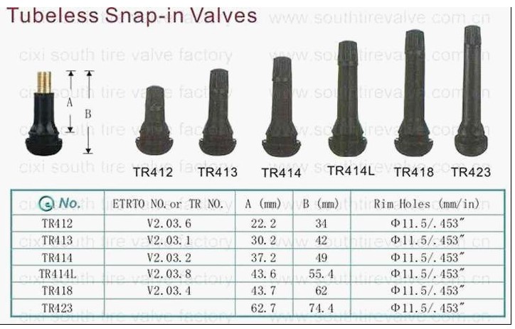 The TPMS ones are usually compatible with the system, either a snap in rubber version or sometimes an aluminum one. But don’t worry, you don’t have to go figuring out what’s the difference, because your mechanic will know which stem is right for your vehicle!
There are also metal and rubber stems. Metal stems aren’t necessarily better than rubber ones, but they are used a lot for appearance. For example, they’ll be a better match with your fancy chrome rims. However, it’s very important to remember that the stem has to be compatible with the valve. Since most metal stems are aluminum, you don’t want to use them with a brass valve! Aluminum and brass together result in a galvanic reaction that leads to corrosion and valve failure. So generally, aluminum stems are used with valves that are nickel plated.
Like I just said, not all stems are the same, and that goes for length as well. Stems come in different sizes to fit different needs. So, if you have wheel covers, you can use a valve stem that lets you check and refill your tire without taking the cover off. Aside from different valve stem lengths, they also make valve stem extenders, so if you’re not ready to change the whole thing you can still adjust the length. However, you have to be careful with these, as they may not seal properly, and that can obviously cause leaks, or worse, let water and dirt get into the core, corroding the valve.
Nitrogen inflation requires better-sealing metal valve caps. These caps are usually silver and usually have a green top with an N or N2 on it (for Nitrogen, obviously). They usually look more like a screw nut than a cap. Since Nitrogen fill is generally pricier than air, you want to make sure it lasts, so it’s a good idea to check these stems regularly. If you do use nitrogen regularly, avoid topping up the tire pressure with regular air. It doesn’t cause any crazy reactions or harm, but it does end up defeating the purpose of using Nitrogen by cancelling out all the advantages.
Valve stems are a crucial part of any tire. Well, they are not part of a tire per se, but they are an auto part designed to ensure the tires’ safety and performance. Therefore, valves are important!
Valves keep air pressure from escaping tires. From valve cores to caps and versatile valve types, we will walk you through everything you need to know about valves and how said valves function.
The small tube system that you can use to fill your tires with air is called a valve stem. This system is basically a one-way door used to transfer gas (in this case air pressure) into a chamber (tire). Different valve types are available.
Valves are located on most pneumatic tires, from automobile to bicycle models. Tire valves are used to add or remove air pressure inside the tire. Once air pressure enters the tire, tire valves do not let it escape on their own.
A tire stem helps tires keep their optimal pressure levels, by using its different components. Valves consist of a valve stem body, a valve core, and a valve stem cap. These work together to keep the correct pressure levels inside the tires.
The various components of valves work together to enable the tire’s secure performance. Air pressure loss can occur if the valves are damaged. But, as long as they properly function, valves will hold air and guarantee the tires’ performance.
There are versatile types of tire valves available for purchase. The type you need greatly depends on various components: mainly what type of tire the valves are used on.
There are three different tire air valve stems manufactured:
These have various applications! Let’s talk about them in more detail.
Probably the most common valve type is the tubeless rubber snap-in tire valve, as they are suitable for passenger cars, light-duty trailers, and various light trucks. Additionally, they can be used in autocross competitions as well.
These tire valves hold a maximum of 65 psi, as a cold tire inflation pressure. This valve stem size usually ranges between 0.7″ to 2.5″ and it can fit 0.453″ or 0.625″ diameter rim holes. Often they sport plastic valve stem covers, but some can be purchased with chrome sleeves or a metal tire pressure cap. However, this is merely for aesthetic purposes.
Check out this valve stem sizes chart:
The tubeless snap-in high-pressure tire valves function in the same manner as the previous type does. However, they are used for applications where the maximum pressure is above 65 psi. In other words, they are for medium- to heavy-duty trucks and trailers, that use pressure to handle larger weights.
These tire valves are made in two rim hole fittings: 0.453″ for tires with a max cold inflation pressure of 80 psi, and 0.625″ for those with 100 psi. Due to the vehicle applications, these valve stem sizes range between 1. 25″ to 2″. High-pressure valve stems are designed for steel wheels. They are equipped with thick rubber snap-in bases, metal barrels, and plastic pressure caps.
Size chart of high-pressure, tubeless snap-in valves:
High-pressure metal valve stems are clamp-in models that use a rubber grommet, which seals the valve against the wheel when you tighten the holding nut. These valves are generally manufactured for high speed, racing vehicles, or for vehicles exceeding 130 mph.
Most metal clamp-in tire valves are available for 0.453″ and 0.625″ rim holes. However, some special applications are available for 0.236″ and 0.315″ rim holes. Additionally, they come in straight or bent styles to accommodate even unique wheel shapes. These valves hold maximum cold tire inflation of 200 psi.
These valves have two fitting types: with the retaining (holding) nut inside or outside of the rim. For aesthetic reasons, many drivers prefer it to be hidden inside the rim. However, outer placements allow you to tighten the nut whenever it is necessary.
We have talked about the types of tire valves you can purchase for different vehicles. Now, let’s see their components.
Like most auto parts, valves also consist of multiple parts, which are:
These individual parts of valves work together to hold air in the tires. Some are crucial and some don’t have to be used. However, these parts working together will guarantee the vehicle’s secure drive.
A valve cap should be used on all valve stems. There is a good reason for this! Moisture contamination and loss of air pressure at high speeds can cause problems. They can damage the valve core or cause the tire to do flat. However, a valve cap will help prevent these issues.
Tire valve caps are available to be manufactured from plastic, metal, or metal with a special screwdriver design. When these caps are used greatly depends on which vehicle they are on. When it comes to everyday driving, a plastic tire pressure valve cap should be enough. However, for racecar applications, a metal one is better. Tire stem caps are either knurled or hexagon-shaped to make them easier to remove.
While missing tire valve covers are not the end of the world, it is advisable to replace them. For one, it is a second seal that prevents pressure from escaping, in case valve core damage occurs. On the other hand, it also makes sure that sand, dirt, and moisture does not enter the stem and damage it.
A valve core is the main seal inside the stem. This part of the stem seals tire pressure inside the tire, preventing it from escaping. It should be tightly screwed into the valve core chamber. They are manufactured with shorter (for high speed applications) and longer lengths, and nickel-plated and brass valve cores are available.
It is important that you only use a nickel-plated valve core with an aluminum tire pressure sensor valve stem. This is due to brass valve cores in such applications experiencing corrosion that can transfer and affect the aluminum wheel as well. This is to protect the wheel and its integrity.
These valve cores basically consist of a spring-loaded pin that is moveable. This allows air pressure to inflate and deflate the tires. This valve stem seal prevents pressurized air from escaping the tires when the caps are off. The valve stem core is durable, but dirt, moisture, and sand can damage it. Dirt and sand will prevent valve cores from sealing properly, while moisture will freeze and damage the valve cores.
If you fit wheel covers on your car, you can use valve extensions to make the inflation process easier. These nylon or metal extenders are available in sizes between 0.5″ and 2″.
It is important to select the ideal extension length or to purchase durable, preferably metal, ones. Road and weather conditions and driving habits can easily damage these extensions, which will leave to other issues.
If your vehicle uses direct TPMS sensors, then the valve stems also hold the sensor inside the tire. Mechanics do this with metal clamp-in or rubber snap-in valves. These TPMS sensor tire valve stems work together to transmit information to the TPMS monitor.
The two different TPMS stem types function a bit differently. Let’s see how!
A clamp-in valve stem-sensor combination fits the sensor with a rubber seal and a retaining. These two parts, along with the valve cores and caps, need to be tightened correctly, in order to prevent pressure loss.
These TPMS rubber valves need nickel-plated valve cores to prevent damage. Galvanic corrosion can damage brass cores, which will transfer onto the aluminum barrel with time – leading to even bigger damage.
The other type of TPMS sensor tubeless tire valve is the rubber snap-in version. These accept TPMS sensors can be different, and purchasing valve stems that accommodate them in crucial.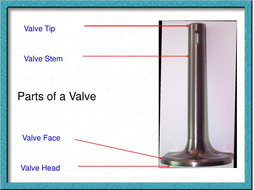
If the TPMS stems are not compatible, it will lead to air pressure loss. Using the correct combination of valves and TPMS sensors will ensure a safer driving experience.
Have you ever noticed a vehicle with green valve stem caps?
Well, there is a reason for their distinct color! These valve stem seals keep the pressure inside of nitrogen-filled tires. Many believe that adding nitrogen in tires improves their performance, durability, fuel economy, etc.
Therefore, nitrogen valve stem caps are green!
Are Valve Stems Replaced with New Tires?
Usually, when mounting new tires on a vehicle, it is advisable to get new valve stems for tires as well. However, when you purchase new tires, the tire valve stem is not included.
The valve stem sizes you need depend on the rim size. Low-profile rims (up to 0.9″) will need a 1.5″ stem while a 1. 3-1.7″ rim should have a 2.3″ valve stem. Anything taller than 1.9″ needs at least a 3.1″ valve stem to properly function.
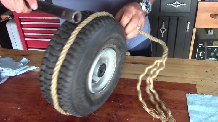
To find a slow leak in a tire, you will needs a spray bottle and soapy water. Mix liquid soap and water in a spray bottle and spray the entire tire (sidewalls, tread area, along the rim, and the valve stem). The slow leak will be there the soapy water forms small bubbles with the escaping air.
Air pressure escapes the tire when the valves are open because of the different pressure levels inside the tire and in the atmosphere. The high pressure of the tire flows out until the tire features the atmospheric pressure. This causes the tire to go flat.
The main difference between the intake valve and the exhaust valve is the diameter of the plate: the intake valve has a larger one. Why? Because the suction of air from the atmosphere into the cylinder under the action of vacuum occurs at a lower speed than pushing it out of the cylinder by the piston.
It's simple: the amount of air (or air-fuel mixture) is the same, but the speed is different. Accordingly, where the speed is lower, the hole is wider, and the plate covering it is larger in diameter. nine0003
All this is true for those valve mechanisms, where the intake and exhaust valves are equal in number - one or two each. However, there are engines with an odd number of valves: two intake + one exhaust or three intake + two exhaust. Everything is the opposite here: the diameter of the exhaust valve plates will be larger than that of the intake ones, because the manufacturer compensated for the low suction rate by adding one “extra” hole, and not by increasing the diameter. You can read more about the ratio of valves and cylinders in the corresponding article. nine0003
The second important difference in valve design is their operating temperature. Inlet valves operate at 350-500 degrees, but exhaust valves are harder - hot exhaust gases heat them up to 700-900 degrees. Therefore, accordingly, exhaust valves are often made more heat resistant.
The heads (or poppets) of the inlet and outlet valves can be either the same diameter or different. (on obsolete cars with small valve overlap) - my comment. Typically, the intake valve head is made larger in diameter to improve cylinder filling. For example, the dimensions of the valves of the GAZ-53A car engine: the diameter of the intake valve head is 47 mm, and the exhaust valve is 36 mm. In the KamAZ-740 diesel engine, the diameter of the intake valve plate is 51 mm, and the exhaust valve is 46 mm. Large inlet, small outlet. nine0003
Exhaust valve - a timing element, when opened, exhaust gases are removed (released) from the engine combustion chamber. The release of gases occurs when the piston in the engine cylinder moves from bottom dead center (BDC) to top dead center (TDC). During engine operation, exhaust valves are subjected to significant thermal loads, as they are constantly in contact with hot exhaust gases. The valve head during the operation of the internal combustion engine can be heated within 600-800 degrees. nine0003
After the end of the intake and compression stroke, the main requirement at the time of ignition of the fuel in the combustion chamber is maximum tightness. Inlet and outlet valves are closed. When the piston has taken on the energy of the expanding gases after the ignition of the fuel-air mixture, these exhaust gases must be removed from the combustion chamber. Sealing the chamber at this stage is no longer needed. For the removal of exhaust gases in the design of the gas distribution mechanism, the exhaust poppet valve, which is located in the cylinder head (cylinder head), is responsible. nine0003
On the intake stroke, a vacuum is created, and on the exhaust stroke, increased pressure is formed in the working combustion chamber of the engine. After the combustion of the mixture of fuel and air, the exhaust gases leave the combustion chamber through the exhaust valve that opens at the right time. The force of pressure allows gases to easily exit the working chamber. This explains the smaller size of the exhaust valve head compared to the intake valve head. On the intake stroke, the negative pressure is less than the pressure on the outlet. Exhaust gases are practically pushed out through the open exhaust valve. nine0003
Effective sealing of the combustion chamber became possible due to the use of poppet valves in the timing design of modern internal combustion engines. The valve device is simple, the element has a plate and a stem. The chamfer smoothly transitions into the stem, which makes the valve sufficiently durable. The conical shape of the transition significantly reduces the resistance of the exhaust gases when leaving the chamber, and further improves sealing.
The opening of the exhaust valve is due to the force received from the camshaft cam. The valve stem (stem) is located in the valve guide, which is pressed into the cylinder head. The camshaft cam presses directly on the valve stem or rocker, from which the force is transmitted to the rod. The valve seat is also located in the cylinder head. The valve seat is a recess that is shaped to match the top of the valve disc. The valve disc and valve seat are pressed against each other with filigree precision. This solution ensures maximum tightness at the moment when the inlet and outlet valves are closed. The main task is to exclude the breakthrough of gases from the combustion chamber. nine0003
A special undercut is made on the upper part of the valve stem. The specified groove is the installation site of the "cracker". This "cracker" is a conical ring, which is cut into two equal parts. The solution is necessary for fixing the valve spring disc. If the opening of the valve is carried out due to a “push” from the camshaft cam, then the closing of the valve is realized through the force of the valve spring. The specified spring closes the valve, tightly pressing the plate to the seat. Additionally, there is a mechanism that rotates the valve. This is necessary for uniform wear of the valve and cleaning the valve from carbon deposits. nine0003
The exhaust valve operates under extremely difficult conditions. Exhaust gases cause severe corrosion of the exhaust valves. If the fuel does not burn completely in the chamber, then this can lead to valve burnout. Adjustment of the valve mechanism is an important procedure during the operation of the internal combustion engine. Closing the exhaust valve too early can cause it to burn out quickly.
During the operation of any internal combustion engine, the valve disc and seat are covered with soot. It is almost impossible to avoid soot on valves. The presence of soot causes constant overheating of the exhaust valve. Sooner or later, the valve bearing surface begins to burn out, which leads to loss of tightness in the combustion chamber. The result is a progressive loss of ICE power, difficult starting, etc. nine0003
Microcracks on the valve disc that appeared from overheating gradually increase, as hot gases under pressure begin to break out of the combustion chamber. The valve head under such conditions is deformed and then destroyed. Valve failure actually means the complete loss of functionality by the engine cylinder. After replacement, it is necessary to grind the valve to the seat for the most accurate fit. Ignoring the procedure or poor quality valve grinding will lead to a quick failure of the new valve. nine0003
It is clear that overheating is a serious exhaust valve problem. The exhaust valve is made of special chromium-nickel-molybdenum steel. The basis is nickel, which increases the resistance of the exhaust valve to mechanical destruction. Valve steel has a high heat resistance.
The next step in reducing the thermal loading of the exhaust valve is its design, which is different from the design of the intake valves. nine0003
Exhaust valve stem hollow, cavity filled with sodium metal. Sodium melts and flows inside the valve stem, which improves heat transfer and evenly distributes heat.
TheExhaust Valve can also be provided with additional protection which can greatly extend the life of the element. The only drawback can be considered the final rise in the cost of production of the part.
Among the most common methods of protection noted:
nine0044 Plasma-powder surfacing is considered one of the most economically and practically justified solutions. For such surfacing, various metal powders are used, which are based on cobalt or nickel. Coating technologies are different, but the main task of each of these methods is to fuse a thin layer of protection on the valve surface to increase wear resistance, resistance to corrosion processes and mechanical destruction. nine0003
The intake valve is an element of the gas distribution mechanism of the internal combustion engine, which is responsible for passing the fuel-air mixture or only air into the working combustion chamber (for diesel internal combustion engines or engines with direct injection). The timing inlet valve opens access to the engine cylinder, and then blocks access before the moment when the compression stroke begins.
The inlet valves are made of special steel. There are separate requirements for such steel for the manufacture of internal combustion engine valves:
Additional requirements for valve steel require no hardening effect when the valve cools down after high temperature operation.![]() This means that when cooled, the steel should not become brittle. None of the steel grades developed today meet these requirements 100%. nine0003
This means that when cooled, the steel should not become brittle. None of the steel grades developed today meet these requirements 100%. nine0003
ICE valves are made of high-alloyed silchromes, which allows the specified part to work in conditions of the highest heating. This approach provided the required strength of the valve, as well as the ability of the element to resist corrosion processes that actively progress in its operating environment at high temperatures of about 600 - 800 °C.
Valves are placed at a certain angle (30-45 degrees) with respect to the vertical axis. The difference between the intake valve and the exhaust valve is that its plate has a larger diameter compared to the exhaust valve plate. This difference is due to the fact that the moment of opening the intake valve occurs exactly when a vacuum appears in the combustion chamber. At the moment of release, there is an increase in pressure in the cylinder. nine0003
The vacuum in the cylinder at the inlet is inferior to the pressure in force on the exhaust stroke. For the highest quality and complete filling of the working fuel-air mixture at the inlet, valves with a higher throughput are needed. This capacity is realized by increasing the diameter of the intake valve disc or the number of intake valves.
The intake valve disc is flat on the combustion chamber side and conical on the camshaft side. This cone is also called a chamfer. At the moment of closing the intake valve, the chamfer is adjacent to the valve seat, which is also a tapered hole in the cylinder head. nine0003
Precision seating of the intake valve is ensured by the use of a guide bush. The valve stem is inserted into the specified bushing, and the bushing itself is called the valve guide. The valve guides are pressed into the cylinder head housing and additionally fixed with a retaining ring.
Modern power units tend to increase the number of intake valves per cylinder to improve throughput, increase the efficiency of filling the cylinder with a working air-fuel mixture, and improve the power and other characteristics of the internal combustion engine. nine0003
Valve receives internal and external springs. These coil springs are fixed on the valve stem. The opening of the intake valve on the intake stroke becomes possible due to the fact that the force from the camshaft cam is transmitted to the rocker (pusher). The design of modern internal combustion engines implies direct action of the camshaft cam on the valve. The valve springs tightly close (press) the valve back after the rocker runs off the pushrod or the valve stem stops making contact with the camshaft lobe. nine0003
Between the camshaft (its cam) and the valve stem (its end part) there is a structural clearance. Such a gap (may be at the level of 0.3-0.05 mm) was created to compensate for the thermal expansion of the intake valve.
The opening and closing of the intake valves at a well-defined moment is made possible by the angular position of the camshaft, which exactly coincides with the same position of the crankshaft of the internal combustion engine.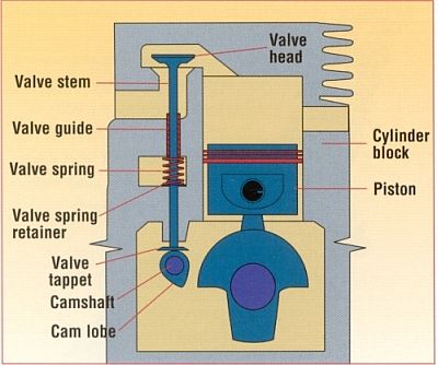 It turns out that the position of the camshaft at the moment of opening the intake valves strictly corresponds to the position of the crankshaft. Engine designs may vary, the number of camshafts may vary. nine0003
The intake valve begins to open slightly before the moment when the piston is at TDC (highest dead center). This means that at the very beginning of the intake stroke (when the piston starts to move down), the intake valve is already slightly open. This solution is called valve opening advance. Different models of power units have different lead, and the oscillation range is in the range from 5 to 30 degrees.
The intake valve closes with a slight delay. The valve closes at the moment when the piston in the cylinder is at bottom dead center and then the upward movement begins. The cylinder continues to fill even after the piston starts to move upwards. This phenomenon occurs as a result of inertial movement in the intake manifold. nine0003
The main malfunctions that are directly related to the internal combustion engine valves are: valve bending, valve overgrowth with soot and valve burnout. Valve bending most often occurs due to a broken timing belt. No less often, the valve bends and when the marks are incorrectly set during the replacement of the timing belt. It is necessary to change the timing belt and put marks on the camshaft and crankshaft pulleys with increased attention.
The malfunction of the valve mechanism is the formation of carbon deposits on the intake and exhaust valves, which manifests itself in increased noise during operation and a drop in the power of the internal combustion engine. Characteristic is the appearance of a metallic knock in the area of the valve cover on the cylinder head, as well as problems with valves are detected by pops in the intake and exhaust manifolds. nine0003
Carbon deposits on valves and seats do not allow the elements to fit snugly together, which leads to a loss of the required compression ratio in the engine. A decrease in compression means a loss of ICE power. Strong soot also leads to overheating and burnout of the valve.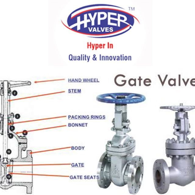
Malfunction of the valve springs can lead to deformation of the cylinder head and sticking of the rod in the valve guide. Incorrect thermal gap between the lever and the rod leads to a strong knock of the valves. In this case, it is necessary to immediately engage in setting the thermal gap required by the manufacturer. Motorists call this procedure valve adjustment. It is necessary to adjust the valves with a certain frequency during the operation of the motor, and also if the indicated possibility to adjust the engine valves was initially provided by the design. nine0003
The intake valve of the timing mechanism opens access to the air-fuel mixture cylinder and stops access before the start of the compression stroke. In the case of a diesel engine, the valve allows only air to enter the combustion chamber.
When the timing belt breaks, the intake valves "hang" as the camshaft stops rotating. Poppets of valves that are open hit the surface of the cylinder
Valves are located at an angle of 30 to 45 degrees from the vertical axis. The intake valve plate is larger than that of the exhaust valve. The difference is due to the fact that at the moment of opening the intake valve, a vacuum is formed in the combustion chamber, and at the moment of exhaust - increased pressure. The vacuum force is lower than the pressure force, so the intake requires valves with a larger head surface to ensure the passage of the required volume of the fuel-air mixture. nine0003
The valve consists of a poppet and a stem. The intake valve plate, which is flat on the side of the combustion chamber, has a conical shape on the side of the camshaft (chamfer). When fully closed, it fits snugly against the "seat" (tapered hole) in the cylinder head. The exact fit of the intake valve is ensured by the guide sleeve, in which the valve stem moves. It is pressed into the cylinder head housing and fixed with a retaining ring. nine0003
The current trend in timing design is to increase the number of intake valves per cylinder. This allows you to increase the capacity of the cylinder and increase the power of the engine
The intake valve has inner and outer coil springs that are mounted on the valve stem.
The intake valve is actuated by a lever (rocker) from the camshaft cam, or, in most modern engines, directly by cam pressure. The spring keeps the intake valve stem in constant contact with the end of the rocker or cam. nine0003
A gap is structurally laid between the camshaft cam and the end of the valve stem. This makes it possible to compensate for the thermal expansion of the intake valve. The value of such a gap is 0.3-0.05 mm.
Timely opening and closing of the intake valve ensures the angular position of the camshaft is precisely synchronized with the same angular position of the crankshaft. That is, the angular position of one strictly corresponds to a certain angular position of the other. nine0003
Depending on the engine model, there may be several intake valves per cylinder.

To radically change the timing of the valves, you need to purchase a set of sports camshafts
Before the piston reaches top dead center, the intake valve begins to open - that is, during the intake stroke, by the time the piston moves down, the valve is already ajar. For different engine models, there is a valve opening advance. The fluctuation limits are 5-30 degrees. nine0003
But the intake valve closes with some delay after the piston reaches bottom dead center and starts moving up. The filling of the cylinder continues even after the start of the movement. This is due to inertia in the intake manifold.
By far, the most common valve failure must be recognized as their bending as a result of a broken timing belt. The same thing can happen without a break if the belt was replaced by a non-professional who mistakenly put marks on the crankshaft and camshaft (or camshaft) pulleys. Breaks are especially dangerous for modern complex engines equipped with variable valve timing and other high-tech systems. nine0003
Another common malfunction of the valve mechanism is the overgrowth of intake and exhaust valves with soot. As a rule, a problem can be identified at a fairly early stage by a decrease in power and pops in the intake and exhaust pipes, metal knocking in the cylinder head and a drop in engine power.
Carbon buildup on seats and valves prevents them from sealing and reduces compression. As a result, the engine power is also reduced. Broken springs can cause the valve to loosen from the seat and lead to deformation of the cylinder head, pitting, or sticking of the stem. A large thermal gap between the lever and the valve stem also leads to a sharp metallic knock and a drop in engine power. nine0003
The intake valves are made of chromium steel, which is resistant to corrosion in gas environments at temperatures above 550 °C. This type of steel is quite fragile.
Automotive engine intake and exhaust valves are poppet-shaped. The valve opens under the action of a valve mechanism controlled by an eccentric cam. The operation of the cam is synchronized with the position of the piston and the period of rotation of the crankshaft. nine0003
As a result, they are made of more resistant materials than inlet valves and therefore more expensive.
The valve guide is positioned coaxially with the valve seat so that a tight, gas-tight contact is made between the valve face and the seat. The valve face and seat are bevelled at an angle of 30° or 45°. These are the nominal values of the chamfer angle. The actual values may differ by one or two degrees from the nominal values. The valves and valve seats used in most engines have a nominal chamfer angle of 45°. The valve is pressed against the seat under the action of a spring. The spring is held on the valve stem (some auto mechanics call it the valve stem) by the spring seat, which, in turn, is locked on the valve stem by a lock (crackers). To dismantle the valve, it is necessary to compress the spring and remove the crackers.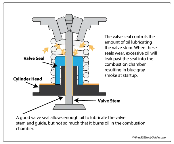 After that, you can remove the spring, cuff, and remove the valve from the head. nine0003
Extensive testing has shown that there are optimal relationships between different valve geometries. In engines with cylinder bores between 3" and 8" (80 mm to 200 mm), the optimum head diameter for the intake valve is approximately 45% of the cylinder bore. The optimum exhaust valve head diameter is approximately 38% of the cylinder bore. The inlet valve must be larger than the outlet valve in order to pass the same mass of gas. The larger inlet valve controls the low velocity rarefied gas flow. At the same time, the exhaust valve controls the high-speed compressed gas flow. A smaller valve can handle this flow. As a result, the exhaust valve head diameter is approximately 85% of the intake valve head diameter. For normal operation, the valve head diameter should be approximately 115% of the valve window diameter. The valve must be large enough to cover the window. The valve lift above the seat is approximately 25% of the head diameter. nine0003
Automotive valve heads (often referred to as poppets by auto mechanics) come in a variety of designs, either rigid or flexible. The rigid head has high strength, shape retention and high thermal conductivity. It also has higher wear resistance. The elastic head, in turn, is able to adapt to the shape of the saddle. Therefore, the elastic valve reliably seals the window, but overheats, and bends when seated in the saddle, when the valve adapts to its shape, can lead to its destruction. In the design of valves, a head is widely used, above the front surface of which a small cap protrudes. Such a valve has a fairly light weight, high strength and heat transfer, and a slightly higher price. Elastic heads are more common on intake valves, while hard heads are more common on exhaust valves. nine0003
Cold air entering hot exhaust valves immediately after the engine has stopped can cause serious damage to the valves. Engines equipped with exhaust manifold heads and/or in-line mufflers allow cold air direct access to the exhaust valves. Rapid cooling may cause warping and/or cracking of the valve. In cold windy weather, when the wind blows cold outside air directly into the exhaust system, such conditions are not uncommon. Counterflow mufflers with long exhaust pipes and an exhaust gas catalytic converter reduce the risk of such a situation. nine0003
Alloys used in automobile exhaust valves consist mainly of chromium, which provides high heat resistance, with small additions of nickel, manganese and nitrogen compounds. If it is required to give the valve special characteristics, then it is subjected to heat treatment. If the design of the valve from a homogeneous material cannot provide the necessary strength and heat resistance, then it is made welded - from two different materials. After processing, the junction of the parts of the valve cannot be distinguished. The valve heads are made of special alloys, which are heat resistant, tough, corrosion resistant, lead oxide resistant and high hardness.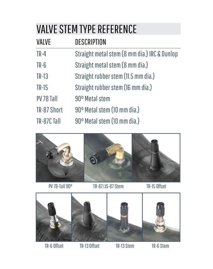 The heads are welded to rods made of materials with high wear resistance. In heavy-duty valves, stellite-type carbide materials are sent to the head face and the top of the car intake valve stem. Stellite is an alloy of nickel, chromium and tungsten and is non-magnetic. In cases where it is necessary to increase corrosion resistance, the valve is aluminized. Aluminizing the working bevel reduces wear when using unleaded gasoline. An aluminum oxide film is formed on the surface of the valve, which prevents welding of the steel chamfer of the valve to the cast iron seat. nine0003
Some types of heavy duty engines use sodium metal hollow stem exhaust valves. Sodium, when the valve is heated to operating temperature, melts, turning into a liquid. This melt splashes in the stem channel and removes heat from the valve head to the stem. The heat is then transferred through the valve guide and absorbed by the cooling system. The monolithic design of the intake and exhaust valve, with the right choice of materials, generally ensures good performance in automotive engines. nine0003
The valve is pressed against the seat with a working chamfer, hermetically closing the combustion chamber. The seat is usually formed as a structural element in a cast iron cylinder head - such a seat is called an integral seat. Seats are usually induction hardened to allow unleaded gasoline to be used. This ensures that seat wear is slowed down during engine operation. In the process of seat wear, the valve sinks deeper into it - it sinks. In cases where corrosion and wear resistance must be particularly high, plug-in seats are always used. In aluminum heads, the seats and valve guides are plug-in only. It should be noted that the operating temperature of the exhaust valve seats in aluminum heads is 180°F (100°C) lower than in cast iron heads. Insert seats are used as a life-saving measure when rebuilding badly damaged inline valve seats. nine0003
Seat distortion is the leading cause of premature valve failure. Valve seat deformation can be reversible - as a result of exposure to high temperature and pressure, or irreversible - as a result of internal mechanical stresses. Mechanical stress is a force acting on a body that tends to change its shape.
Engine valves
The purpose of the valve is to open or close the intake or exhaust port located in the cylinder head (overhead valve mechanism) or in the cylinder block (lower valve mechanism). The main parts of the valve are the head and the stem. nine0003
The valve must securely isolate the cylinder during the compression and power strokes from the inlet or outlet pipeline and in the open position, provide as little resistance as possible to the movement of gases. Smooth transition from the valve head to its stem: reduces resistance when gases flow around the valve.
The valve, like other parts of the gas distribution mechanism (rod and pusher), must be light so that large inertia forces do not arise during its reciprocating motion. nine0003
To ensure that the valve fits snugly on the seat, the underside of the valve head is chamfered at a 45° angle (rarely at an angle of 30°), which is ground.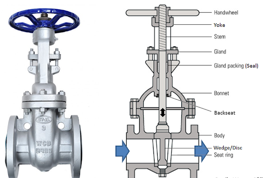
The most commonly used valves in automotive engines are flat or tulip heads. Flat head valves are lighter and have a smaller heating surface. nine0003
Good gas flow is achieved with a tulip-shaped head, which has a very smooth transition from head to stem. This is especially important for intake valves, which are often made with a tulip-shaped head (M-21, GAZ-13 engines), which ensures the best filling of the cylinder with a combustible mixture.
Inlet and outlet valve heads can be the same or different diameters. Typically, the intake valve head is made larger in diameter to improve cylinder filling. The diameter of the inlet valve head is limited by the size and design of the combustion chamber, as well as the diameter of the exhaust valve, which must result in sufficiently complete cleaning of the cylinder. An example is the valve dimensions of the FA3-53A engine, which has an intake valve head diameter of 47 mm and an exhaust valve diameter of 36 mm. The YaMZ-236 engine has an intake valve diameter of 61. 5 mm, and an exhaust valve diameter of 48 mm. nine0003
Fig. 1. Valves:
a - with a flat head; b - with a tulip-shaped head; 1 - valve head; 2 - rod
Sometimes a slot is made into the valve head, used to lap the valve against the seat.
When the engine is running, the temperature of the exhaust valve reaches 800-900 °C, and the intake valve 300-400 °C, since it is periodically cooled during intake strokes by a relatively cold charge of a combustible mixture or air. The valves are exposed to high temperatures and the corrosive effects of gases. Therefore, the material used for their manufacture should not deteriorate the mechanical properties at high temperature and should resist corrosion and abrasion well. Alloy steel satisfies these requirements. Due to the fact that the exhaust valves are exposed to a higher temperature than the intake valves, heat-resistant chromium-silicon steel (sil-chromium) is used for their manufacture. Inlet valves are made of chromium-nickel steel.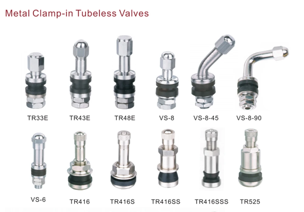 nine0003
Diesel valves YaAZ-M204 and YaAZ-M206 consist of two welded parts: a chromium-nickel steel stem and a head made of heat-resistant steel.
If the valves have heads of the same diameter, then marks are knocked out on them, for example, VP (inlet) and EP (outlet).
Exhaust gases cause corrosion and increased wear of the exhaust valve seats, so they are made of special heat-resistant cast iron inserts.
If the engine has a gas distribution mechanism with overhead valves and a cylinder head cast from an aluminum alloy, then seats made of heat-resistant cast iron are pressed into the cylinder head under all valves (engines M-21, GAZ-53A, ZIL-130). nine0003
The valve stem moves in a guide sleeve made of cast iron and pressed into the cylinder block (GAZ-51A engine) or into the cylinder head (M-21, GAZ-53A, ZIL-130 engines, etc.). The sleeve ensures that the valve fits on the seat without distortion.
In M-21, GAZ-53A and ZIL-130 engines, guide bushings are made of cermet, i. e. a pressed and sintered powder consisting of copper, graphite and iron. Ceramic-metal bushings have good anti-friction properties. On the outer surface of the bushing, a groove is made for the retaining ring, which keeps it from possible axial displacement. nine0003
Fig. 2. The rotation mechanism of the exhaust valve of the ZIL-130 engine:
1 - exhaust valve; 2 - mechanism body; 3 - ball; 4 - support washer; 5 - key ring; 6 - valve spring; 7 - spring plate; 8 - cracker; U - disc spring; 10 - return spring; 11 - metallic sodium; 12 - guide sleeve; 13 - valve seat; 14 - heat-resistant surfacing; 15 - plug; 16 - cylinder head
At the end of the valve stem there is a groove for connecting it to the spring using crackers and a plate. The valve spring ensures a tight fit of the valve on the seat and presses the pusher against the camshaft cam during engine operation. The spring is constantly in a compressed state: one end of it rests against the support washer, and the other end against the plate put on the valve stem (M-21, GAZ-BZA and ZIL-130 engines).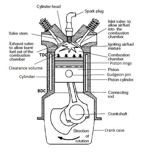 Spring 6 has a constant coil pitch. nine0003
Sometimes not one spring is placed on the valve, but two with different winding directions so that the springs do not jam. In the presence of two springs, their length decreases and the reliability of the valve operation increases, since if one spring breaks, the valve will be held by the other (MZMA-408, ZIL-111 and YAME-236 engines).
The GAZ-51A lower-valve engine has a variable-pitch spring that prevents valve vibration at high crankshaft speeds. The smaller pitch end of the spring should face the cylinder head. nine0003
A conical sleeve is inserted into the connection of the valve with the spring with the help of crackers and a plate, which tightly covers the crackers. The plate rests on the end of the conical bushing, and the spring rests against the plate flange. This connection of the valve to the spring reduces the friction between them and allows the valve to rotate while the engine is running. As a result, the service life of the valve, its seat and guide sleeve is significantly increased, since one-sided wear of these parts is reduced. nine0003
A cap made of oil-resistant rubber is put on the valve stem, which eliminates oil leakage (during intake strokes) into the engine cylinder through the gap between the valve stem and the bushing. Such caps are not installed on a lower-valve engine, since the valve stem is in different conditions with regard to lubrication and the probability of oil leaking into the cylinder is very small.
The exhaust valve of the ZIL-130 engine has a heat-resistant surfacing on the seating chamfer on the head, despite the fact that the valve is made of heat-resistant steel. A blind hole was drilled in the exhaust valve stem, filled by about one third with metallic sodium (ZIL-130 and TA3-53A engines) and closed from below with a plug. During engine operation, the sodium in the rod melts (the melting point of sodium is 98 °C) and turns into a liquid. As the valve moves back and forth in the guide bushing, the sodium moves around the head and removes heat from it to the stem.
The exhaust valve of the ZIL-130 engine during operation is forcibly rotated by a special mechanism, the body of which is placed in the socket of the cylinder head.
Housing 2 has five sloping recesses for balls with return springs. A disk spring and a support washer are put on the upper part of the body with a gap. The valve spring rests on the plate at one end, and on the support washer at the other. nine0003
When the valve is closed, the spring force is transmitted through the washer to a disk spring, under which there are five balls. The inner edge of the disc spring rests on the case shoulders, and the valve spring acts on its outer edge. When the valve is opened, the spring is compressed, and the force transmitted to the support washer and disc spring increases. As a result of this, the disk spring straightens and a gap appears between its inner edge and the case shoulders. After straightening the disc spring, the force of the two springs is transferred to the balls. The balls, rolling over the sloping recesses of the body, compress the return springs and at the same time (due to the presence of friction) rotate the disk spring together with the support washer, which in turn causes the valve spring to rotate simultaneously with the valve.