Calculate Out-The-Door Price
close
× ‹
All fields are required
Submodel
Select TPMS OptionTPMSTPMS: NOTPMS: YES
WHAT IS TPMS?Enter Zip Code WHY DO WE ASK ABOUT YOUR ZIPCODE?
ZIP code is needed for local pricing.">Why?
Cross Section
Aspect Ratio
Rim Diameter
Enter Zip Code Why?
7980 S Broadway
Littleton, CO
303.515.7308
Most stores are open nights and weekends
Directions
Store Hours:
| Day(s) | Hours |
|---|---|
| MON-FRI: | 7:00am-7:00pm |
| SAT: | 7:00am-6:00pm |
| SUN: | 9:00am-5:00pm |
Store Details Change Store Find a Store
Schedule An AppointmentLearn more about Oil Changes
7980 S Broadway
Littleton, CO
303. 515.7308
Most stores are open nights and weekends
Directions
Store Hours:
| Day(s) | Hours |
|---|---|
| MON-FRI: | 7:00am-7:00pm |
| SAT: | 7:00am-6:00pm |
| SUN: | 9:00am-5:00pm |
Store Details Change Store Find a Store
Schedule An AppointmentLearn more about Brake Service
All fields are required
Engine
Enter Zip Code Why?
All fields are required
Submodel
Enter Zip Code Why?
FIRESTONE HAS BEEN THE NATION'S LEADING TIRE PROVIDER FOR MORE THAN A CENTURY.
It's a tough road out there, and your tires bear the brunt of potholes, broken glass, nails, screws, and anything else that can puncture a tire. Firestone Complete Auto Care's flat tire repair services are the best in the business. We've been repairing tires since 1926, and we take pride in repairing America's tires. When tire damage strikes, come to Firestone Complete Auto Care–the tire repair shop you can trust.
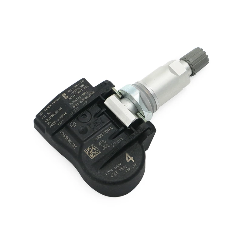
If you suspect something is wrong with your vehicle's tires, don't hesitate to come into a Firestone Complete Auto Care near you. If your Tire Pressure Monitoring System (TPMS) light is on, you've hit something on the road, your tire is losing air, or maybe something just doesn't feel quite right, bring it in. One of our expert technicians will take a look and tell you if you need to repair or replace your tires.
Driving on a damaged tire can lead to additional (and more costly) rim damage and repairs, so it's best to have your tires examined at the first sign of trouble. The solution might be as simple as needing one of our patch plugs if the tire puncture is addressed early on. In other cases, a leaking valve stem or valve core may need to be replaced with a new one or the TPMS sensor needs to be reprogrammed or replaced. Visit your nearest Firestone Complete Auto Care, and we'll take care of you and your vehicle tire repairs.
Schedule An appointment
Tire Repair & Patching/Plug
If your tires still have life left in their tread and are not over 10 years old, Firestone Complete Auto Care maybe be able repair or patch & plug them to get you back on the road quickly. Keep in mind not all tire damage can be patched if the puncture is too big.
Tire Replacement
Over time, the tread on your tires wears down, leading to compromised traction on the road and potentially dangerous driving conditions. Tires generally need to be replaced every 25,000 to 50,000 miles, depending on vehicle manufacturer recommendations and driving habits.
Tire Rotations & Balancing
When you have your tires rotated, you help increase the life of your tires by helping reduce uneven wear. Most vehicle manufacturers recommend a tire rotation about every 5,000 miles or at the manufacturer-recommended mileage. Tire balancing helps ensure weight is evenly distributed around your tires. It's necessary about every 5,000 miles or as recommended by your manufacturer. Balancing can lead to a smoother ride, less tire wear, and reduced strain on the drivetrain. When you think tire balancing, think safe, smooth, and efficient driving.
Wheel Alignments
It's best to have your alignment checked every 6,000 miles or twice a year. Even one misaligned wheel can cause the steering wheel to be off center and can lead to premature wear and tear on your vehicle over time. Keeping everything properly aligned ensures a smoother ride for you and a longer life for your tires.
Flat Repair
A flat or leaking tire can leave you stranded on the side of the road or lead to a situation where you lose control while driving. Take care of flat or leaking tires as early as possible to extend tire lifespan and ensure your tire doesn't leave you stranded.
Schedule An Appointment
All fields are required
Engine
Zip Code Entry Why?
Flat tires rarely happen at ideal times. Let Firestone Complete Auto Care help you with these answers to frequently asked flat tire questions.
To ensure a safe drive that doesn’t damage your rims or create more expensive repairs, change your flat tire with your spare tire before coming into your local Firestone Complete Auto Care center for flat tire repair.
It’s tempting to replace just the tire that's damaged, but replacing one tire at a time can present challenges down the road since the one tire will have a different tread depth and thus different accelerating, braking, and cornering abilities than all of the others.
Few things are more inconvenient than a flat tire —except back-to-back flat tires. Learn the reasons why you keep getting flat tires and what you can do to help prevent flat tires from deflating your spirits!
If your vehicle hits a pothole in the road, you may experience steering and suspension system misalignment and/or damage, tire punctures, bent rims, and more. When your vehicle experiences a sudden jolt from a pothole run-in, timely inspection is highly recommended.
Pothole damage may not be obvious right away, but it can wreak havoc on your entire car if it’s not addressed quickly and fixed right the first time. If you've had a recent run-in with a pothole, head to your local Firestone Complete Auto Care for a Complete Vehicle Inspection to check for any issues.
A tire plug is a quick fix for a tire that's leaking air from a nail or similar object that has punctured the tire. A tire plug fills the hole of the tire but is not reliable without a tire patch and not recommended to use alone. A patch is applied to the inside of the tire to further prevent an air leak and helps hold the plug in place. This allows a tire with ample useful life left in it to hold air reliably and keep you on the road for longer.
Run flat tires allow you to drive on a flat tire for a limited time with lesser risk than non-run flat tires. A Run Flat tire could be repaired if a nail or object is caught before tire damage occurs. However, if the tire is permanently damaged, it is required to replace a Run Flat tire with a new one.
The Tire Pressure Monitoring System light will illuminate if tire pressure is too low or part of the TPMS system has malfunctioned. Important TPMS warning light behavior:
Looking for the closest flat tire repair shop? Come to Firestone Complete Auto Care for a tire plug & patch or other tire repair service today!
Read More
Regular tire rotations can help prevent uneven tread wear and help your tires last longer. Schedule a tire rotation appointment at a Firestone Complete Auto Care near you today.
Read More
Knowing when to replace tires is as easy as measuring tire tread depth. Learn more about this important measurement and visit Firestone Complete Auto Care!
Read More
Tires
Aug 19, 2022
What are the symptoms of unbalanced tires, and do yours need balancing? Learn everything you need to know about this often-overlooked aspect of car maintenance.
Read More
Tires
May 20, 2022
Trying to decide between conventional and Run-Flat tires? Learn how Run-Flats work and how they differ from regular tires to see which may be better for you.
Read More
Tires
Dec 3, 2021
As temperatures dip and snow creeps into the forecast, you may be wondering, “Can I drive with all-season tires in winter?” Here’s what you need to know.
Read More
LOAD 3 MORE
SHOWING 6 OF 12
View More Articles
{{storeNumber}}
{{storeName}}
{{link-icon "Call Us" mobileCallLink null "call-cta"}} {{link-icon "Directions" directions "_blank" "directions-cta"}}
{{address}}
{{city}}, {{state}} {{zip}}
{{#if activeFlag}} {{#ifCond mystore "or" myPreferredStore}} {{#ifCond storeType 'eq' "TPL"}}
*Call store for appointment {{phone}}
{{else}} {{#if onlineAppointmentActiveFlag }}
{{#if myPreferredStore}}
{{else}}
*Call store for appointment {{phone}}
{{/if}} {{/ifCond}} {{else}} {{#ifCond storeType 'eq' "TPL"}}
*Call store for appointment {{phone}}
{{else}}
Schedule Appointment {{#if onlineAppointmentActiveFlag}} {{else}}
*Call store for appointment {{phone}}
{{/if}}
{{/ifCond}} {{/ifCond}} {{else}}
*Temporarily Closed Due To: {{temporarilyClosedReason}}
{{/if}} {{#if isMilitaryStore}}
*This location is on an active US military base. You may need military ID to access the location.
{{/if}}
{{#ifCond count 'eq' "3"}} Show More Stores {{/ifCond}}
Your browser's Javascript functionality is turned off. Please turn it on so that you can experience the full capabilities of this site.
{{address1}}{{#rating}}
{{#rating.starClasses}}
{{/rating.starClasses}}
{{rating.value}} ({{rating. number}})
{{/rating}}
{{#isAppointmentEnabled}}
{{/isAppointmentEnabled}}
We know what to do to fix tires the first time, every time. After all, your safety rides on your tires being in good condition.
If your flat tire is repairable, we’ll fix it for free on most non-commercial passenger cars and light trucks.
We’ll get your tires repaired as fast as possible. Just come by any Les Schwab location or make an appointment online.
Every year, we mend more than 1 million tires. We guarantee that each repair will last the life of the tire.
The Best Tire Value Promise® Limited Warranty is provided for free as part of Les Schwab’s World Class Customer Service and is valid for the original purchaser of the new passenger and tubeless light truck tires listed on the original invoice (“Covered Tire(s)”).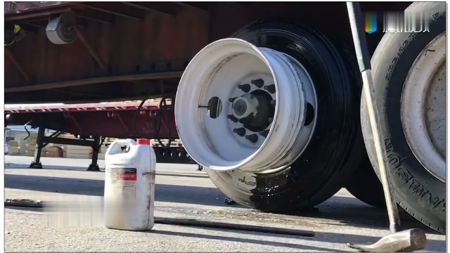
Whatever the road throws at you, from potholes to nails or other road hazards, you have peace of mind protection that we will repair or replace your Covered Tire for its remaining value under the terms of this Best Tire Value Promise® Limited Warranty. Our workmanship is guaranteed for the life of your Covered Tires.
Les Schwab provides tire protection for Covered Tires with non-repairable damage due to normal road hazards (“Tire Protection”). If a Covered Tire is eligible for Tire Protection, you are entitled to one of the exclusive remedies listed below. Normal road hazards are unexpected contact of a Covered Tire with objects on the road that are not a normal part of the road surface, such as rocks, nails, potholes, unexpected debris, or glass
EXCLUSIVE REMEDIES: If a Covered Tire is eligible for Tire Protection, fails to conform to the limited warranty for tread life, or fails due to defects in manufacture or materials, Les Schwab will provide at its election one of the following exclusive remedies:
A. If a Covered Tire eligible for Tire Protection incurs non-repairable damage during the first 25% of tread wear, Les Schwab will replace it free of charge. After the first 25% of tread wear, Les Schwab will provide a pro-rata adjustment consistent with section (C).
B. If a Covered Tire wears to a tread depth of 2/32nds before the mileage indicated in the limited warranty for tread life, Les Schwab will make a pro-rata adjustment based on the original purchase price, excluding Federal Excise Tax, multiplied by the pro-rata adjustment. The pro-rata adjustment is 100% less miles of service divided by the mileage indicated in the limited warranty for tread life.
C. If a Covered Tire fails due to defects in its manufacture or materials during the first 25% of tread wear, Les Schwab will replace it free of charge. After the first 25% of tread wear, Les Schwab will make a pro-rata adjustment based on the original purchase price, excluding Federal Excise Tax, multiplied by the pro-rata adjustment. The pro-rata adjustment is the percentage of remaining tread down to 2/32nds. Except as set forth in section (B), a tire worn down to 2/32nds tread depth is not a Covered Tire.
D. You may elect to receive an adjustment in the form of cash or a credit applied to the purchase of new tires at any Les Schwab Tire Center.
WHAT IS NOT COVERED BY THE LIMITED WARRANTY FOR TREAD LIFE: The limited warranty for tread life does not cover services, damage or wear due to any of the following: misuse or abuse, misalignment or tires out of balance, over or underinflation, repairs, off road use or use on unpaved roads, use on commercial vehicles, campers, or trailers, excessive loading, vehicle accidents, or tire contact with curbs, poles, garbage bins or other similar items on or off the road surface.
All repairable flats on passenger and tubeless light truck tires listed on the original invoice are fixed free of charge for the life of the Covered Tire through 12. 00 inch size cross section. Lock ring and tube type wheels are not included.
Proper flat repair is like a graft. The patching material used gets chemically bonded to the tire tread and is intended to make your tire as good as it was before the flat. It’s no more likely to need repair again than the other tires in your set that haven’t gone flat. The repair will last for the life of the tire but in the unlikely event there is an issue, we will fix it for free.
We use the industry standard approach called plug and patch. We clean up the hole in the tread, get any debris out, plug the puncture with rubber and plies and patch the tire. We also reset the TPMS (tire pressure monitoring system).
From the time the vehicle gets into the repair bay, the work takes 15 to 20 minutes on average. It just depends on the wheel, the size and the tire type. Flat repairs are done first come, first served, so there could be additional time involved if there are others ahead of you.
There could also be more time required if it’s a self-sealing tire or you’ve used an aerosol fix-a-flat kit. Then we have to clean out the sealant gunk and dry the inside of the tire as part of the process. We also clean the TPMS sensors and verify they haven’t been damaged by the spray.
Come by any Les Schwab Tires for free flat tire repair. Find a store.
July 7, 2017
With harness and repair kit.
This method of repairing a tire with a harness is only suitable for tubeless tires! Also, the method is not suitable for repairing punctures on the side surfaces of the tire and punctures with a hole larger than 6 mm.
Find the puncture site and clean it. If a nail or bolt caused the puncture and it is still in the tire, then it must be removed. The puncture site must be marked so as not to look for it again in the future.
Then it is recommended to lower the pressure in the tire to 0.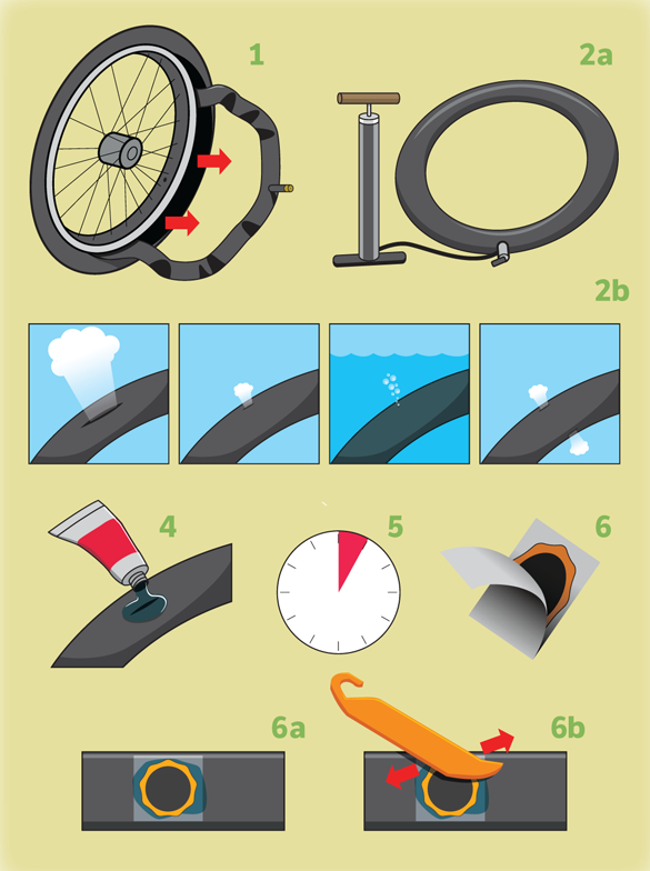 5 atm. This will relieve tension in the tire structure and prevent damage to the cord.
Now you need to insert the tip of the awl-rasp into the puncture hole and increase the diameter of the hole for inserting the tourniquet.
Treat the tourniquet with activator glue and insert it so that both ends stick out, and the rounded middle remains inside. The tourniquet is inserted using an applicator with a head divided into two.
After installing the harness, you need to inflate the tire and check for air leaks. If the air escapes, then the procedure must be repeated. If everything is done correctly, then the bus will not skip.
When the harness is inserted, the tire is inflated and there is no leakage, the protruding ends of the harness are cut off. Any knife will do, a thin clerical knife will do the job well.
Since the harness weighs practically nothing, there is no need to do tire balancing after repair. It remains only to check the pressure in the tires, and you can hit the road!
“I often travel through the private sector, as a result, I periodically visit a tire shop, where for a certain amount of cheaper wooden ones they remove the wheel for me, look for the culprit of the air leak from it, carry out the most difficult and expensive operation to remove it and seal up traces of his presence in the tire.
I decided that in some cases it is possible to avoid this algorithm of actions and correct the situation without visiting a tire fitting - on my own. As an assistant in this matter, I chose the AUTOPROFI REM-30 Master Tubeless Tire Repair Kit - the source of the review.
Repair kit allows you to repair a tubeless tire puncture at any time and continue the trip. If the hole diameter does not exceed 6 mm, you do not need to go to the workshop - you can even fix the situation on the side of the road. The time spent on tire repair, as a rule, does not exceed 10 minutes. The kit includes: awl-rasp, tourniquet applicator, elastic cords (3 pieces), glue.
An indispensable set for all motorists. Allows you to repair a tubeless tire puncture at any time and continue your journey. If the hole diameter does not exceed 6 mm, you do not need to go to the workshop - you can even fix the situation on the side of the road.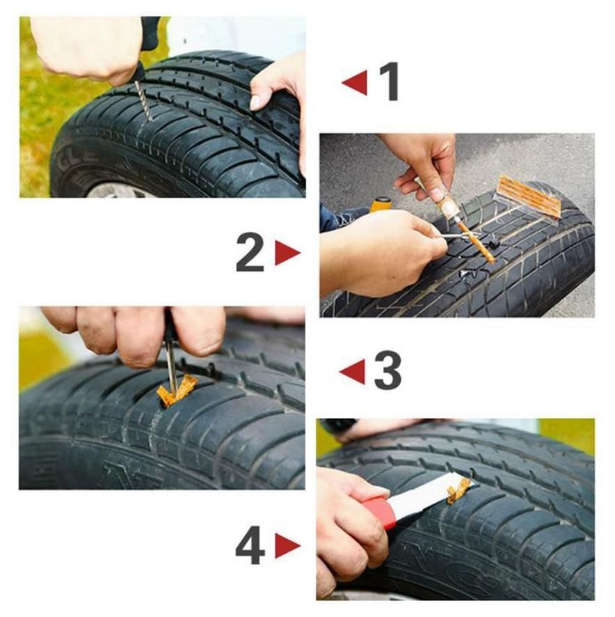 The time spent on tire repair, as a rule, does not exceed 10 minutes. The kit includes: awl-rasp, tourniquet applicator, elastic cords (5 pieces), glue. The handles of the awl and the applicator have a comfortable shape.
The repair kit allows you to repair a tubeless tire puncture at any time and continue your trip. If the hole diameter does not exceed 6 mm, you do not need to go to the workshop - you can even fix the situation on the side of the road. The time spent on tire repair, as a rule, does not exceed 10 minutes. The kit includes: awl-rasp, tourniquet applicator, elastic cords (5 pieces), glue.
An indispensable set for all motorists. Allows you to repair a tubeless tire puncture at any time and continue your journey. If the hole diameter does not exceed 6 mm, you do not need to go to the workshop - you can even fix the situation on the side of the road. The time spent on tire repair, as a rule, does not exceed 10 minutes. The kit includes: awl-rasp, tourniquet applicator, elastic cords (5 pieces), glue. The handles of the awl and the applicator have a comfortable shape.
Separately, you can purchase a set of harnesses (50 pieces per pack) and an activator adhesive (packing of 2 tubes).
Recently, a friend of mine, who began to be interested in electronics and circuitry, asked me to give him some practical advice on the development of electronic devices. At first, this question puzzled me a little: somehow it happened that for myself I never singled out any lists of mandatory design rules, I had all this somewhere at the subconscious level. But this question served as a good impetus to sit down and formulate at least a small list of such recommendations. When everything was ready, I thought that maybe it would be interesting for someone else to read, and thus this article came about.
The article is a list of ten basic design rules that are relevant in the development of a wide class of devices. In the article, I deliberately do not touch on the issues related to the design of printed circuit boards - this is a topic for a separate discussion. The rules are given in random order without any sorting by alphabet, significance, frequency of use in practice, etc. This list of rules also does not claim to be complete and absolute truth, it contains my experience in developing electronic devices and nothing more.
The presence of power capacitors is a necessary condition for the normal operation of any microcircuit. The fact is that they provide a pulsed current that the microcircuit consumes when switching internal transistors. If there is no capacitor in the immediate vicinity of the microcircuit, then due to the inductance of the tracks of the printed circuit board, the current front can be swamped, and the required rate of its rise will not be provided. It may well be that the microcircuit will not work at all, such cases occur. Due to this feature, capacitors with low ESR and ESL (Equivalent Series Resistance and Equivalent Series Inductance) should be selected. In the vast majority of cases, ceramic capacitors perform well, and if a large capacity is suddenly required, tantalum ones.
The number of capacitors for each microcircuit must be at least the number of power pins for this microcircuit. That is, if a microcircuit has 10 power pins, then at least 10 capacitors must be installed on only one of this microcircuit, and these capacitors should be placed on the printed circuit board as close as possible to the power pins. Often, manufacturers recommend installing another additional capacitor of a larger rating common to all power outputs of the microcircuit. The figure below shows an example from the documentation for the super-popular STM32F103 microcontroller: as you can see, in addition to 5 0.1 uF capacitors at the VDD pins, the manufacturer also recommends installing one common 4. 7 uF capacitor.
The choice of capacitor capacitance deserves special attention. In most cases, you will not go wrong if you choose a capacitance of 0.1uF. However, do not be too lazy to look at this issue in the documentation for the microcircuit: there may also be subtleties here. For example, RF ICs often require a smaller capacitor. Below is a picture from the documentation for the LT5560 mixer chip. As can be seen from the figure, the manufacturer advises the use of 1 uF and 1 nF capacitors.
Deviations are also possible in the other direction: for example, the 4G module WP7502 requires the installation of a capacitor of as much as 1500 uF near the power pins:
In general, it is better to always specify the values of the required capacitors in the documentation for a particular chip.
Unfortunately, it is not so rare to find circuits where a resistor in a 0402 case is in a 220 V circuit or something similar.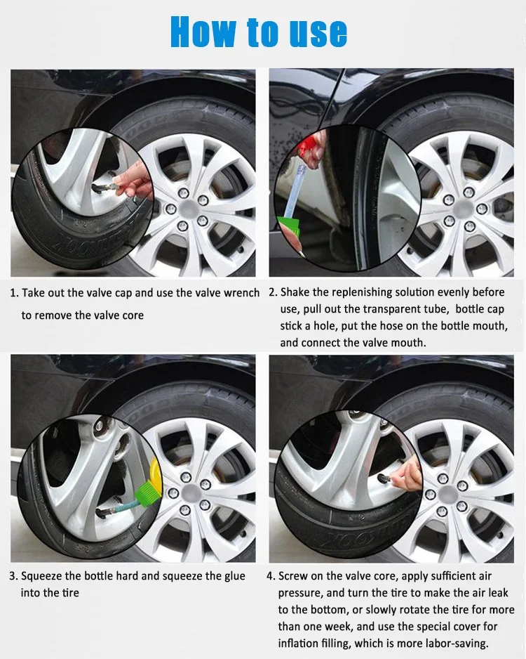 You can't do that! Before installing any (absolutely any) component on the circuit, you must make sure that under no circumstances are the maximum allowable current, voltage and power dissipation parameters for this component exceeded. All calculations must be made for the worst operating conditions (in particular, for the maximum possible voltage on the circuit), and see the limiting parameters in the documentation for a particular component.
Consider a simple resistor example. Suppose we have calculated the circuit and we need to provide a resistance of 25 kOhm, and the maximum allowable voltage in this circuit is 100 V. What resistor will we put in the circuit? We open the documentation for Bourns RC series resistors and see the main limit parameters:
In circuits with a voltage of 100 V, resistors of the CR0805 or CR1206 series can work. CR0603 can not be put there. What about power dissipation? As the school physics course says, for a DC circuit it is calculated by the formula:
None of the resistors presented in the table can withstand such power, however, we can connect several of them in parallel: 4 pieces of CR0805 or 2 pieces of CR1206. Just do not forget that when resistors are connected in parallel, their equivalent resistance decreases. For example, we can take 4 pcs. CR0805-JW-104ELF (100 kΩ): By connecting them in parallel, we get exactly 25 kΩ. For critical applications, you can further reduce the load on each of the resistors by connecting in parallel not 4 pieces, but 6 pieces.
The maximum allowable current for the RC series resistor is 2 A, and it will obviously not be exceeded here, this is easily checked using Ohm's law. Moreover, this parameter is mainly relevant for resistors with low resistance, for the rest you will run into excess power much faster.
How to choose capacitors? After determining the type of capacitor used (ceramics, tantalum, film, electrolyte, etc.), it is necessary to provide a voltage margin of at least 25-30%. If possible, then for responsible applications it is better to take the stock twice. In some cases, in addition to voltage, it is also necessary to take into account the pulsed current through the capacitor. This parameter is very often forgotten, although the current overload of the capacitor in the circuits of some switching power supply will not end in anything good. Consider an example. Let's say we calculated our switching power supply and determined that it is:
The capacitance and voltage of the capacitor are large enough, so the use of an electrolytic capacitor is justified. For example, EEH-ZA capacitors from Panasonic are suitable.
We open documentation on them:
At first glance, it seems that 35 V is more than 30 V, and this capacitor should suit us. However, in this case, the margin will be only 5 V, which is very small. The correct solution is to choose a 50V capacitor.
Looking further, we have a 50V capacitor with a required capacitance of 100uF. It would be possible to take it, but its maximum current is equal to our expected 2 A (for a frequency of 100 kHz), that is, again there will be no margin for this parameter.
Therefore, it would be correct to take two 68 uF 50 V capacitors and connect them in parallel. Thus, we get a total capacitance of 132 microfarads, a maximum voltage of 50 V and a maximum pulse current of 3.6 A. Such a system will be reliable and work for a long time.
Inductors, transistors, and in general any other components are selected in a similar way. You should always remember about their limiting parameters and take components with a margin of at least 25-30%.
The limiting parameters can also include temperature. There are three main temperature groups:
This division is not absolute, there are also all sorts of extended subranges.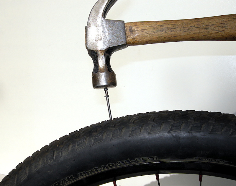 But one thing is important - all (absolutely all) components on your circuit must fall within the temperature range specified by the technical task. That is, when designing a circuit, always keep in mind the required operating temperature range and select components in accordance with it. The operating temperature ranges (as well as the limit temperature ranges) are always given in the documentation.
It's also worth noting that you most likely won't be able to buy Military range chips: they are not sold to everyone.
An electrostatic discharge can burn out the ports of a microchip worth thousands of dollars in a fraction of a second. For this reason, you should always remember it and take measures to protect your devices. In general, the topic of protection against static electricity is quite extensive and in itself deserves a separate article. As part of this, we will try to briefly consider the basic rules that I have developed for myself:
 ), which the user will then contact, must definitely be protected from static electricity.


What exactly should I use as static protection? Now there is quite a wide choice:
Next to such diodes, it is recommended to place a small capacitance connected by power supply.
 Safety first
 The main rule of the doctor - do no harm. The main rule of the developer should be "Create devices that are safe for others." In this section, I'll look at some of the more common hazards:
 Always duplicate such important circuits with some kind of oak logic.
 More detailed information on the topic of safety can be obtained in GOSTs and other standards.
Examples
If you think that the user will not mix up the pinout of your power connector or will not supply 27 V instead of 12 V, then you are mistaken, this will happen sooner or later. This can still be somehow avoided if your equipment is powered through some standard connector, but in any other case, I recommend protecting the input power circuits from user errors. Of course, little will save you from a nuclear explosion or from a direct connection to a 10 kV substation, but there should be basic protection elements. In this article, I will very briefly consider two types of protection: from reverse polarity and from increased input voltage.
There are quite a few circuits for reverse polarity protection, but in my practice I widely use two of them: using a diode and using a field effect transistor.
The reverse polarity protection circuit using a diode is shown in the figure:
The advantage of this circuit is its extreme simplicity, but it has a big drawback: the VD1 diode can get very hot. The power dissipated on it can be roughly estimated by multiplying 0.4 ... 0.8 (voltage drop across an open diode) by the current consumption of the circuit. For an accurate calculation, you can use the CVC of the diode, which is always in the documentation for it. But even so, it is obvious that at a current of 1 A, several tenths of a watt will be released on the diode, which will not only be wasted, but, in the absence of a heat sink, will most likely quickly kill the diode (especially if it is in a small case). Therefore, such a protection scheme can be used only if the current consumed does not exceed units or tens of milliamps.
For more powerful circuits, it is better to use a field-effect transistor protection circuit, it is shown in the figure:
the interested reader will have no problem finding information. Therefore, we will immediately move on to overvoltage protection circuits.
There are at least two approaches to protect against overvoltage: installing some kind of electronic fuses (hotswap, power controllers) at the input of the circuit, or installing voltage limiters. Of course, it is possible to combine these two approaches in one scheme.
Electronic fuse chips come with a variety of functions: they can monitor overvoltage, undervoltage, provide protection for current, temperature, power, provide a smooth increase in current, and much more. An example of a good electronic fuse is the TPS1663 chip, a typical switching circuit of which is shown below:
This chip provides overvoltage protection, but it itself has a maximum allowable voltage of 67 volts. How to protect yourself in this case? Unfortunately, it will not be possible to increase protection indefinitely, and in this case there is only one option left: to allow something cheap to burn in the circuit and break the circuit, saving all the valuable stuffing of the circuit. And here we smoothly move to the voltage limiters.
The voltage limiter can be a varistor, a protective diode (TVS) or even a gas arrester. Talking about the pros and cons of each would be drawn to a separate article, so it will not be considered within the framework of this one.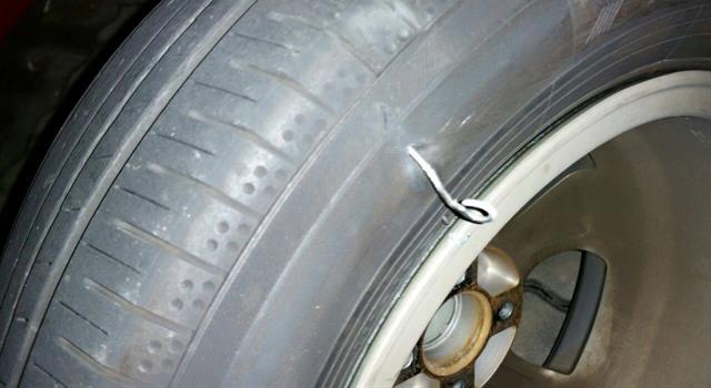 It makes sense to use voltage limiters in conjunction with a fuse: in this approach, a varistor or protective diode limits the voltage by passing a large current through itself, which causes the fuse to burn out and open the circuit. If circumstances are not very successful, the limiter itself may also burn out, however, valuable microcircuits on the board must be saved and, which is also very important, a possible fire is prevented. The simplest device protection circuit using a varistor is shown below:
We have reviewed the main schemes for protecting the board from power reversal and overvoltage. The designer must select the optimal combination of protection schemes based on reliability requirements, user error, PCB space, and product cost. As a conclusion for this section, I will give a fragment of the input stage circuit implemented in one of my latest developments. This circuit provides a full range of protections: FET reverse polarity protection, undervoltage and overvoltage protection, as well as current protection on the TPS1663 chip, and to top it off, protection using a varistor and a fuse.
A very common mistake of novice developers is to draw a diagram, lay out a board (maybe even make it) and only after that think about the device case. And here the most interesting begins: it seems that there is an excellent case for the device on sale, it would practically fit ... if the board were two millimeters shorter. And the next case size is already one and a half times larger, but you have to take it, because the alternative - custom-made case - is too expensive. As a result, we have an unreasonably large body, in which a small printed circuit board dangles. But this could have been avoided if the issue of working out the body of the equipment was not left for later, but decided simultaneously with the development of the printed circuit board.
When a complex device with a custom case is being developed, then high-quality development, in principle, cannot take place without the close collaboration of the designer, circuit engineer and topologist (sometimes, however, this is the same person :)). It is important to understand that this work takes place simultaneously: the circuit engineer draws the circuit and sends it to the topologist, the designer at this time determines the dimensions of the printed circuit boards depending on the design of the product, and also issues all kinds of restrictions on the height of the components and forbidden zones, the topologist makes a preliminary arrangement of the components on the printed circuit board. board and passes it to the designer for integration into a common 3D model, the circuit engineer coordinates everything and, if necessary, responds to wishes like “here it would be nice to pick up a throttle a couple of millimeters lower.”
But a comprehensive design approach is not limited to design.
If the product involves writing embedded software, it is necessary for the circuit engineer to interact with the programmers at the stage of developing the block diagram of the future device. This is necessary both for planning the development time, and for determining the possibility of software implementation of the embedded circuit solutions.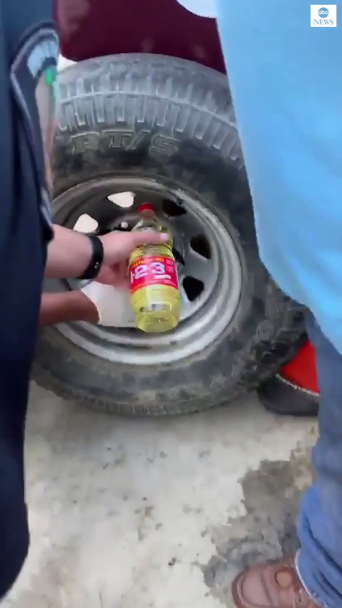 Unfortunately, if the circuit engineer lacks knowledge about the features of software development, some of the solutions embedded in the circuit may turn out to be in principle unfeasible from the point of view of writing software, and all this will become clear only after the manufacture of printed circuit boards. Therefore, in order to avoid such a sad scenario, it is worth considering and agreeing on all issues of principle in terms of software with those who will write this software later.
In addition, when talking about an integrated approach, one cannot fail to mention such an important point as the organization of future production. Already at the stage of drawing a circuit, you need to think about how this board will then be produced, how to debug, check, and test it. Already now it is necessary to lay down control points for measuring the voltage of power supplies, think about jobs, about all kinds of cables and where to connect them, about the verification methodology.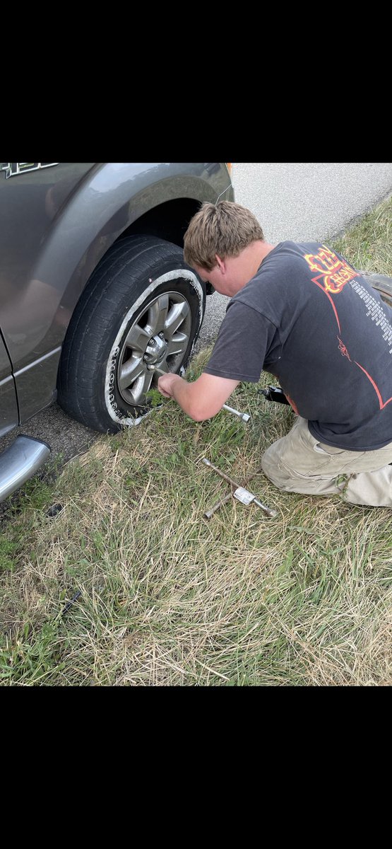 It may very well be that in order to test your board in mass production, you will need special equipment - its development (at least in a sketch form) must be started in parallel with the board being tested, because these are two interconnected devices.
In general, as a short summary of the current section - approach development in a complex way. Think about product design, chassis, software development, how your devices will be manufactured and tested at the very beginning of the design, and not when most of the work has already been done, and any step aside is accompanied by a huge expenditure of resources.
I'm sure that any developer is familiar with this situation: the circuit is designed, the board is wired, the components are soldered, and now the product gets debugged. We turn it on and it doesn't work. We begin to look for the cause - that's bad luck, the RX and TX of the UART are mixed up. Or D+ and D- for USB.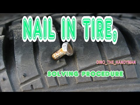 Or MOSI and MISO to SPI. Or ... yes, you can make a mistake anywhere, especially if this piece of the circuit is being done for the first time. You have to take a scalpel, cut the tracks on the printed circuit board, strip the mask and try to solder wires to these very tracks. But what if the tracks are in the inner layers of the printed circuit board? Are the microcircuits in BGA package? Yes, and using Via-In-Pad technology? That's where the real pain is. At such moments, you involuntarily begin to envy programmers whose problem can be solved by recompiling the program, while here the prospect of a complete alteration of the printed circuit board looms without the ability to revive the current one. Is there any way to avoid such a sad ending? Often yes. In the case when some piece of the circuit is being made for the first time, and the topology of the printed circuit board is not conducive to experiments, it is better to connect “doubtful” circuits not directly, but through a zero resistor (resistor with a resistance of 0 Ohm).
In this case, even if you make a mistake in the scheme, the error will not be fatal. It will be enough to remove the soldered resistors and connect the circuit in the right way. It will do without cutting tracks and, moreover, without picking copper on the inner layers of the board.
The question may arise - is it not too wasteful to put resistors on the board like this, which are not really needed? Well, at the time of writing, the price of a DigiKey zero resistor in the 0402 package was about $2 per 1000 pieces. Let everyone decide for himself whether it is expensive or not. In addition, I note that zero resistors are only needed on prototypes, when there is still no confidence in the correctness of the circuit. At the start of mass production, when all the shortcomings of the circuit have been eliminated, it is quite possible to eliminate them in a new revision of the board.
The choice of the type of zero resistor must be approached comprehensively. At least the following parameters must be taken into account:
For example, if you put wirewound resistors in high-speed circuits, the circuit will most likely not work: the parasitic inductance of them is too high. For most digital circuits, SMD resistors work well. I usually use the 0402 package - this is a kind of compromise in terms of PCB space and ease of installation. Zero resistors in the 0402 package do not have a significant effect even on relatively high-frequency circuits: High Speed USB (480 Mbps) and gigabit Ethernet function stably. There were no problems even in the sub-gigahertz range of radio paths: zero resistors happened to be used there as an element of matching. But, of course, when designing a high-frequency circuit, you should always remember about the parasitic parameters of zero resistors (and not only them) and, if necessary, perform simulation.
In practice, there are very often cases when highly sensitive analog paths and noisy digital processors are present on the same printed circuit board. Or powerful switching converters and fault-prone digital control systems. In general, when in the neighborhood on one piece of textolite there is some source of interference and components sensitive to them are located next to it. How to be in this case? Practice says that 90% success in creating such devices is a well-routed printed circuit board. With the correct arrangement of elements, with a competent stack and with the formation of land and food polygons according to certain rules. But the current article is not about printed circuit boards, in addition, one should not underestimate such things as power filtering and land separation, which we will talk about in this section.
The main point of the ground sharing process is to ensure that the return currents of the "noisy" digital or power circuits do not flow together with the return currents of the sensitive circuits: otherwise, the sensitive circuits can pick up noise voltage fluctuations on ground planes and interpret them as part of a useful signal, which will inevitably lead to errors in operation. To do this, two nets with different names are created in the project (for example, A_GND and D_GND). Sensitive ground circuits are connected to A_GND, and "noisy" ones are connected to D_GND. But if digital and analog blocks communicate with each other (and this happens almost always), it is necessary to connect the A_GND and D_GND circuits to each other (otherwise there will be nowhere for the return currents to flow). How to do it right? There are different opinions on this matter. I usually connect these circuits together with a zero resistor, placing it near the power supply on the printed circuit board.
If you are working in Altium Designer, there is a special type of component called Net Tie for this purpose, you can also use it.
Sometimes it is recommended to use an inductor to connect these ground circuits, arguing that it is good at blocking high-frequency noise. But I categorically do not advise you to do this: do not forget that the return signal currents between the digital and analog parts of the circuit will also flow through this inductance. This will lead to severe distortion of the waveform and, possibly, to the complete inoperability of the circuit.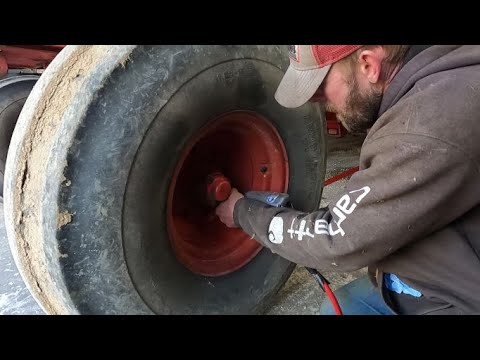 It is useful to use inductors in power circuits to filter it, but this must also be done carefully. Let's look at this issue in a little more detail.
First of all, you need to remember one simple rule: the filter inductance must always be paired with a capacitor. A circuit without a capacitor, most likely, will not work at all. Why? See the first section of this article.
The type and rating of the inductor is selected based on the expected intensity of interference on the power supply, the spectrum of interference and the characteristics of your circuit. Of course, the current margin must be observed. In my practice, for power filtering, I quite often use Murata BLM series inductors: they are designed specifically for filtering noise in equipment of various types. A brief description of the inductances of the BLM series is shown in the figure.
Transients are how the system behaves until a steady state is reached.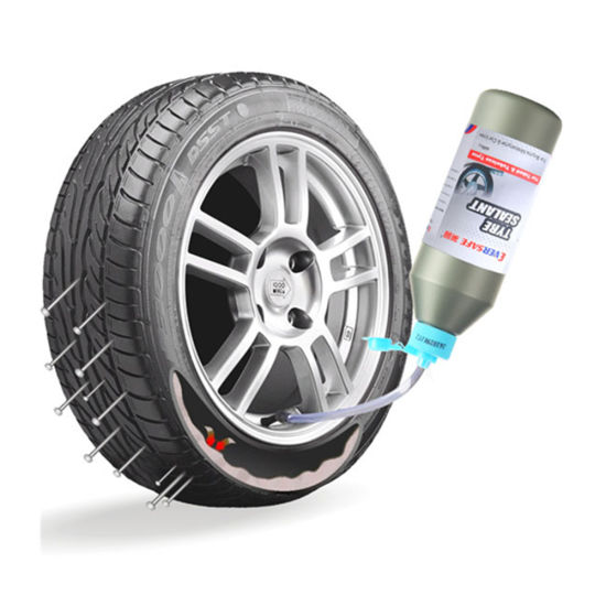 In particular, transient processes can be understood as the moments of power-up, the moments of connection of the load to the source, the switching of keys, and much more. In general, a detailed consideration of transient processes is a topic for a whole series of articles. In this article, we will consider in more detail the issue of turning on the power, as the most common one.
Situation 1. You have wired a board to a laboratory power supply. You apply power and find that your board, instead of starting up, is in a cyclic reboot mode. What is happening and what to do?
Indeed, such situations can arise and the reason is in the transition process. At the time of start, your board can consume several times more current than at the time of regular operation. This is especially noticeable if there is some powerful processor on the board.
The rising current pulse travels from the power supply to the board through wires, which, alas, are far from ideal: they have both parasitic resistance and parasitic inductance. All this leads to a voltage dip on the board: this dip is processed by the processor supervisor and, as a result, we have a cyclic reboot. There are several solutions to the problem: shorten the wires and increase their cross-sectional area, use laboratory power supplies with feedback, or even put a power converter on the board and apply a higher voltage to the board.
Situation 2. You power up your board and then you notice that at the initial moment, for some reason, the LED that should be turned off winks slightly. Or, for a short moment, some kind of power converter starts working, which, it seems, should be blocked in the processor software. Or the relay randomly clicks. What's the matter? An error in the code? Everything can be both simpler and more difficult at the same time. Perhaps you simply did not take into account the state of the I / O ports of the processor (or some other microcircuit) at the moments of reset and initial initialization. Meanwhile, this is an important parameter that should not be forgotten. Usually such moments are registered in the documentation. For example, STMicroelectronics explicitly writes in the documentation for its STM32F750 microcontroller that all pins, except for those responsible for programming and debugging, are configured as inputs during the reset and immediately after it, not pulled up to either power or ground.
What threatens us? A track on a printed circuit board with high-impedance inputs on both sides is an excellent antenna for picking up all sorts of interference. And if it is connected, for example, to the EN input of some power source, or controls a relay, then at the moments of initial loading, this power source can randomly turn on and off, and the relay clicks at insane speed literally at the wave of a hand. Fortunately, this problem is solved quite simply: it is enough to put pull-up resistors to GND or to VCC with a nominal value of 10 ... 100 kOhm on critical circuits. They will reliably fix the signal level at the moments of initialization and will not allow chaotic switching of peripheral devices.
However, it is worth remembering that the state of the microcircuit pins at the moments of reset and initial initialization is very individual and depends on the specific microcircuit. And if in the same STM everything is quite simple and clear, then, for example, in the AM4376 processor from Texas Instruments, everything is much trickier: part of the GPIO has a HIGH-Z state, some have PU pull-ups, others have PDs:
Situation 3. You have completely de-energized your board, but the LED on it is still on, or are the microcircuits showing some activity? What's the matter, is it really a perpetual motion machine? Alas, everything is much simpler. Most likely, you still have some USB-UART converter or other peripherals connected to the board, powered on the side and having a high logic level on their outputs. The fact is that any microcircuit has two diodes at its inputs, connected between GND and VCC. Through these diodes, the voltage from the input of the microcircuit can penetrate the power output of the microcircuit and further spread throughout the board, as shown in the figure.
Of course, it is hardly possible to fully power the entire board in this way. However, some intermediate voltage level can form on the VCC circuit: less than the supply voltage of the microcircuit, but nevertheless sufficient for the microcircuits to be in an “incomprehensible” state. Fortunately, most microcircuits are still not particularly sensitive to such voltage surges, but this problem must not be forgotten, and if necessary, special isolating buffers should be placed in critical circuits.
And now we have the last paragraph of this article.
Carefully. Is always. It really contains answers to most questions, including those that we have considered in this article. Yes, sometimes this documentation contains tens, hundreds or even thousands of pages, but the time spent on studying them at the device design stage will more than pay off during the product launch and debugging.