3WHeeLeR WoRLD > The Goods > Trikesylvania > Mad Scientists Lair > Attempting to build my own CDI box......input?
PDA
View Full Version : Attempting to build my own CDI box......input?
Serious Tim
04-30-2007, 12:27 PM
So.....my YT125 Tri-Moto needs a CDI, and I thought, hell, I'm a decent tech, I should be able to figure this out :)
I've got my CDI box open and managed to scrape all of the silicone goo laced with little rocks away to an almost bare circuit board with components (I figured anyone that wanted to hide the components so well, it's GOT to be simple :) ), and I'm looking at one capacitor, a transistor, a diode, 3 or 4 resistors, and a mylar capacitor. Pretty simple if I can figure out what transistor is used.
My plan is to scrape the remaining junk out, and create a schematic of the CDI and attempt to build it on a small universal circuit board and etch the board traces myself. Couple questions for those of you who might know:
1. I assume that the advance for the timing is automatically controlled by the trigger pulse, and not by this transistor on any sort of curve? It's only four wires.....two ground, charge, and trigger.
2. Is there a universal CDI or a cheap one that will work in place of what I'm trying to do? I just don't want to spend $145 for $2.00 worth of electronics. Aside from which, if I can build it functionally, with experimentation I can make it better :twisted:
dansvan
04-30-2007, 04:15 PM
I've seen guys use Ford Duraspark units on ATV's. If they can use those you should be able to use a chevy ignition module as it's smaller.
dansvan
04-30-2007, 04:16 PM
here.
http://rthompson.us/2007/02/14/how-to-convert-an-atv-to-ford-ignition/
maybe this will help.
Billy Golightly
04-30-2007, 04:39 PM
Interesting stuff! I'll be watching this thread closely.
SYKO
04-30-2007, 04:51 PM
I had a ford coil pack for my coil on my 250r and thats is far as I took it, it made stupid amount of spark, if you can make a universal adjustable cdi unit you just built a better mousetrap my freind.
max
04-30-2007, 04:58 PM
Cant you find a used one? I think you might be in over your head. Ive never heard of anyone rebuilding a CDI. Goodluck if you do.
atckowalski
04-30-2007, 05:32 PM
I was just wondering the same thing. Here is a picture of the cdi off my Klt 200.
200x Basket
04-30-2007, 06:38 PM
ebay is your friend. problem solved
Dirtcrasher
04-30-2007, 06:51 PM
I give him alot of credit for contemplating it.
Anyone who knows electronics (like my brother) finds this a challenge and would love to come up with an easy fix or a way to improve it.
Buy a cheap used one to get running but please continue forwards with the project!!
4cylinders
04-30-2007, 08:43 PM
hey, honda cdi's are real reasonable, get one and wire it into the circuit. early 200x would probably do it.
Serious Tim
04-30-2007, 10:23 PM
I give him alot of credit for contemplating it.
Anyone who knows electronics (like my brother) finds this a challenge and would love to come up with an easy fix or a way to improve it.
Buy a cheap used one to get running but please continue forwards with the project!!
That's exactly what I'm doing :)
But, with the thought that a used one might end up failing me in a most inopportune time at some point, I'm going forward, and here's what I've learned by bouncing ideas off of a couple people at work.
The CDI is nothing more than a switching apparatus. On my simple application, it does nothing with the advance curve. The advance curve is calculated by the stator in the same way that the cam plates inside a distributor change the advance in a car work in conjunction with the vacuum advance.
This being said, the charge side of the capacitor is always going, after viewing the schematics of the trike itself, the main power coming from what I'll refer to as the main power rail, which powers the headlights, etc. IN many such applications, the headlight acts as the voltage regulator of the system (it has in simple circuits in Honda scooters, but not in this case).
Okay, so we've got about 5.86 VDC on the main rail and on the trigger circuit. Good. Now the problem is that in the link that dansvan posted as well as every other thing I've seen online assumes a 12V rail. Since this is 6V, I have to come up with something a bit different.
Enter the GM 4 pin module. It has a trigger voltage of between 5 and 7 volts, around 6 being the optimum (as I read it). Great! So here's the module, a pic I grabbed off the net:
http://www.megamanual.com/module.gif
The four HEI module terminals are labeled W, G, B and C.
W = positive lead (+) from the pickup
G = negative lead (-) from the pickup
C = negative side (-) of the coil
B = positive side (+) of the coil
The base of the module must also go to chassis ground, so that should account for all of the major hookups. The next question is whether it will actually work :)
Next, my plan, while still delving into the remains of my current CDI box, is to hook up the GM module in place of the CDI, and measure the exit voltage and pulse that would energize the coil to see if this actually has the potential of working. My only doubt in this regard is that since CDI relies on capacitance discharge, it would have to energize something I would think, and the GM module is nothing more than a switching diode.....the end result being a direct and applied +6V to the coil, but not at a set stored pulse. The advantage of the release from the capacitor versus regular "line" voltage would be not only in an even discharge but higher amperage (if my thinking's correct).
Serious Tim
04-30-2007, 11:11 PM
Looks like inside this CDI there are:
(2) 100K ohm resistors
(1) 150 ohm resistor
(3) blue-banded diodes marked M1
(1) red-banded diode marked IR
(1) 3 lead transistor, light green in color, no identifying markings, similar to a 2N3903
(1) capacitor, rated at 10 uF @ 16VDC
(1) mylar capacitor of unknown value
(1) tiny PC board, printed by Mitsubishi
Total of (6) wire leads
That's it! Time to hand a part of this off to a friend and resident electronics guru, and in the meantime attempt to create a schematic diagram of the unit. If I have a schematic, I can build them quite easily :)
gravelord
04-30-2007, 11:34 PM
bigger capacitor = more juice, more juice = good ............ no?
resistors usually are to cut power - right ? so, in theory, bigger, im guessing, would restrict rev limit???
dont quote me on any of this, except the capacitor one, that im sure of.. 90 percent... but a friend of mine used to be into electronics and make things - before he died. even built a big old frankenstein sized telas coil that shot lightning bolts :) ... well, no sense in trying to match a identicle to stock one. and honestly, even if you made one chances of it being as reliable as a aftermarket or stock one on the market, are probably not very good. (i take that back, probably wont be as as reliable as stock or the good aftermarket ones) but im all for trying things out, and for people to try to "do it them selfs" even if its just for the hell of it! its probably the first time someone tried to make their own cdi, go for it!!!!!!!
4cylinders
05-01-2007, 12:08 AM
hey, I have a couple yamaha cdi's. what does yours look like?
Serious Tim
05-01-2007, 06:48 AM
It's a small rectangular box, about an inch square by say 2" long, roughly.
Serious Tim
05-01-2007, 06:51 AM
bigger capacitor = more juice, more juice = good ............ no?
resistors usually are to cut power - right ? so, in theory, bigger, im guessing, would restrict rev limit???
dont quote me on any of this, except the capacitor one, that im sure of.. 90 percent... but a friend of mine used to be into electronics and make things - before he died. even built a big old frankenstein sized telas coil that shot lightning bolts :) ... well, no sense in trying to match a identicle to stock one. and honestly, even if you made one chances of it being as reliable as a aftermarket or stock one on the market, are probably not very good. (i take that back, probably wont be as as reliable as stock or the good aftermarket ones) but im all for trying things out, and for people to try to "do it them selfs" even if its just for the hell of it! its probably the first time someone tried to make their own cdi, go for it!!!!!!!
You have to remember that if I use the same components or upgraded versions of them, the only difference is in the sealing and/or insulation. But if I'm able to make a universal CDI, I figure I can build them for about 10 bucks a piece or less. Trust me, there's nothing inside this thing that strikes me as that it's built for endurance with the exception of the goo tar that it's sealed in.
Mosh
05-01-2007, 01:23 PM
isnt the Gm hei module you picture Triggered by 250 millivolt ac voltage?Will the trike pick up coil be roughly the same?It will be interesting to see what happens with that.
Serious Tim
05-04-2007, 11:33 AM
My replacement CDI box should be in within the next day, so the first thing I'm going to do is to plug it in and see if the Tri-Moto fires up :)
Assuming it does, then I go forth with development. The first step is to wire up the GM module. Then, wire up the GM module with a charge capacitor on the trigger input side of the module.
I'll keep everyone posted on my progress :)
Billy Golightly
05-20-2007, 09:58 PM
Hows this workin out for you so far?
damageinc2785
05-28-2007, 11:08 PM
i just bought a 84 200x with a homade cdi box on it
i got it from a aerospace enginer who made his own axle and cdi for it
ill get some pics soon
maggiesboy
06-15-2007, 09:49 AM
this thread is killer.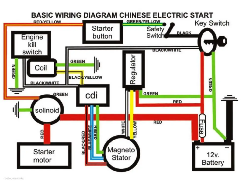 This is the stuff we all lay awake at 3:00AM and think about.
BigRedRunner
06-15-2007, 05:22 PM
How are you going to control the timing curve if you're using an HEI module? HEIs control timing through a mechanical and vacuum curve setup. Are you going to use the remaining guts of the CDI for the timing curve? The only thing variable the module will do is the dwell. Heat sink would be a good idea on that thing too as those modules have trouble if they aren't cool.
TeamGeek6
07-09-2007, 01:04 AM
1.) The CDI can be made with just an SCR and gate trigger circuit. Problem is that knowing whats in the box is not important, knowing what the pulse generator and stator do is.
2.) The box on the first page is NOT a CDI, its a 12 volt breakerless.
3.) It probably cannot be triggered by the stock pulse coil. I tried that with a GM HEI on a 250R, and had to design a signal conditioning circuit - the stock pulser on my 250R wont work.
4.) A bigger CDI capacitor is no good, it must be the proper size. It must be tuned to both the stators ignition windings and ignition coil primary.
5.) " isnt the Gm hei module you picture Triggered by 250 millivolt ac voltage?"
It isnt that simple, the shape of the voltage and current are important.
I may have posted a schematic for PVLs cheap CDI on this BBS somewhere, search for it.
"
(2) 100K ohm resistors
(1) 150 ohm resistor
(3) blue-banded diodes marked M1
(1) red-banded diode marked IR [careful, they may not be ordinary diodes]
(1) 3 lead transistor, light green in color, no identifying markings, similar to a 2N3903 [SCR, not transistor]
(1) capacitor, rated at 10 uF @ 16VDC [low voltage power filter]
(1) mylar capacitor of unknown value [usually o.15uF/300V]
(1) tiny PC board, printed by Mitsubishi [easy]
==========================
"
Enter the GM 4 pin module. It has a trigger voltage of between 5 and 7 volts, "
No.
around 6 being the optimum (as I read it). Great! So here's the module, a pic I grabbed off the net:
The four HEI module terminals are labeled W, G, B and C.
W = positive lead (+) from the pickup
G = negative lead (-) from the pickup
C = negative side (-) of the coil
B = positive side (+) of the coil "
No.
"The base of the module must also go to chassis ground,
No, its not a ground
so that should account for all of the major hookups. The next question is whether it will actually work
yes it will
"Next, my plan, while still delving into the remains of my current CDI box, is to hook up the GM module in place of the CDI, and measure the exit voltage and pulse that would energize the coil to see if this actually has the potential of working. "
Youll need an oscilloscope.
"My only doubt in this regard is that since CDI relies on capacitance discharge, it would have to energize something I would think, and the GM module is nothing more than a switching diode. ...."
...."
There are no switching diodes in that unit. Ive had them apart under a microscope.
"the end result being a direct and applied +6V to the coil, but not at a set stored pulse. "
Huh? The HEI does not put 6 volts on the coil, neither does a CDI on its coil;
The advantage of the release from the capacitor versus regular "line" voltage would be not only in an even discharge but higher amperage (if my thinking's correct)."
Absolutely backwards. 'Amperage" in a CDI is microscopic compared to either these Ford or GM systems.
Louis Mielke
07-09-2007, 05:05 PM
well thank you Mr. Wizard. Maybe you could have formated your post so as to not come off so condescending?
Dirtcrasher
07-09-2007, 07:04 PM
well thank you Mr. Wizard. Maybe you could have formated your post so as to not come off so condescending?
We all have different personalities....
I think GEEK, MYMINT and DR DEATH would all make great buddies. :lol: Maybe we should have an "elite gifted few" forum :w00t:
As for the rest of us, until they run out of used or new CDI's I think I'll just buy one.
But thanks for trying and if anyone can actually HELP this guy build a CDI it would be great.
TeamGeek6
07-09-2007, 07:11 PM
Sorry, if you think stating facts is "condescending, then you have the problem.
This forum is marke"HEAVY DUTY STUFF"
if you cant handle it, go awaay.
Yes, I am MR WIzzard, theres nothing I dont know about cycle electronics.
Who are you except some whining asshole?
Louis Mielke
07-09-2007, 10:37 PM
well, I never said I was anybody honestly, I try to remain humble, probably a few people would back me up in the fact that I'm the first one to tell you that I'm not anyone really at all
but.....
heavy duty stuff or not, FACTS or not, I merely pointed out that many of your posts seem very condescending. Your replys are short and rather nondescript, as I read them, you'd sound quite mean if that was spoken word. Now perhaps I'm just interpreting your typing incorrectly, maybe you'd be saying these things sweet and kind like an angel, if thats the case I'm sorry I said anything.
Honestly though, your posts read like someone who is high and mighty and thinks he can do no wrong, like your shiat don't stink. I'm sure thats not your attitude at all, and I'm sure I'm just misreading you but I dare say that someone with that kind of attitude isn't here to make friends, and honestly, I don't care how much someone knows, if they're not here to be friends with everyone I would think not many people really wanna see em around.
mnnmaz
07-15-2007, 07:51 PM
WOW! Now thats some reading..... but if we could get back to the tread and on the progress of the CDI build I would be very interested!!! :)
honda250sx
08-08-2007, 09:24 PM
I know a good guy that build cdi's for snowmobiles, vintage ones to be exact. Check him out. Hewlett Technologies. www.cdi-box.com. He would be willing to answer tech questions if you have him. He is a an asset to us in the vintage snowmobile world.
Tecate250
09-23-2007, 01:58 PM
Well I think it can be done. Ricky stator did it and saved the tecate indusrty. I had a friend who had a 300 bayou and the cdi box messed up. Spent 60$ to get it checked. He took it home riped it apart and cleand it up(rust) worked mint again. I have a 85 tecate with a messed up cdi. This thread is a good one.
XL-erate
09-23-2007, 11:33 PM
I stumbled across an old electronics hobby builder book several years ago and it had directions for building an automotive CDI, looked very simple. I think it was by Tab books? Unfortunately somebody stole it from me I think, but I'll look again. I saw some designs on the net for DIY CDI's too.
Another thought is to just do some patent research. Anything patented has specific instructions on how to build it included in the patent application description. Not suggesting you pirate somebody else's stuff, but lots of the 'NEW IMPROVED' things you see everyday are a result of getting creative with someboody else's patent. Actually it's not illegal to BUILD something that's patented by someone else, just illegal to copy it and sell it.
XL-erate
09-23-2007, 11:47 PM
You may find some related info at the link. Scroll down the page, lots of stuff there.
http://members.aol.com/pullingtractor/ignition.htm
Yamada
06-07-2008, 01:00 PM
Any update???
Tecate250
06-11-2008, 01:02 PM
Why can't you use another cdi box off something else? Some cdi boxes need to be ground out and some ground out at the stator plate. I think a tecate 3 and tecate 4 cdi box will work Like I said above. 3 wire 4 wire.
junkrider
06-24-2008, 10:16 PM
It looks like a great idea. Do you have a signal generator and a scope? You could easily simulate the pulses from the induction circuit and monitor the output, timing and all.
I've considered this same thing (building my own). I've got a bunch of CDIs I'd love to characterize, but I'm just too busy.
Billy Golightly
08-04-2009, 09:19 PM
Since TeamGEEK is gone now, I'm curious if any headway was ever made on this?
Curtis-Tecate3
08-06-2009, 11:06 PM
If anyone is interested in high end ignitions the 125cc shifter kart guys were doing all kinds of stuff with programmable ignitions on CR125 based engines a few years ago and likely still do...
unclebernie
08-30-2009, 09:09 PM
Ok, I am new here, but from the info I have found, the 82-85 KLT chassis machines are terrible for their CDI boxes. I found this thread and thought I would help(if I can). I found a site where they are replacing the CDI with a GM HEI module.
http://www.kawasakimotorcycle.org/forum/kawasaki-atv-mule/143-89-bayou-300-a.html
This wroks, as I did it to my Prairie 250 an hour ago. I have not got it mounted yet, or hard wired for that matter, but i will say it works. Now from what I read the older machines timing curve is not cdi controlled, so this should work for them. Now on Kawi's website it lists the same CDI # for the KLT 200 and 250chassis from 82-85 also the KZ 250 81-83 and the Bayou 300 86 &87 only.
My wiring plug goes as such, yellow/red blk/yellow red
blk green
Wiring the GM module is only using 4 wires. yellow/red: hook to B
blk: hook to C
red: hook to W
green: hook to G
And be sure to ground your module. Hope this helps, and give me some time, and I will snap a pic of it when I get it mounted and wired properly.
John
unclebernie
09-14-2009, 08:13 PM
here is a pic of it wired up, hope this helps!!!!!!!!!
unclebernie
09-19-2009, 10:28 PM
Update......although the trike runs, when test riding it today, when it comes down to an idle, it will fire early during a power stroke and kill the engine. It sounds very bad too. It seems it is too advenced in the timing department. So back to looking for an expesive replacemnt CDI........:(
John
Powered by vBulletin® Version 4.2.2 Copyright © 2022 vBulletin Solutions, Inc. All rights reserved.
Trying to see how to test a cdi box with a multimeter?
Super, you are in the right place!
In this ToolsGaloreHQ.com blog, we will show you:
Check out the table below before continuing with the rest of the guide on how to test cdi box with a multimeter.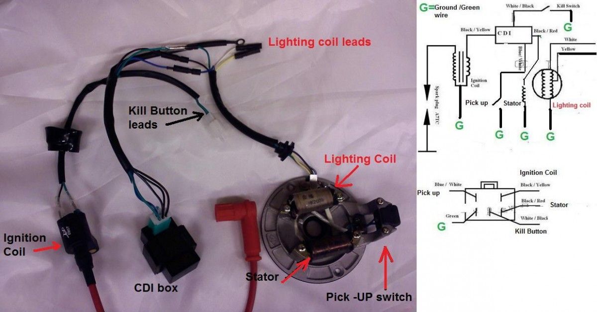
The capacitor discharge ignition (CDI) as you know is that black box on your motorcycle that basically functions as the brain of the ignition and motor unit.
This unit is typically found underneath the seat.
It is so common in motorcycles now a days, and has all but replaced the old mechanical trigger mechanisms of the past (before 1980’s).
Before we get into the various steps on how to test your cdi box using a multimeter.
Let's understand a few critical components of the CDI to ensure that your testing is not just theoretical but is backed up by a firm and solid understanding of the underlying electronics involved.
Internal Workings of your CDI
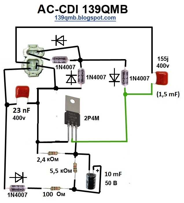
The CDI has the components as shown in the image below
Source: usman032.com
The alternator (exciter) coil is typically powered with an AC voltage ranging anywhere up to 400 Vac.
This passes through a forward biased diode and produces a DC voltage which is inturn fed to the micro-capacitor and the silicon controlled rectifier (SCR).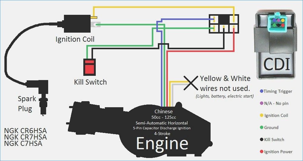
The SCR is further controlled by a pulse coil which dictates it’s open and close position.
Read More:>> Find the Best Multimeter under $50
When the SCR is closed. This creates a short circuit causing current to flow from the charged capacitor in the direction as shown below.
This charges the ignition coil before releasing the energy to the spark plug, and hence providing energy to the engine.
Symptoms of a defective CDIThere are various symptoms that can be derived from a defective cdi. Of which you will be able to use a multimeter to test. They are listed here below.
Misfiring engine
There are many reasons as to why an engine could misfire.
Getting the help of a professional mechanic would usually be your best bet. However a worn out ignition coil found within the cdi is a very common issue with misfiring engines.
Dead Cylinder
This occurs when one or more of the cylinders fails to fire properly.
Often what will happen is that the CDI could have a defective blocking/forward diode, creating fuzzy voltage signals which inturn confuse the spark plug’s firing mechanism.
Backfiring
This tends to happen at higher RPMS above 3000. It can be an issue on the stator, but it has been shown that a bad cdi can contribute to backfiring.
SafetyPlease ensure that whenever you are working with cdi parts or motorcycle mechanics you ensure that you use the typical Personal protective equipment.
The minimum that should be use cut resistant and water proof mechanical gloves, protective and protective eyewear.
I can tell you from experience working with electrical equipment that safety and the dangers that come from not protecting yourself adequately can be very dangerous.
CDI’s are active components that have capacitance inside although this is usually minimal (i.e. micro farads). You should not take your safety lightly.
Step 1 -Remove CDI box from motorbike
The CDI is usually connected with insulated leads and pin connectors. Disconnecting this from the motorcycle should not be too difficult.
Make sure that you do not work on the cdi immediately. Let it sit for at least 30 minutes to 1 hour to allow the internal capacitance to discharge.
Also during this step, it is important to run a visual inspection of your CDI. Typically damaged CDI’s have some form of mechanical deformation in the form of heat or damaged insulation from the casing.
Read More:>> Testing Purge Valve using a Multimeter
Step 2 – Testing CDI (Cold Test)
Here is the image we used above again as a reminder of the internal circuitry
This method requires us to test the cdi for continuity.
So what you would do is set your multimeter to continuity mode. First take the leads of the multimeter and connect them together.
If you are using a digital multimeter then you should hear a beeping sound.
Measure for continuity between all the ground and the various other points.
If your cdi is working well, you should not hear any sounds. If you do however hear any beeping sound as you are testing, then you cdi is faulty.
All is not lost at this stage, the cdi can still be rectified if you are able to fix the defective component.
Usually on a cdi when you have continuity between ground and any of the other terminal points , it either means that the diode, scr or the capacitor has failed.
Step 3 – Testing CDI (Hot Test)
There is an alternative method to testing the cdi box whilst it is still connected to the stator of the motorbike. Generally cdi boxes have a blue and white wire than comes from the stator to the cdi box itself.
When testing for continuity on the multimeter, it is important to test via the stator end rather than the cdi end.
This is because it is notoriously difficult to get any test lead connection through to a connected cdi box.
The voltage, continuity and resistance is generally the same as on the stator end.
There are a couple of things that you would want to test. Namely:
This will provide you a genera hot health status check of your cdi box. If the resistance values on your multimeter reading go outside of this range. It is worth checking it with a mechanic.
Read More:>>> Learn more about clamp meters vs multimeters
Final thoughts on how to test CDI box with a multimeterHaving a motorbike that does not fire correctly or produces cracky idling can be a pain to diagnose.
One thing that is often overlooked in checking the cdi for it’s health and functionality with a multimeter.
I hope this guide has provided you with additional insights as to how to test your cdi box with a multimeter.
ATTENTION!!! DO NOT SWITCH ON THE IGNITION WITHOUT THE HIGH WIRE, THE PLUG, OR IF THE PLUG IS NOT TWISTED INTO ITS PLACE OR IS NOT RELIABLELY EARTHED TO THE ENGINE BODY!!!
THE COIL WILL COME WITH A PROBABILITY OF MORE THAN 50 PERCENT!!! THIS IS ESPECIALLY RELATED TO "DRY" COILS OF THE TYPE FROM "VOLGA", "OKI" OR "MATIZ".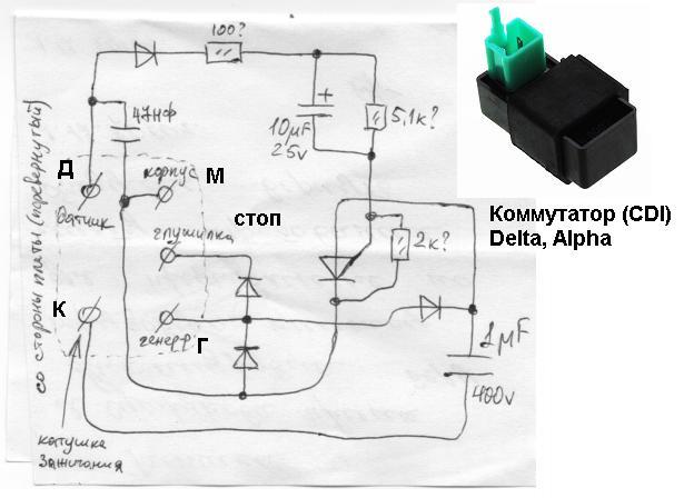
IN THIS COIL, THERE IS A BREAKDOWN INSIDE THE COIL AND THE INTERTURN SHORT CAN APPEAR!!! THE PRESENCE OF INTERTURN SHORT ON SIMPLE SYSTEMS WITHOUT PROTECTION AGAINST SHORT CLOCK DOES NOT INTERFERE TO WORK AND THE SPARK IS PRESENT, BUT NOT FOR LONG - AT THE END OF THE END THE COIL DIES AT ALL. MY SYSTEM HAS BUILT-IN SHORT PROTECTION AND WILL NOT WORK WITH PUNCHED COILS!!!
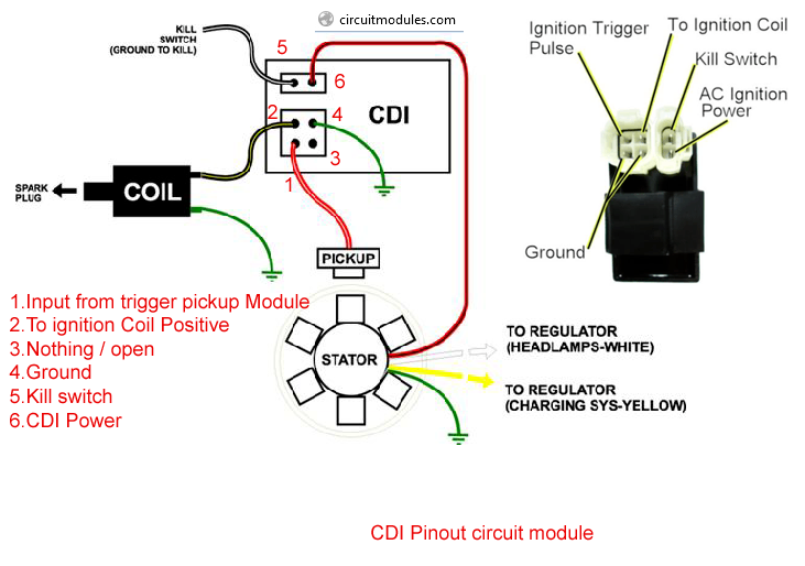
To connect the ignition control unit (BUZ) to the ATV's on-board network (only connector 1 is used), disconnect the standard CDI unit from its connector (or disconnect the DPK connector) and disconnect the BB wire of the standard ignition coil from the spark plug to the "signal" wire ( most often it is a blue or white-blue wire) DPK connect the BUZ input (blue wire), make sure that the second DPK wire (most often green) is connected to ground (sometimes it is connected to ground only in the CDI unit, sometimes directly in the generator)
Black wire BUZ to ground, the second black wire to the "-" DPK, yellow wire BUZ to + battery (battery) after the ignition switch (it is convenient to connect it to the "+" terminal of the cigarette lighter), white wire to the terminal of the ignition coil, Terminal " + "ignition coils through a 15 amp fuse !!! on + battery, BB wire to the coil and spark plug.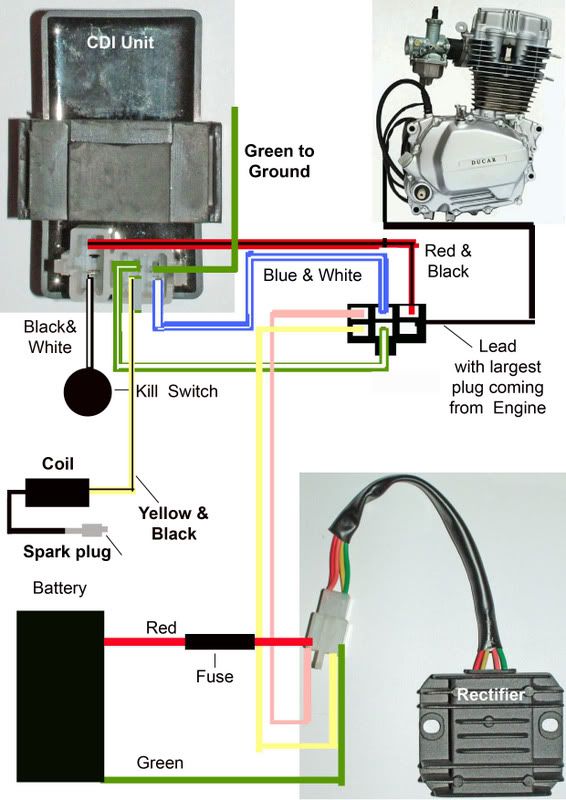 Increase the gap on the electrodes of the candle to 1 mm (If you are not sure that you can correctly increase the gap so that the contact surfaces of the candle remain strictly parallel, then you will have to learn how to do it :). Securely fix the ignition coil and BUZ on the quadra frame (the unit is fastened with self-tapping screws or M4 screws through the holes that are accessible when the cover is removed).
We strongly recommend that the block body be securely connected (electrically) to the quadra frame, if the body is attached to plastic - with an additional thick wire (to the wire terminal, terminal for the block mounting screw) connect it to the "-" battery or frame!
If this is not done, then in most cases nothing terrible will happen and everything will work fine anyway :o)
Everything, you can start it. As wound up, you should reduce the speed of the twentieth - most likely they will increase to 2000 - 2500 rpm.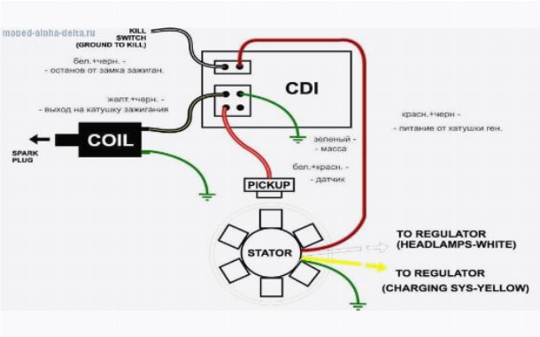
To return to the standard ignition system: disconnect the connector 1 BUZ, the standard CDI unit back into its place, the BB wire from the standard coil to the spark plug.
Connector number 2 is up to you :o)
There are a few points to pay attention to when installing and starting the system. Here is a list of what caused the ignition to work poorly on different quadrics:
 (Better just buy a new NGK spark plug)
  (once they forgot to connect the second wire from the induction sensor to ground - naturally, nothing worked and the blue LED did not light up ... not in all quadrics it is shorted to ground directly in the generator ...)
 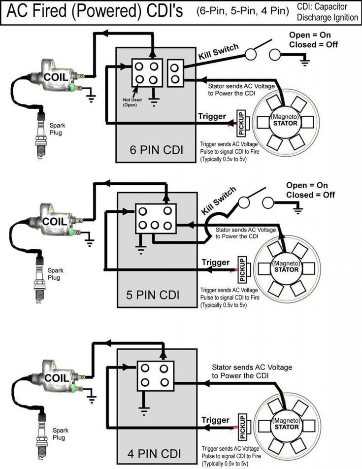 If it's too big, it won't start well. (in the new version, the problem of a small gap is solved - everything works without increasing it)
IN THIS COIL, THERE IS A BREAKDOWN INSIDE THE COIL AND THE INTERTURN SHORT CAN APPEAR!!! THE PRESENCE OF THE INTERTURN CLOSURE OFTEN DOES NOT INTERFERE TO WORK AND THE SPARK IS PRESENT, BUT NOT FOR LONG - AT THE END OF THE END THE COIL DIES AT ALL.
To connect the ignition control unit (BUZ) to the ATV's on-board network (only connector 1 is used), disconnect the standard CDI unit from its connector (on some models, the standard unit cannot be disconnected, see clarifications in the descriptions) or disconnect the DPK connector, disconnect the BB wire a standard ignition coil from a candle, to the "signal" wire (most often it is a blue or white-blue wire) of the KDP, connect the input of the BUZ (blue wire) , )
Black wire BUZ to minus the battery (battery), make sure that the second wire of the DPK (let's call it "-" DPK) (most often green) is connected to ground (sometimes it is connected to ground only in the CDI unit, sometimes directly to the generator itself, if not, we connect it to the “-” battery, the yellow wire of the BUZ to + the battery after the ignition switch (most often it is the black wire), the white wire to the “-” terminal of the ignition coil, the “+” terminal of the ignition coil through a 15 amp fuse to + battery, BB wire to coil and spark plug
Everything, you can start. As wound up, you should adjust the speed of the twentieth.
To return to the standard ignition system: disconnect connector 1 BUZ, the standard CDI unit into its place in its socket, the BB wire from the standard coil to the spark plug.
Connector number 2 is optional, add. functions are activated by shorting the desired wire to MASS !!! If they are not needed, insert a chip into the connector anyway so that WATER does not get in !!! it is necessary !!!
There are a few things to pay attention to when installing and starting up the system. Here is a list of what caused the ignition to work poorly on different quadrics: