by Sam Orlovsky
Categories Learning
Tags Multimeter
A motorbike, ATV, or side-by-electrical side system comprises three parts: the battery, the stator, and the regulator/rectifier. If your device’s electrical system isn’t charging, one of those three components is most likely to blame. The only way to know which component is faulty is to test them all.
But how do you test a regulator/rectifier? A digital multimeter with a diode test mode is required to test a regulator/rectifier. If you don’t already have one, this is a fantastic time to obtain one.
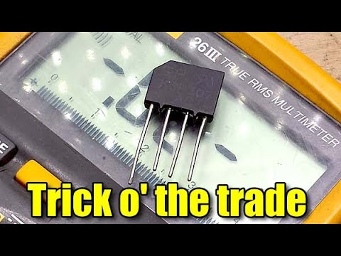
In general, to test a rectifier with a digital multimeter, you must follow these steps. First, set the multimeter to measure resistance (Ω). Connect the cathode to the negative black lead and the positive red lead to the anode. The diode test is forward-biased in this setup, and you should receive a resistance value between 1 KΩ and 10 MΩ. Then, change the leads to the opposite ports.
As we proceed, we will dig deeper into how to test a rectifier with a multimeter.
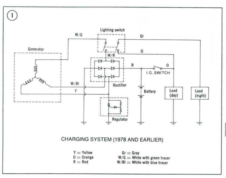
What Exactly is a Rectifier?A regulator/rectifier is electronic equipment that transforms the AC electrical current generated by the generator into DC electrical current and transmits it to the battery. The rectifier section of the regulator/rectifier unit is in charge of converting the current from alternating current to direct current. At the same time, the regulator portion is in charge of managing the amount of current supplied to the battery so that it does not harm it. (1)
A regulator/rectifier is made up of a series of diodes. A diode permits an electrical current to pass through it in one direction while preventing it from not moving to the opposite flow. The passage of electrical current via a diode is known as bias. Forward bias refers to the allowed direction of current flow, and reverse bias refers to the blocked direction of current flow. (2)
Confirm that a regulator/rectifier is operating correctly. You must test each of its diodes to ensure that they are appropriately forward biasing and reverse biasing. Regulator/rectifier units differ from one another and from one manufacturer to the next. Other regulators/rectifiers are more difficult to test than others, and some cannot be tested.
Video | Rocky Mountain ATV MCA regulator/rectifier has two electrical connections. These are typically a gray three-terminal connection for receiving current from the stator and a black two-terminal connector for sending current out to the battery. The positive is the inner terminal on the black two-terminal connection, while the negative is the outer terminal. Some regulator/rectifiers feature a black three-terminal connection with a ground terminal in the middle.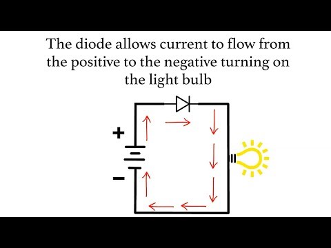
Note: Set your multimeter diode test mode when examining a regulator/rectifier.
Test 1: Forward Bias (Positive Circuit Diodes)Video | dhiko mech It means that the diode prevents electrical current from flowing back through (reverse bias) and operating correctly.
| Single Phase Rectifier | 3 Phase Rectifier |
| Single-phase rectifiers have a single-phase AC power input. The structures are fundamental, using only one, two, or four diodes. | 3 phase rectifiers take three-phase AV power as an input. Structures require three or six diodes, one for each stage of the transformer secondary coil. |
| A single-phase rectifier converts using only a single phase of a transformer’s secondary coil, and diodes are linked to the secondary winding of a single-phase transformer. It results in a significant ripple factor. | Three-phase rectifiers are utilized to lower the ripple factor instead of single-phase rectifiers. When employing extensive systems, three-phase rectifiers are favored over two-phase rectifiers.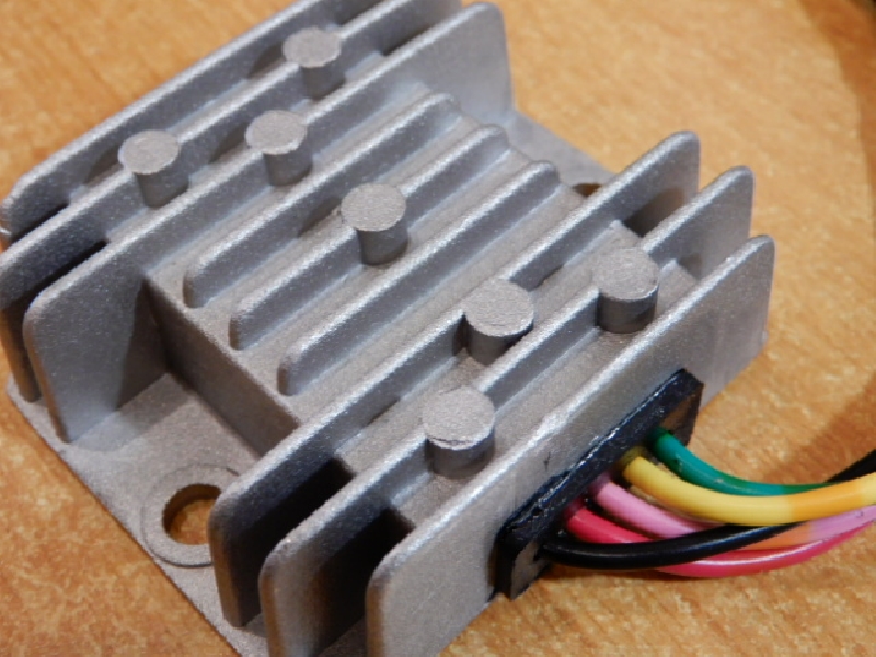 |
Take a look at some of our related articles below.
References
(1) generator – https://www.britannica.com/technology/electric-generator
(2) electrical current – https://www.britannica.com/science/electric-current
Video References
Rocky Mountain ATV MC
Dangar Marine
dhiko mech
How helpful was this article?
Were Sorry This Was Not Helpful!
Let us improve this post!
Please Tell Us How We Can Improve This Article.
About Sam Orlovsky
Certifications: B.E.E.
Education: University Of Denver - Electric Engineering
Lives In: Denver Colorado
Electrical engineering is my passion, and I’ve been in the industry for over 20 years. This gives me a unique ability to give you expert home improvement and DIY recommendations. I’m not only an electrician, but I also like machinery and anything to do with carpentry. One of my career paths started as a general handyman, so I also have a lot of experience with home improvement I love to share.
| Reach MeCategories Learning Tags MultimeterPawandeep Singh
Published Jun 21, 2022
+ Follow
Do you think your regulator rectifier isn’t working properly? It is a crucial component of your bike, so if anything is wrong, you should know how to detect symptoms and get it fixed accordingly.
How does the regulator rectifier work?
Modern bikes have batteries featuring electrical charging circuitry. A regulator rectifier is a standard component of this circuitry – as is evident from the name; this part regulates and rectifies voltage. The bike’s alternator start coil generates AC voltage. Usually, motorcycles feature a three-component system that contains three wires, linking the stator to the regulator rectifier. Some bikes have single-phase designs, where there are two wires instead of three. The regulator rectifier converts AC power into DC power, and then regulates the DC power to ensure the power doesn’t go over around 14.5 volts. At this point, the DC voltage is routed to the battery.
What are the symptoms to watch out for?
In general, there are two ways that the regulator rectifier can fail – take a look:
The diode could burnout and lead to battery drainage
If this happens, you won’t’ have problems recognizing signs such as poor starts, fluctuating meter readings, and dimmed headlights. In case you notice these signs, it is advisable to check the voltage using a voltmeter. If the reading goes below 13 volts, the bike will begin to drain the battery. It is only a matter of time before the engine stops completely,
The shunt regulator burns out
If the regulator rectifier can’t moderate the voltage levels, the battery will overcharge. Use a voltmeter to diagnose overcharge. If the readings are over 17 volts, it means the regulator rectifier is failing to convert the excess power. All the extra voltage could make headlights extremely bright before blowing out.
How to test the regulator rectifier?
In most motorcycles, the regulator and rectifier are located together in the same unit, but other older models have them installed separately. Take a look at what you have to do for checking failure:
· Disconnect the wires in the bike and switch the multimeter to diode function.
· Take a look at the positive diode by inserting the positive lead into the bike’s positive diode.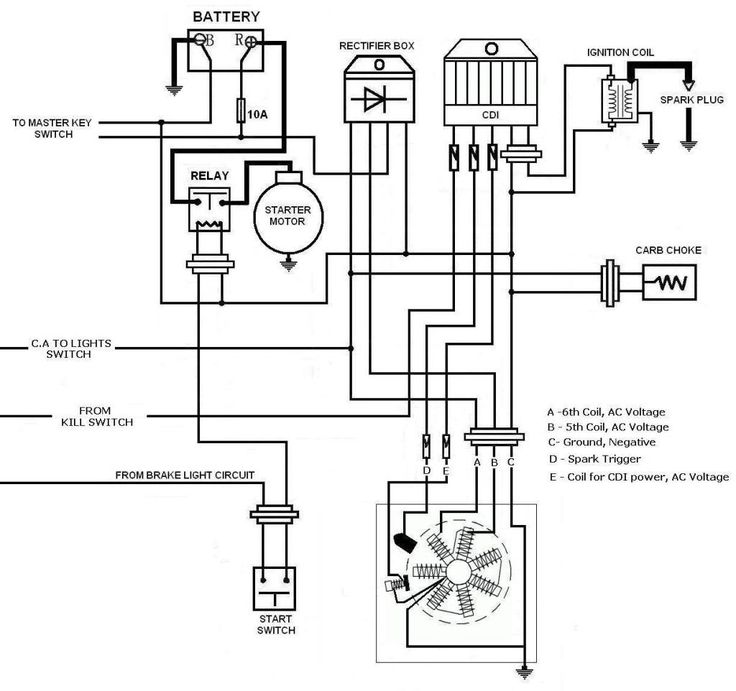
· Next, connect your negative lead to the stator inputs. You shouldn’t see any readings on the meter yet.
· If everything looks good at this point, connect the positive diode to the negative lead before connecting the positive lead to all stator inputs. At this point, the meter should show you something, but the specific numbers are irrelevant.
· Repeat for the negative diode by connecting the positive lead to the negative diode and connecting the stator inputs and negative lead.
· The meter shouldn’t show any reads when you connect the positive lead and stator inputs.
· To check the regulator, connect the meter leads to the bike’s battery as it is running. The reading should not be higher than 14.5 volts or lower than 13.5 volts. If the reading is higher, this means the battery is overcharged and you may need to replace the regulator rectifier.
What is the solution?
If your regulator rectifier is failing, then you have to get it replaced immediately.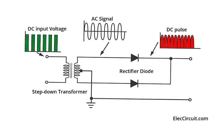 It is imperative to detect signs early on, so you can replace the component for a relatively affordable price and potentially avoid complete battery failure down the road.
You should always examine the condition of components in the bike’s electrical circuitry, because issues with any part could cause failure. If your regulator rectifier has already died, take a look at the internal connections. A manufacturing defect can lead to failure as well.
ATV electrical system failure is a serious problem. And if this situation occurs, you should first check the ATV regulator relay. It is this node that most often fails both on expensive equipment and on Chinese devices from the catalog https://dvako.com.ua/kvadrocikly/. So how do you diagnose a relay?
The Regulator Relay is an important component of the quad's electrical system and is responsible for maintaining the voltage within the operating range. The fact is that the generator is responsible for converting power into energy. But the voltage of the current it generates directly depends on the rotation of the shaft, energy consumption and even environmental conditions. And to smooth out the differences, a relay-regulator is used.
System element performs several tasks at once:
That's why it's important for a rider to know how to test an ATV's regulator relay. This will help to avoid damage to the electrical system, rapid battery discharge, and even ignition of components.
If a component fails, it will cause a number of problems. For example, if the voltage in the system is low, the battery will simply stop charging. There will also be problems starting the ATV, and its headlights will begin to shine dimly.
High voltage will damage the battery of the quad. A white coating will begin to form on the battery, the amount of electrolyte will decrease or it will begin to boil.
That is, replacement or repair of the ATV voltage regulator relay is necessary if:
If any of these problems occur, you need to figure out how to test the regulator relay on the ATV.
The first step in identifying the problem is to check the battery voltage. You need to turn off the quad and use a multimeter to take readings from the battery.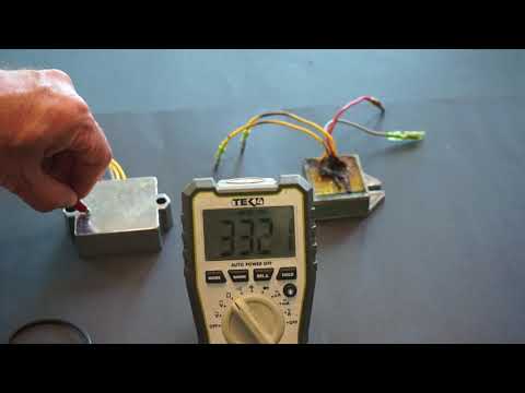 After that, you need to start the engine of the ATV. If the battery is charging, the voltage should rise. But if there are problems in the system, the numbers, on the contrary, will decrease.
So how do you test the ATV regulator relay? To do this, we need to dismantle the component or open access to it. After that, you should set the multimeter to the dialing mode up to 200 kOhm. Then you need:
In the first position, you should have readings in the range of 18-19 kOhm. But in the second position of the probes on the multimeter there should be no more than 33 kOhm.
Please note that there is a relay with 5 wires (red, green and three yellow). In this case, you should check if there is a short circuit between the plus and minus of the element.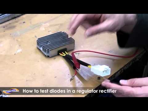 If there is no resistance, then it is necessary to replace or repair the ATV relay-regulator.
Then you should switch to dialing mode and connect one probe to minus. The second probe alternately checks all the wires coming from the winding. In this case, the diodes should not show any results. Then reverse the polarity of the probes and repeat the procedure (readings must be greater than zero). A similar call is performed with a plus.
The generator is one of the main mechanisms of any ATV. During the operation of the ATV, it creates an electric current from the rotation of the crankshaft. During the operation of equipment, it is constantly in operation, so after long-term use there is a possibility of its breakdown.
All ATVs presented on the page https://sh.sh3011.ru/kvadrocikly/cforce-600-eps.html are powered by internal combustion engines. With the help of a powerful motor, the necessary cross-country ability and speed are provided. While the engine is running, the generator continuously generates electricity, which is used to power various electrical appliances and the ATV.
ATV alternator breakdowns are not uncommon, due to the constant operation of this unit. If there are problems with its functioning, there is usually a serious disruption in power generation. If this happens, then you can independently check the main elements of the entire system. To carry out verification work, you can use a conventional multimeter. Everything must be done in the following sequence:
ATV alternator repair procedure involves replacing it because this unit is rarely repaired.
Repairing an ATV alternator is a complex process, so ATV owners most often just replace it with a new unit. The dismantling process includes the following steps:
This completes the dismantling work. Installation of a new unit is carried out using the same tools, only in reverse order.