Home » Misc » Metal valve stem installation instructions
Metal valve stem installation instructions
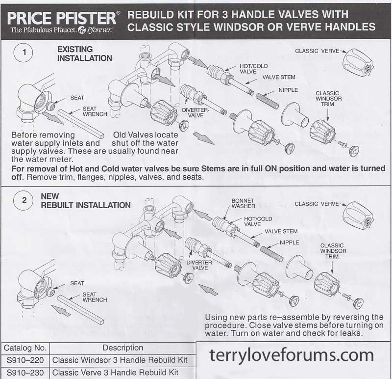
Tire-Man: Kit #3-6D Installation Instructions
~~~Serving Ridgecrest and the entire Indian Wells Valley for 43 years ~~~
Kit #3-6D Installation Instructions
Kit #3-6D Installation Instructions
17" Dodge Dually and Chevy
(It is not necessary to dismount tires to install this kit.)
Dual valve stems on rear go the same direction (right or left) when installing, the outer wheel is turned backwards (so it will go in the opposite direction).
Deflate tires and remove the old stems.
Install front stems as you would any other metal valve stem, do not use thread locker on the nut. Inflate to proper air pressure.
Take curved outer valve stem, remove nut, concaved washer, & flat rubber gasket. Put a drop of thread locker on the threaded stem & insert stem through wheel & install flat rubber gasket, concave washer & nut. Position the stem 1 off center to the right & torque nut to 45" to 55" pounds. Inflate to proper air pressure.
Take long inside valve stem, remove nut, concaved washer, & flat rubber gasket. Put a drop of thread locker on the threaded stem & insert stem through wheel & install flat rubber gasket, concave washer & nut. Position the stem off center to the right & tighten nut to 45" to 55" pounds. Inflate to proper air pressure.
Rebalance all 6 tires. Caution -- when placing the outer rear-dual wheel on and off the balancer make sure valve stem is at 6 o'clock position (at the bottom).
Place both wheels on top of each other on the ground, check to see that the inner wheels valve stem is on the opposite side of the outer valve stem in the same hole. A picture is on backside of this instruction sheet.
If everything is lined up correctly now is the time to install the chrome plastic wheel liner.
Reinstall all wheels on vehicle & torque lug nuts to specifications.
Note
This dually kit works with 95% of all simulators on the market today. The other 5% will have to be modified slightly. (If a modification is needed, make a small notch to allow the simulator to clear the outer wheels valve stem.) Do
NOT try to modify the outer valve stem.
Enlarge
17" Dodge Dually
The picture to the left shows the final position of the valve stems when they are mounted on the vehicle. Notice both valve stems come through the same hole. Use the blue thread locker that comes with the kit only on the stems with the nut on the inside of the tire. Available since 2/10/05
Any questions contact Chuck @ Tire Man Toll free: 1-888-889-8996
Kits Available:
Kit #1-6DCF: Fits older model Dodge, Chevy, & Fords Kit #2-6F: Fits late model E-350, E-450, & Ford trucks Kit #3-6D: Fits late model 17" Dodge duallys
I wish I could remember the name of our neighbor at FOY who suggested it is best to install metal valve stems on trailer wheels. If you’re still reading this blog, thank you! He also has an Arctic Fox trailer. He showed me photos of what he did to prevent damage of the stock valve stems on his trailer wheels. And, upon closer inspection, I discovered our rubber valve stems were also getting pretty beaten up. This was likely due to the TPMS valve caps we installed. And we finally replaced the rubber valves with metal stems for our trailer wheels.
Stock valve stem with aftermarket TPMS cap.
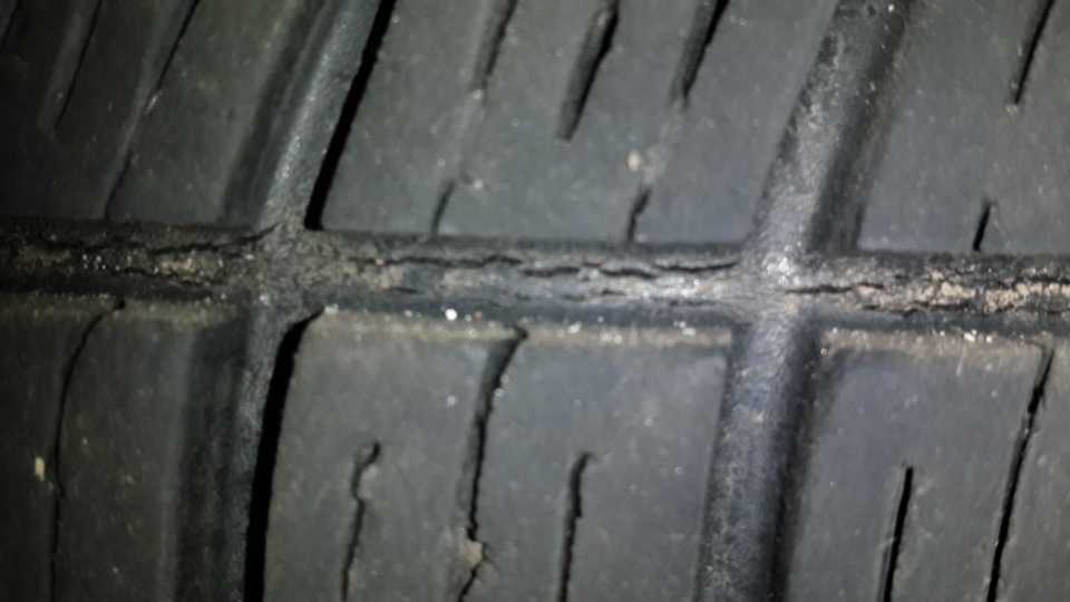
A Tire Pressure Monitoring System is a must-have for all full-time RVers. Simply compare the damage done due to a flat tire with and without a TPMS. However, the stock rubber valve stems on most trailer wheels cannot handle the additional weight of the sensor caps. See what happens in these first photos. Centrifugal force causes instability of the stem while in motion at high speeds. This can damage the TPMS caps, mar the rims, and weaken the valve stems.
TPMS sensor cap damage due to rubber valve stems.
Our rubber valve stems were clearly allowing the caps to flop around at high speeds.
Abrasion from the TPMS caps hitting the wheels could have permanently damaged both the sensors and the rims. We do have small permanent grooves on a couple wheels. But fortunately, we installed metal valve stems on trailer wheels before the damage got any worse.
Rubber valve stems will weaken, crack, and develop slow leaks from the persistent wobble caused at high speeds. Metal valve stems on trailer wheels prevent this motion from occurring. When attached to metal valve stems, the TPMS sensor cap will remain stationary, at any speed.
Sturdy metal valve stems prevent TPMS damage.
We installed metal valve stems on our truck tires first. We finally go around to installing them on our trailer. I am much more confident now that our valve stems and TPMS caps are no longer prone to damage. And, we are safer now from the potential for a blowout caused by a broken valve stem.
So, where to get metal valve stems for trailer wheels?
Not all tire shops stock tires, valve stems, and supplies for RVs and trailers. You may need to find a heavy duty truck shop that services tractor-trailer rigs. Better yet, purchase your own valve stems. I found metal valve stems on Amazon that fit our trailer and truck. You can then take them to be installed at any tire shop. That’s what we did.
Protect you TPMS with metal valve stems.
Or, you could do a DIY job and replace the valve stems yourself. Personally, I don’t recommend following instructions that simply say, “Pull the old valve stem out and put the new valve stem in.” I also recommend having the tires balanced with the TPMS caps on to ensure proper weigthing. With the added wight of the TPMS and metal valve stem, that just makes sense.
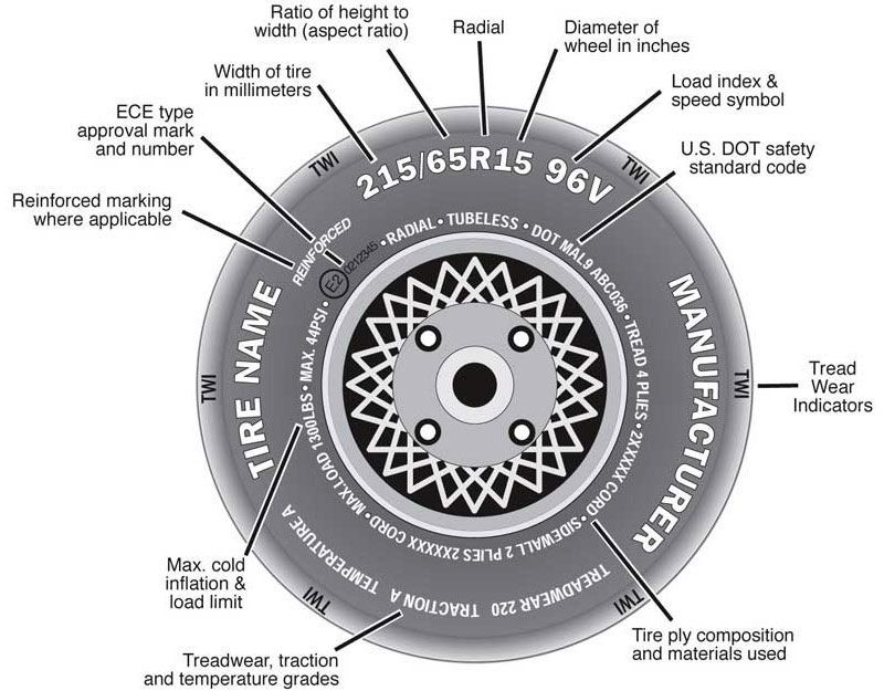
What size valve stem for trailer wheels?
But how do you know what size metal valve stems to get for your truck or trailer? Do your homework. I found a couple discussions that confirmed .453″ metal valve stems were the right size for our truck and trailer wheels.
Cummins Forum: Valve Stem Replacement
Turbo Diesel Register: Tire Valve Stem Diameter?
I purchased these CKAuto Metal Valve Stems because they fit both . 453″ & .625″ rim holes, common to most light duty trucks and trailer wheels.
CKAuto metal valve stems fit two rim hole sizes.
Do you have a TPMS for your RV or truck and trailer? If not I highly recommend you get a Tire Pressure Monitoring System. Get the Tire-SafeGuard system now, or read why here. If so, have you installed metal valve stems on trailer wheels yet? To protect your TPMS and wheels, don’t delay. Confirm your size and get metal valve stems here to prevent further damage.
Miller TM830T Trough-O-Matic Automatic Metal Float Valve Instruction Manual
Miller TM830T Trough-O-Matic Automatic Metal Float Valve Instruction Manual
installation on the edge of gutters and tanks is quick and easy.
Accepts standard 3/4″ garden hose thread. Quick pipe mount with 3/4″ adapter (not included). nine0012
One piece float Manufactured from durable, maintenance-free polyethylene.
Adjustable neoprene valve seat for long life (models TM830 and TM830T).
Longer float uses up to 55 psi water pressure for 245 gph.
Each automatic float valve contains:
1 metal valve body
1 plastic insert with hole (already assembled)
1 Hose Washer (Already Complete)
1 Float Assembly
1 Large Cotter Pin 1/8″ x 2-1/4″
2 C-Brackets
2 Thumb Screws 1/4″ -20 x 2″
2 mounting screws 1/4″-20 x 3/8″ (TM830)
4 mounting screws 1/4″-20 x 3/8″ (TM830T and TM830AS)
2 L- brackets (TM830T and TM830AS)
4 screws #10 x 3/4″ (TM830T and TM830AS)
1 anti-siphon stem (TM830AS)
1 Antisiphon valve case (TM830AS)
1 Little Shplint 1/8 ″ x 1-1/8 ″ (TM830AS)
The necessary tools:
Sprinkle with a straight blade
Sprinkle with a cross-shaped moit of
Square with semi-round jaws
Food grade anti-seize compound
Assembly instructions (TM830, TM830T and TM830AS models):
Familiarize yourself with all components of the automatic float valve. nine0070 a. Open the loose parts bag and describe its contents. b. The plastic insert and hose washer are already installed in the valve body. Make sure the diaphragm insert and washer fit snugly into the valve body. in. The rubber valve seat is already attached to the float. Make sure the seat and pin fit snugly on the float.
Position the float assembly inside the valve body and thread a large 2-1/4″ cotter pin through the body and float assembly (See Figure 1). Slightly spread the ends of the large cotter pin with pliers. When properly installed, the rubber float assembly should rotate freely on a cotter pin inside the valve body. nine0012
See installation instructions.
TM830AC
Familiarize yourself with all components of the automatic float valve. a. Open the loose parts bag and describe its contents. b. The plastic insert and hose washer are already installed in the anti-siphon valve body. Make sure the diaphragm and washer are tight against the anti-siphon valve body.
Place the anti-siphon valve stem assembly in the float slot and insert a 1-1/8” cotter pin (smaller of the two cotter pins) through the float and valve stem assembly (see figure 2), then spread the end of the cotter pin slightly open. When properly installed, the valve stem assembly should rotate freely on the cotter pin inside the float. nine0012
Screw the anti-siphon valve body completely into the valve body.
Place the float assembly in the valve body and thread a large 2-1/4 in. cotter pin through the body and float assembly (See Figure 3). Slightly spread the ends of the large cotter pin with pliers. When properly installed, the float assembly should rotate freely on a cotter pin inside the valve body.
See installation instructions.
Installation Instructions:
Fitting a standard tank to the rim (all models):
Insert both C-brackets into the valve body as shown (see figure 4). Note: Use the top mounting holes in the valve body to keep the water level about 4 inches below the rim. Use the bottom mounting holes in the valve body to keep the water level about 2-3/8 inches below the rim.
Attach each C-bracket to the valve body with 3/8 in. machine screws. nine0012
Apply food grade anti-seize to the threads and connect the water line.
Position the automatic float valve assembly over the rim of the tank.
Insert the knurled screws through the C-brackets and tighten.
Test the operation of the automatic float valve.
Wide End Tank Mount (TM830T and TM830AS Models):
Insert both L-brackets into the valve body as shown (see Figure 5). nine0012
Attach each L-bracket to the valve body with 3/8 in. machine screws.
Attach a C-bracket to each L-bracket with 3/8” machine screws. Note: There are two positions on the L-bracket that allow you to adjust the width of the rim.
Apply food grade anti-seize to the threads and connect the water line.
Position the automatic float valve assembly over the rim of the tank. nine0012
Insert the knurled screws through the C-brackets and tighten.
Test the operation of the automatic float valve.
Extra Wide Rim Tank Installation (TM830T and TM830AS Models):
Insert both L-brackets into the valve body as shown (see Figure 6). 2. Attach each L-bracket to the valve body with 3/8 in. machine screws.
Apply food grade anti-seize to the threads and connect the water line. nine0012
Position the automatic float valve assembly over the rim of the tank.
Attach each L-bracket to the edge of the tank with two (2) self-tapping screws. Note: If necessary, pre-drill the tank rim at the desired location for the automatic float valve with a 1/8 in. bit.
Test the operation of the automatic float valve.
1450 West 13th Street Glencoe, MN 55336 Customer Service 800-260-0888 FAX 651-982-5101 For more information, visit www. miller-mfg.com
Parts
Miller Manufacturing, Glencoe, MN 55336 USA www.miller-mfg.com 9017
9017 Documents 9017 Resources
Miller TM830T Trough-O-Matic Automatic Metal Float Valve [pdf] Instruction Manual Metal float valve
Published by millerTags: Metal float valve, miller, TM830, TM830AC, TM830T, TM830T automatic metal float valve Trough-O-Matic0 Automatic float valve 404 - Page not found
Sorry!
The page you are looking for may have been deleted, renamed, or temporarily unavailable. You can go to the main page or use the site map:
About company
History of VEZA
Manual
Production
Research and development
nine0011 References
History of VEZA
Manual
Production
Research and development
References
nine0011 News
Blacklist
News
Blacklist
Invalid powers of attorney
nine0021
Products
Air conditioners
Fans
General industrial fans
Smoke ventilation
Industrial radial fans VIR
Marine fans
Special purpose ventilation units
Accessories for fans
nine0011 Refrigeration equipment
Thermal points, Control units
Automation
Valves, hatches and skylights
Fire dampers
nine0011 Valves for general industrial and special purposes
Valves and fittings Marine
Smoke hatches, aeration hatches, anti-aircraft lamps, easy to drop and roof access hatch

 If you’re still reading this blog, thank you! He also has an Arctic Fox trailer. He showed me photos of what he did to prevent damage of the stock valve stems on his trailer wheels. And, upon closer inspection, I discovered our rubber valve stems were also getting pretty beaten up. This was likely due to the TPMS valve caps we installed. And we finally replaced the rubber valves with metal stems for our trailer wheels.
 Abrasion from the TPMS caps hitting the wheels could have permanently damaged both the sensors and the rims. We do have small permanent grooves on a couple wheels. But fortunately, we installed metal valve stems on trailer wheels before the damage got any worse.
 You may need to find a heavy duty truck shop that services tractor-trailer rigs. Better yet, purchase your own valve stems. I found metal valve stems on Amazon that fit our trailer and truck. You can then take them to be installed at any tire shop. That’s what we did.
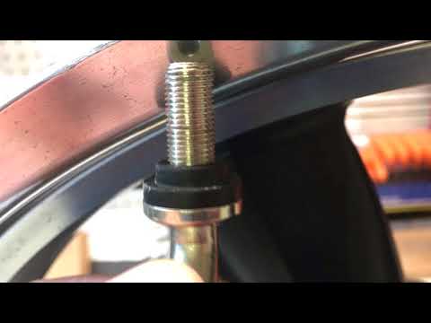 453″ & .625″ rim holes, common to most light duty trucks and trailer wheels.
 nine0070 a. Open the loose parts bag and describe its contents.
 Use the bottom mounting holes in the valve body to keep the water level about 2-3/8 inches below the rim.
 miller-mfg.com
 Inyokern Road