DREMEL
Country of Origin Italy. Country of Origin is subject to change.
Cutting wheels are thin discs that use their edge to cut, trim, and slot various materials. The wheel face should not be used for material removal as doing so can weaken the wheel and cause it to shatter. These cut-off wheels connect to a mandrel, which attaches to the rotary tool. The mandrel sets the wheel away from the tool tip to provide clearance for making cuts.
Tap image to zoom.
Roll over image to zoom.
DREMEL
Country of Origin Italy. Country of Origin is subject to change.
Cutting wheels are thin discs that use their edge to cut, trim, and slot various materials. The wheel face should not be used for material removal as doing so can weaken the wheel and cause it to shatter. These cut-off wheels connect to a mandrel, which attaches to the rotary tool. The mandrel sets the wheel away from the tool tip to provide clearance for making cuts.
Sort
Vehicle Info
Filters
Searching outside the recommended fitment range
Modification may be required to fit these wheels
×
The selected bolt pattern is different than the stock bolt pattern.
An adapter is required to make these wheels fit.
The stock bolt pattern is:
×
Sort by Quick Delivery×
Need Help Getting Started? Call Our Experts at 920-363-6060
Momo
RPM Evo Gray Polished
18x8 +40mm
Save up to $20. 00 when adding tires to package
Free Mount & Balance with Tire packaging!
$ 823.36
SET OF FOUR
Backordered
Starting at $75/mo Affirm
Momo
RPM Evo Gray Polished
17x7.5 +38mm
Save up to $20.00 when adding tires to package
Free Mount & Balance with Tire packaging!
$ 759.56
SET OF FOUR
Backordered
Starting at $69/mo Affirm
Momo
RPM Evo Gray Polished
17x7. 5 +35mm
Save up to $20.00 when adding tires to package
Free Mount & Balance with Tire packaging!
$ 744.00
SET OF FOUR
Backordered
Starting at $68/mo Affirm
Momo
RPM Evo Gray Polished
16x7 +35mm
Save up to $20.00 when adding tires to package
Free Mount & Balance with Tire packaging!
$ 677.20
SET OF FOUR
Backordered
Starting at $62/mo Affirm
Momo
RPM Evo Gray Polished
16x7 +38mm
Save up to $20. 00 when adding tires to package
Free Mount & Balance with Tire packaging!
$ 677.20
SET OF FOUR
Backordered
Starting at $62/mo Affirm
Momo
RPM Evo Gray Polished
16x7 +42mm
Save up to $20.00 when adding tires to package
Free Mount & Balance with Tire packaging!
$ 677.20
SET OF FOUR
Backordered
Starting at $62/mo Affirm
Momo
RPM Evo Gray Polished
15x6. 5 +38mm
Save up to $20.00 when adding tires to package
Free Mount & Balance with Tire packaging!
$ 594.84
SET OF FOUR
Backordered
Starting at $54/mo Affirm
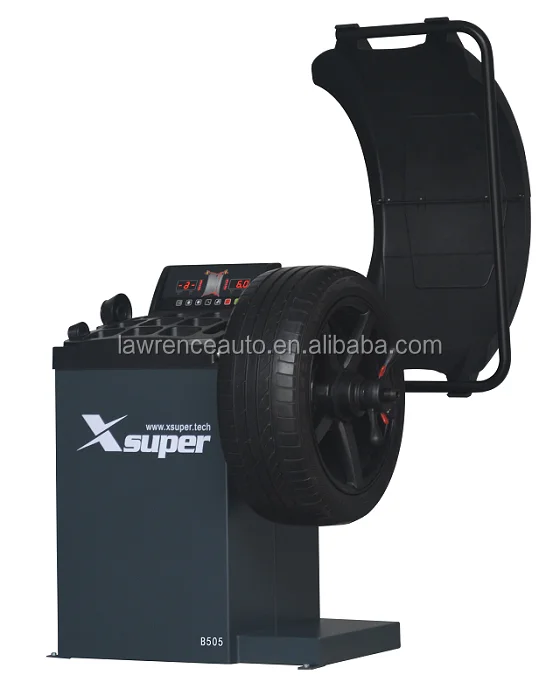
Main technical features:
Drive size up to 24 inches
Hexagonal mounting rod on automatic machines
Robust mounting head for heavy duty applications
Plastic pads for clamping jaws for working with alloy wheels nine0003
Clamping jaws made of solid steel
Mounting table made of durable steel
The top rack on the automatic machine is made of strong thick steel
Square mounting rod on semi-automatic machines
Flip top rack
Ergonomic stand tilt handle nine0003
Folding rear rack
Reinforced mounting post bolting
Chrome plated crowbar
Squeezing paddle with rubber dampers and pads
Machine controls
High strength pneumatic cylinders
Air filter unit nine0003
Retention device for lubrication
Unpack the machine according to the instructions. Remove the packaging and inspect the device for damage and accessories. If you have any doubts about the integrity of the equipment, contact the service/seller. Keep all materials away from children. Dispose of packaging materials properly without causing environmental pollution. Remove the top of the packaging, side racks and bottom pallet and store in a safe place. nine0003
Attention: parts are coated with special anti-corrosion oils that can attract dust, clean them if necessary.
Place for installation of the device must comply with safety requirements, consider the overall dimensions of the machine: 2000x900x760 mm. The device must be installed in close proximity to the power supply and the pneumatic line. Place the machine on a level concrete floor or other firm base. It is possible to fix the machine with 4 anchor bolts to avoid unnecessary noise and vibration. Leave enough space for machine operation and maintenance. At least 1m from the front sides and at least 0.5m behind, so that the various operations performed are not limited. (See figure 1). If the machine is located outdoors, a protective cover must be used. Never use the machine near flammable gas. nine0003
Figure 1 Tire Changer Layout
Move the column and column and put them on a soft pad
Attention: when you lift the column, the arm may fall out freely, be careful!
Install the return spring: use a 6 mm hex wrench for the internal screw that is in the plastic cover. Take a square post, put a spring on it, put the plastic cover back on and tighten the screw (As shown in picture 2). nine0003
Figure 2. Post
Use 6mm to mount the post. hexagon wrench to remove screws J and washers K, remove side cover L. Pull piston rod H up, align pin hole H with stand base. Lift up the post A (As shown in figure 3), align the pin holes in the post, base case, insert the pin B, tighten screw D and washer C (M12x25 screw).
Figure 3.
pin connection diagram nine0003
Figure 4. Stand Tilt
Pull the stand slowly forward when the hole between the stand and stem aligns, insert pin E, use washer F and spring clip G to fix. Install the stand straight and finish mounting. Install holder I: insert the two ends into the corresponding holes on the right side of the body (As shown in figure 3). Connect the hose in the rack: Connect hose M to regulator B. (As shown in Figure 5)
Figure 5 Hose connection
Attention: when the device leaves the factory, regulator B is already set to the desired pressure (4 bar), please do not adjust it yourself!
Install the side cover (As shown in figure 3) using 4 screws J and washer K to fix it. Loosen the 2 screws with a wrench (As shown in Figure 6). Use a hoist to lift the equipment, pull out the pallet, move the machine to the prepared installation site.
Figure 6. Lifting equipment using a hoist
Before installation, make sure that the power supply and compressed air supply meet the specifications indicated on the nameplate of the device. Any electrical connections must be made by a specially trained person. The outlet must be located within sight of the operator. Positioning height between 24-67 inches.
The device must be grounded .
Connect the inflation gun A to the air filter sleeve 1 (picture 7)
Figure 7. Connecting the inflation gun
Connect the compressor to the coupling on the air filter 2 (Figure 7)
Note: The tire changer is not equipped with overload protection. Connect the power supply in accordance with the manufacturer's wiring diagram. Otherwise, the manufacturer is not responsible for accidents.
Operation test: After turning on the power, press the pedal L (as shown in figure 8), the turntable will start to rotate clockwise. This test is very important. nine0003
Figure 8. Turntable Rotation
Air Regulator, Gauge, and Lubricator Assembly See Figure 9
Figure 9. Regulator, Air Filter, Gauge, and Lubricator Assembly
Adjust the pressure: there is a button for regulator 3. The pressure can be increased or decreased by turning clockwise/counterclockwise. After adjusting the working pressure, press the button down to lock it. Air filter 2 filters compressed air from water and various impurities. When water and various impurities have reached the red line, open the valve to drain them. Lubricator 1 is used to add a certain amount of lubricant to the air to lubricate the moving parts of the cylinder. Depress the pedal K 3-5 times, a drop of lubricant should fall into the cup on the regulator. If this does not happen, adjust the adjusting screw. nine0003
Attention: do not operate the equipment until you have completed training with qualified personnel. Wear appropriate personal protective equipment such as goggles, earmuffs and work boots when operating the machine. Check that the voltage, compressed air source and oil level are in accordance with the requirements of the application.
To avoid damage when fitting/removing wheels, especially those made of light alloy, use a special tire tool. To facilitate removal and improve tire protection, lubricate the area between the rim and tire bead where the tire changer contacts the edge of the rim with industrial grease or a soap solution. Pay special attention to the direction of rotation of the tire, marked with arrows on the tire. Install tires on a rim of the correct size. Check the tire and rim for damage (wear, cuts, punctures, excessive runout, erosion, etc.) before mounting the wheel. Never ignore the mounting/dismantling requirements for special wheels. When inflating a tire, make sure that the pressure increases evenly. Check tire surface and rim for air leakage as often as possible. nine0003
Attention: deflate the tire completely. Remove all foreign objects and weights from the edges of the disc (as shown in Figure 10). Lubricate the tire bead with a brush with grease or soapy water. Otherwise, the tire bead will stick to the rim.
Figure 10. Removing Foreign Objects
Place the tire between the rubber seal and the beader (Figure 11-a) 1 cm from its edge and the rim of the disc. Depress the pedal (Figure 11-b) to separate the tire from the rim. nine0003
Figure 11. Separating the tire from the wheel rim
This operation is repeated at various points on the tire until the tire bead is completely separated. Repeat the above steps on the other part of the tire to completely separate the tire from the rim.
Caution: When using the release lever, always make sure that no hand or other body part is between the bar and the release paddle.
Press the button on the shift knob B (as shown in figure 12), fix the stand, press pedal I, tilt the stand. Place the wheel on the turntable. The wheel rim should enter the grooves symmetrically and fit snugly on the clamping cams. nine0003
Figure 12 Tire Changer Symbols
Attention: different types of clamping jaws can be selected according to different types of rims. To clamp the bar, bring the clamping jaws together by pressing the machine pedal J (figure 13).
Figure 13. Bringing the clamping jaws together by pressing the pedal of the machine
If the clamping jaws do not match, move the jaws outward (2-3 cm from the edge of the rim) and place the wheel on the turntable. Position the rim close to the cams and depress pedal J to clamp the disc (figure 14). nine0003
Figure 14. Disc clamping on the tire changer
Press pedal I (as shown in figure 12) to lower the rack to the working position. Pull handle B (as shown in figure 15-a) and place the mounting arm together with the mounting head in a comfortable position as shown in figure 15-b.
Figure 15 Installing the mounting arm and mounting head
Press lever B to lock the mounting arm, making sure the mounting head is 1-2 mm apart. from the outer edge of the rim to avoid damaging the mounting head and mounting disc. nine0003
Insert the mounting lever near the mounting head (As shown in Figure 16), push it and the wheel from the opposite side (As shown in Figure 15-2), until the top edge of the tire is lowered until the other top edge of the tire is fixed on the tire changer. head (As shown in Figure 16).
Attention: to avoid damaging the inlet valve (nipple) mounting lever, keep a distance of 10 cm from it (as shown in figure 17).
Depress pedal L (As shown in Figure 15) to rotate the mounting bracket clockwise until all edges of the tire are clear of the rim. nine0003
Attention: for very hard low profile tires, the edges of which can easily come off, before turning the console clockwise, you can turn the console a little counterclockwise by 1-2 mm, fixing the mounting head inside the tire.
Fig. 16. Fixing the top edge of the tire on the mounting head
If the dismantling process is interrupted, stop the rotation of the console, press the pedal L (Fig. 15) so that the console rotates counterclockwise.
Figure 17. Safety distance from nipple
If there is a valve in the tire, remove it. Lift the wheel up to pry off the bottom edge of the wheel (see figure 18).
Figure 18 Prying off the bottom edge of the wheel
Depress pedal L to separate the bottom edge of the tire from the rim. Release lever I to raise the mounting head, remove the wheel and complete the disassembly.
Caution: Keep hands and other body parts away from moving parts. Never wear a necklace, bracelets or loose clothing while operating the machine as this can be dangerous! nine0003
Attention: check tire and rim size to make sure they match.
Clamp the rim firmly in the same way as when removing the wheel. Use lubricant, apply a thick solution of soap to the tire and rim. Mount the tire changer on the rim, release lever I to lower the changer back to its working position. Install the mounting head between the tire and the rim so that the tire bead rests against the head (see Figure 19).
| Figure 19. Installing the Bead Mounting HeadOnce the console has started moving, the edge of the tire should be under the head or rim of the rim as shown in Figure 20. Figure 20. Be sure to mount the tire bead correctly, avoid overlapping and pinching the tire bead. While doing this, press on the central part of the tire. Press the pedal L (figure 15) to rotate the console clockwise, as a result of which the lower bead of the tire will fall under the groove of the rim completely. nine0003 Figure 21. Correct position of the bead of the tire If a tube is to be mounted on the tire, place it carefully around the rim and avoid damaging it with the head. Keep it at the right distance throughout the installation process. To install the top bead of the tire, correctly position the bead of the tire on the head (Figure 21-A) so that the bead can slide into the groove (Figure 21-B). Apply pressure on the opposite side of the tire as you would when demounting, to evenly place the top edge of the tire into the groove of the rim (see Figure 22). nine0003 Figure 22. Uniform entry of the top edge of the tire into the groove of the rim Press pedal I (figure 12) to rotate the console, keep pressing the tire. Attention: it is not necessary to move the mounting arm and stand each time if the size of the mounted/dismounted discs is the same. During mounting, keep your head and hands away from the area between the mounting arm and the swing arm to avoid injury! nine0003 Tire inflation Attention: the pumping process can be very dangerous. Take all necessary precautions when performing this procedure. Make sure the air hose connection is secure before inflating the tire. The tire inflation process is shown in Figure 23. This machine is equipped with a pressure gauge to control the inflation pressure. Connect the inflation gun to the nipple on the wheel. Slowly depress the gun while inflating the tire to ensure that the pressure gauge reads correctly. Figure 23. tire inflation processCaution: Follow all safety procedures carefully. Otherwise, failure to comply may result in serious injury or even death. The manufacturer is not responsible for non-compliance with safety measures. Check wheel and tire sizes carefully to be sure they fit. Make sure the tire is not worn or damaged before inflating it. When a high inflation pressure is required, remove the tire from the tire changer and continue to inflate in the tire protector. Be careful when inflating a tire. Keep your hands and body away from the tire being inflated. The operator must take all necessary measures to ensure a safe environment when working with the tire changer. nine0003 Service Attention: only a trained technician can carry out maintenance. Figure 24. Cleaning with diesel fuel Otherwise, the normal operation of the machine cannot be guaranteed and may cause malfunctions of the device. Keep the working area of the machine clean, remove dust and other substances from moving mechanisms and parts. Keep the square pin and its moving parts on the rack clean and lubricated. (Cleaning can be done with diesel fuel as shown in figure 24). Keep the mounting head clean and lubricated so it can move freely. Lubricate moving parts and adjacent surfaces weekly with grease to reduce friction. Figure 25. Adding oil to the lubricatorFaults and causes, their elimination
Attention: other faults are of a purely technical nature and should only be checked and, if necessary, corrected by qualified personnel. |
Multistage non-self-priming horizontal high-pressure centrifugal block type pump with horizontal suction and vertical discharge.
This pump has a compact design and is equipped with a through motor pump shaft and a direction-independent mechanical seal. Sections, impellers and drive wheels are made of stainless steel, and the pump housing is made of cataphoretic coated cast iron. nine0003
It is suitable for water supply and pressure boosting, industrial circulation systems, process water, cooling water circuits. It can also be used in washing installations as well as irrigation systems.
Product features/benefits
Scope of supply
|
|
Weight, kg
 4028 [AISI420F]
 Pump body
Mechanical seal
Lower housing
Pump base
nine0392Pump base (in contact with the pumped liquid)
Bearings
Impeller
Sections
Static seal
Weight (gross), kg
Type of packaging
Height (gross), mm
nine0116Height (net), mm
Length (gross), mm
Length (net), mm
nine0116Item
Quantity per layer, pcs
Quantity per pallet, pcs
nine0116EAN number
Package properties
Type
Color
Width (gross), mm
Width (net), mm
Water Glycol (max.

 Correct location of the edge of the tire under the head
  As soon as 10-15 cm remains, stop the rotation to avoid tire damage. Check the tire for damage. Press pedal L again to rotate the console counterclockwise until the tire is in its original position.
  The inflation pressure must not exceed 3.5 bar. If the inflation pressure has exceeded the allowable limit, then press the button on the gun to relieve the pressure to the desired level. nine0003
 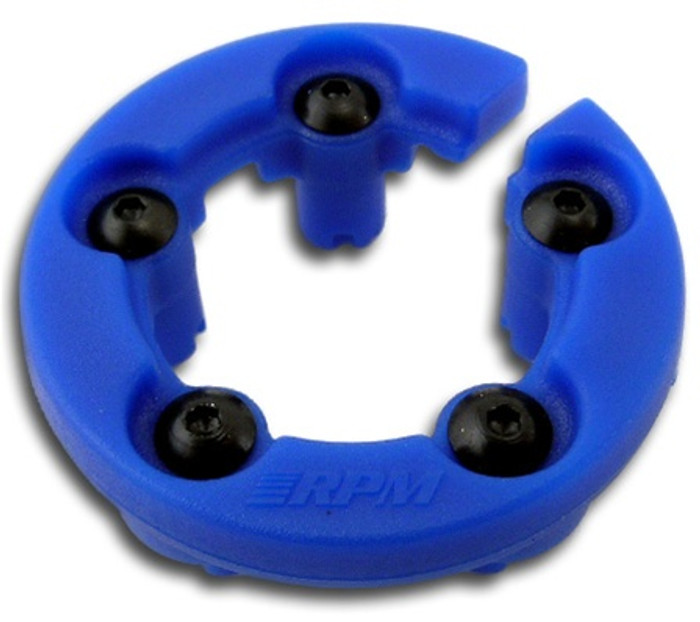 Before any maintenance, turn off the power by unplugging the mains plug from the socket. Turn off the compressed air supply, turn the air valve switch to the [OFF] position and press the [B] pedal 3 or 4 times to purge air from the residual compressed air system in the device. To keep the tire changer in good condition and prolong its service life, it is necessary to carry out regular maintenance in accordance with the operating instructions. nine0003
  Check the oil level in the lubricator regularly, if the level is below the second line, add SAE20 oil (Figure 25). Clean the air filter regularly from condensate and other substances. Check and adjust the drive belt tension regularly. Check all bolted connections regularly and retighten if necessary. Regularly check and adjust the locking of the rear hinged rack, when checking, keep a distance of 2 to 3 m from the rear of the rack.