Posted by Jefferson Bryant Know How
Flat tires tend to happen at the worst time in the worst places. If you are on the road or outside of normal business hours when your vehicle has a flat and the spare is missing or no good, you might feel stranded, but there is an option—a tire plug kit. This is something that anybody can do, you just need the right parts.
Liquid tire repair might get you down the road, but it could make your tire repair difficult and possibly damage the TPMS (Tire Pressure Monitor System) unit inside the rim itself depending on the formula. The best solution for an emergency tire repair is a tire plug. Made from cork and a gooey adhesive that keeps it place and seals the tire, a tire plug repair is an excellent way to get your car back on the road until you can get to a tire shop for a proper internal patch.
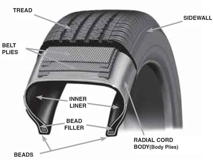
Installing a plug in your tire works for pierced tread area only. You cannot fix sidewall damage, compression breaks (from potholes, gravel roads or curbing) or any other type of catastrophic tire damage. The most common road hazards you will find are punctures from nails and screws. Fixing these issues are perfect for the good old fashioned tire plug. If you are wondering how long does it take to plug a tire, then the answer is just a few minutes. Most of the time is spent preparing to perform the plug itself. Here’s how to plug a tire with a plug kit.
You will need the following to make a tire plug repair:
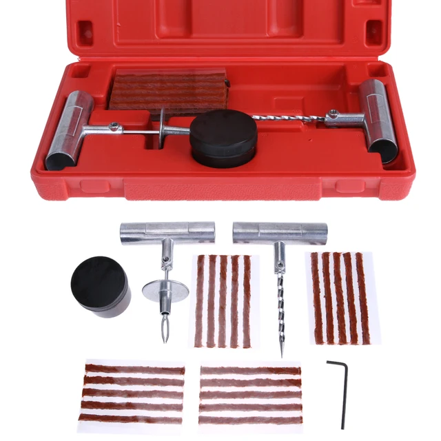
There are all kinds of tire plugging kits, but you want the most complete tire repair kit which comes with the plugs, the installation tool, and the reamer tool. Some flat tire repair kits just come with the plugs and installer, but the reamer tool is a necessary component to a good repair. Some tire plugging kits also come with liquid cement. You can use it or not, but the cement helps make a more permanent repair.
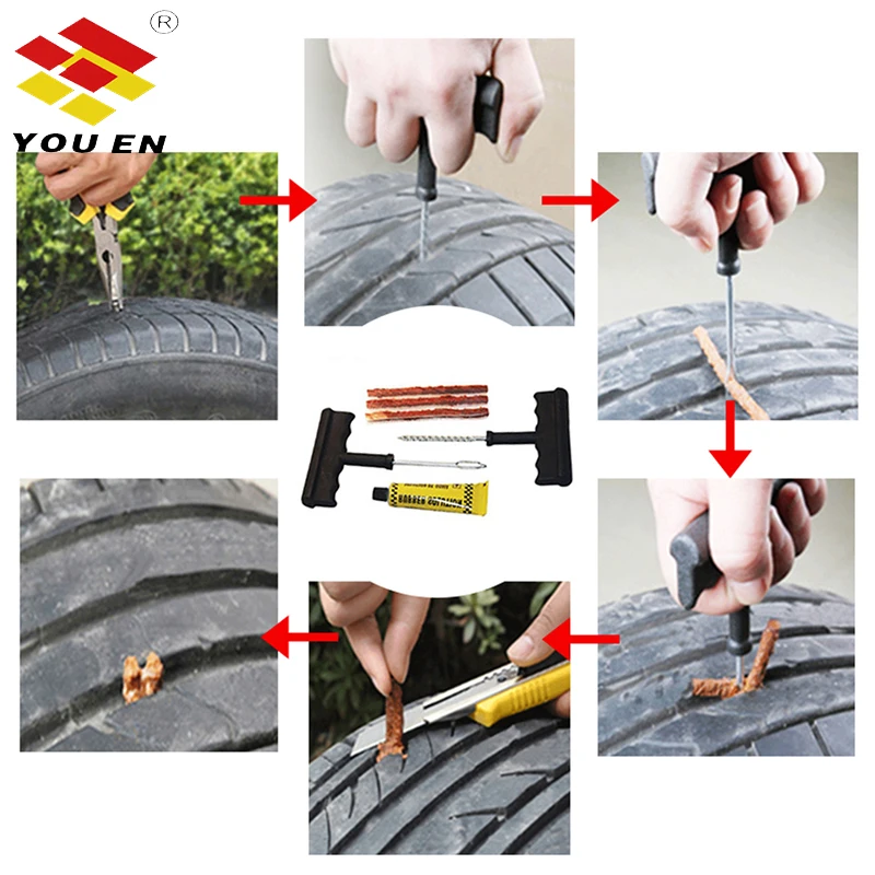
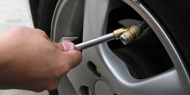
Locate the puncture. If you don’t see or hear the puncture, spray some soapy water on the tire and look for bubbles.
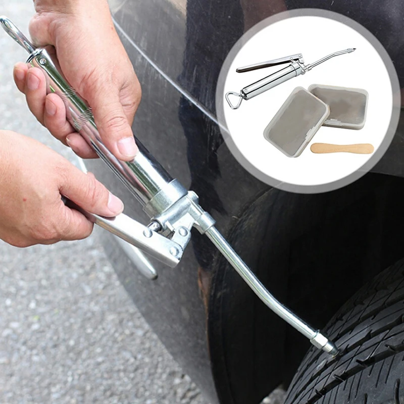
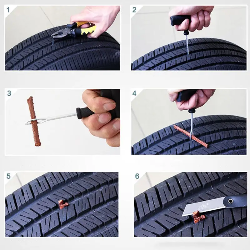
This is a small staple that was dropping tire pressure by 20 psi in about 12 hours. It needs to go.Remove the offending item. This is usually easy, but sometimes the nail or screw is worn down, making it hard to get a bite on it. This is where the side-cutters come in really handy. You will want to position the tire where you get the most leverage.
Side cutters work best for removing these items, as they can grip small round objects better than regular pliers.Insert the reamer. This will take some effort, as you have to push it through the steel belts. Use a twisting motion and push it into the tire. Once the reamer is through, saw it in and out of the tire a few times to really make a nice hole for the plug. Yes, it is counter-intuitive, but it is necessary.
Push the reamer all the way and then saw it in and out a few times to make a clean hole.
Prep the plug and installer. Pull a plug off the strip and push it through the eyelet of the installer tool. The pliers will make this easier. Push a little through, grab it with the pliers and pull the plug halfway through the eyelet.
Pull a cork strip from the tire plugging kit and grab the installer tool, which looks like a large needle with a slit in the eye.Threading the sticky cork tire repair plug is not easy, but if you can get it squished into the hole, you should be able to pull it on through.
 The side cutters might help.
Insert the plug into the tire. If the kit has liquid cement, apply some to the plug before inserting it into the tire. Simply push the installer into the hole in the tire until the plug is about 3/4 of the way in. Twist the installer tool 90-degrees and pull it out. The plug will stay in the tire and the tool will come out nice and easy. You may trim away the excess plug or leave it to wear away as you drive.
Push the tire plug into the hole. Don’t twist the plug as you push it in, just go straight down and stop when there is about a 1/2-inch exposed.This is what you should see when the tire plug is installed.
Once the tire repair plug is in you can now twist the handle 90-degrees and pull the tool out.
Fill the tire to the proper PSI. If you have a portable air compressor, this will make things easy. However, if you do not, you need to get air very soon.
All done. You can trim the tire plug or leave. You will need air, so don’t go driving until you have the tire aired up.
Every automobile you own should have an emergency tire plug repair kit in the tool box, along with a portable air compressor. These emergency repairs are quite good, but for a long term repair, you should take the vehicle to a tire shop for a proper repair as soon as possible. They will know the best way to patch a tire for your type of damage.
Check out all the steering & suspension parts
Categories
Know How
Tags
emergency repair, flat tire, flat tire repair, patch flat tires, sealant, tire maintenance, tire plug kit, tire pressure, tire safety, tire wear, tires, wheels
A life-long gearhead, Jefferson Bryant spends more time in the shop than anywhere else. His career began in the car audio industry as a shop manager, eventually working his way into a position at Rockford Fosgate as a product designer. In 2003, he began writing tech articles for magazines, and has been working as an automotive journalist ever since. His work has been featured in Car Craft, Hot Rod, Rod & Custom, Truckin’, Mopar Muscle, and many more. Jefferson has also written 4 books and produced countless videos. Jefferson operates Red Dirt Rodz, his personal garage studio, where all of his magazine articles and tech videos are produced.
Every editorial product is independently selected, though we may be compensated or receive an affiliate commission if you buy something through our links. Ratings and prices are accurate and items are in stock as of time of publication.
Modern vehicle tires are tough, standing up well to rough terrain and thousands of miles of driving. Trouble is, tires are not invincible. Every so often car tires spring leaks. Air can start leaking from anywhere on a tire, and the location of the leak determines whether or not you can fix it yourself. And if you can't fix it yourself, the location of the leak will also tell you if you need a professional repair or a new tire.
Whether or not your tire is tubed or tubeless affects things, too, because only tubeless tires can be repaired using the technique of plugging that we'll show you here. The good news is that modern vehicles always have tubeless tires, and this means that repairing with a rubber plug is often an option.
Plugging a tubeless tire is only a possibility when your puncture is in the tread area. If the air leak is where the sidewall of the tire meets the rim — this is called a "bead leak" — you'll need to visit a mechanic with a tire machine to dismount the tire from the rim and remount it with sealing liquid applied to the bead.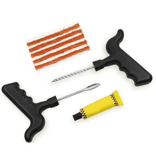 If your sidewall has been punctured, you need a new tire, because damage there can lead to a blowout at highway speeds, even after repair.
Learn exactly how to plug a tire so next time you spring a leak between your treads, you'll be able to get up and running again in record time.
Total time completing the repair is about 15 minutes. Doing the work yourself will save you about $20 and the time spent driving to the garage and waiting.

Steve Maxwell for Family Handyman
Complete DIY projects like a pro! Sign up for our newsletter!
Do It Right, Do It Yourself!
Originally Published: August 27, 2020
%PDF-1.5 % 10 obj > /Metadata 2 0 R /Pages 3 0 R /StructTreeRoot 4 0 R /Type /Catalog >> endobj 5 0 obj /ModDate (D:20170613132857+02'00') /producer /Title >> endobj 20 obj > stream
 44 841.68] /Parent 3 0R /resources> /ProcSet [/PDF /Text /ImageB /ImageC /ImageI] /XObject> >> /Rotate 0 /StructParents 0 /Tabs /S /Type /Page >> endobj 80 obj > /MediaBox[0 0 595.44 841.68] /Parent 3 0R /resources> /ProcSet [/PDF /Text /ImageB /ImageC /ImageI] >> /Rotate 0 /StructParents 1 /Tabs /S /Type /Page >> endobj 9 0 obj > /MediaBox [0 0 595.44 841.68] /Parent 3 0R /resources> /ProcSet [/PDF /Text /ImageB /ImageC /ImageI] >> /Rotate 0 /StructParents 2 /Tabs /S /Type /Page >> endobj 10 0 obj > /MediaBox [0 0 595.44 841.68] /Parent 3 0R /resources> /Font> /ProcSet [/PDF /Text /ImageB /ImageC /ImageI] >> /Rotate 0 /StructParents 3 /Tabs /S /Type /Page >> endobj 11 0 obj > /MediaBox[0 0 595.44 841.68] /Parent 3 0R /resources> /Font> /ProcSet [/PDF /Text /ImageB /ImageC /ImageI] >> /Rotate 0 /StructParents 4 /Tabs /S /Type /Page >> endobj 12 0 obj > /MediaBox [0 0 595.44 841.68] /Parent 3 0R /resources> /Font> /ProcSet [/PDF /Text /ImageB /ImageC /ImageI] >> /Rotate 0 /StructParents 5 /Tabs /S /Type /Page >> endobj 13 0 obj > /MediaBox [0 0 595.
 44 841.68] /Parent 3 0R /resources> /Font> /ProcSet [/PDF /Text /ImageB /ImageC /ImageI] >> /Rotate 0 /StructParents 6 /Tabs /S /Type /Page >> endobj 14 0 obj > /MediaBox[0 0 595.44 841.68] /Parent 3 0R /resources> /ProcSet [/PDF /Text /ImageB /ImageC /ImageI] >> /Rotate 0 /StructParents 7 /Tabs /S /Type /Page >> endobj 15 0 obj > /MediaBox [0 0 595.44 841.68] /Parent 3 0R /resources> /ProcSet [/PDF /Text /ImageB /ImageC /ImageI] >> /Rotate 0 /StructParents 8 /Tabs /S /Type /Page >> endobj 16 0 obj > /MediaBox [0 0 595.44 841.68] /Parent 3 0R /resources> /ProcSet [/PDF /Text /ImageB /ImageC /ImageI] >> /Rotate 0 /StructParents 9/Tabs /S /Type /Page >> endobj 17 0 obj > /MediaBox [0 0 595.44 841.68] /Parent 3 0R /resources> /ProcSet [/PDF /Text /ImageB /ImageC /ImageI] >> /Rotate 0 /StructParents 10 /Tabs /S /Type /Page >> endobj 18 0 obj > /MediaBox [0 0 595.44 841.68] /Parent 3 0R /resources> /ProcSet [/PDF /Text /ImageB /ImageC /ImageI] >> /Rotate 0 /StructParents 11 /Tabs /S /Type /Page >> endobj 19 0 obj > /MediaBox [0 0 595.
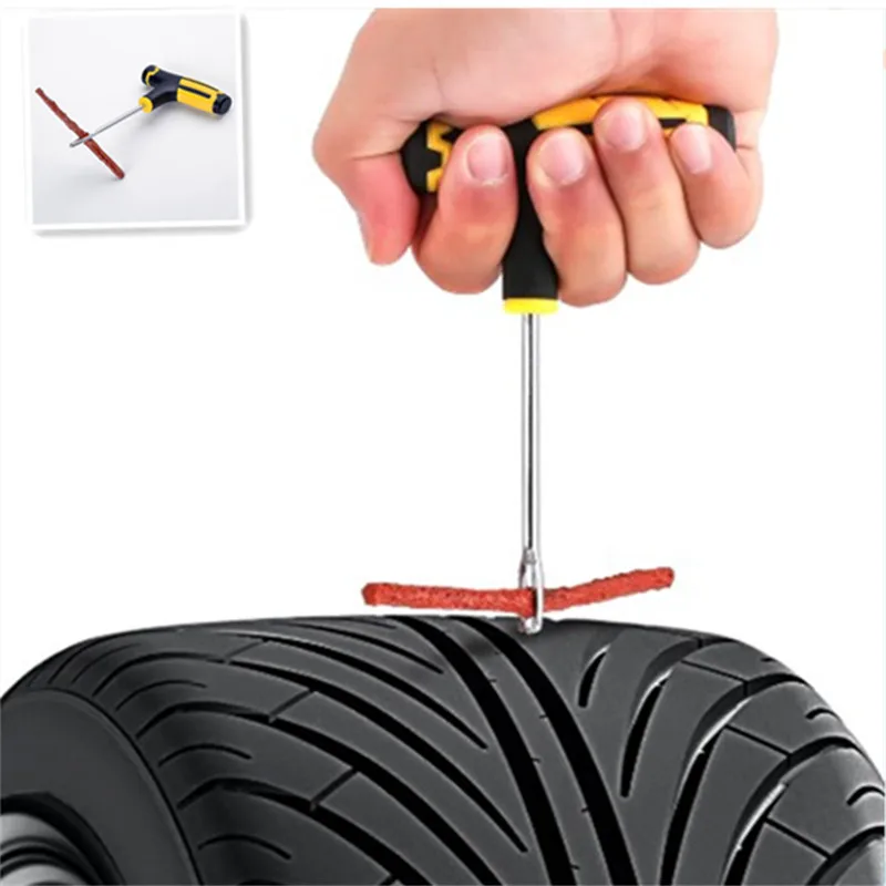 44 841.68] /Parent 3 0R /resources> /Font> /ProcSet [/PDF /Text /ImageB /ImageC /ImageI] >> /Rotate 0 /StructParents 12 /Tabs /S /Type /Page >> endobj 20 0 obj > /MediaBox[0 0 595.44 841.68] /Parent 3 0R /resources> /ProcSet [/PDF /Text /ImageB /ImageC /ImageI] >> /Rotate 0 /StructParents 13 /Tabs /S /Type /Page >> endobj 21 0 obj > /MediaBox [0 0 595.44 841.68] /Parent 3 0R /resources> /ProcSet [/PDF /Text /ImageB /ImageC /ImageI] >> /Rotate 0 /StructParents 14 /Tabs /S /Type /Page >> endobj 22 0 obj > /MediaBox [0 0 595.44 841.68] /Parent 3 0R /resources> /ProcSet [/PDF /Text /ImageB /ImageC /ImageI] >> /Rotate 0 /StructParents 15 /Tabs /S /Type /Page >> endobj 23 0 obj > /MediaBox[0 0 595.44 841.68] /Parent 3 0R /resources> /ProcSet [/PDF /Text /ImageB /ImageC /ImageI] >> /Rotate 0 /StructParents 16 /Tabs /S /Type /Page >> endobj 24 0 obj > /MediaBox [0 0 595.44 841.68] /Parent 3 0R /resources> /ProcSet [/PDF /Text /ImageB /ImageC /ImageI] /XObject> >> /Rotate 0 /StructParents 18 /Tabs /S /Type /Page >> endobj 25 0 obj > /MediaBox [0 0 595.
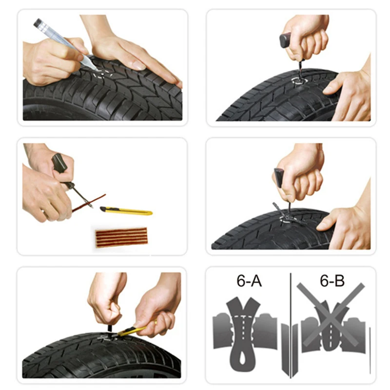 44 841.68] /Parent 3 0R /resources> /ProcSet [/PDF /Text /ImageB /ImageC /ImageI] /XObject> >> /Rotate 0 /StructParents 19/Tabs /S /Type /Page >> endobj 26 0 obj > /MediaBox [0 0 595.44 841.68] /Parent 3 0R /resources> /ProcSet [/PDF /Text /ImageB /ImageC /ImageI] /XObject> >> /Rotate 0 /StructParents 20 /Tabs /S /Type /Page >> endobj 27 0 obj > /MediaBox [0 0 595.44 841.68] /Parent 3 0R /resources> /Font> /ProcSet [/PDF /Text /ImageB /ImageC /ImageI] /XObject> >> /Rotate 0 /StructParents 21 /Tabs /S /Type /Page >> endobj 28 0 obj > /MediaBox [0 0 595.44 841.68] /Parent 3 0R /resources> /Font> /ProcSet [/PDF /Text /ImageB /ImageC /ImageI] /XObject> >> /Rotate 0 /StructParents 22 /Tabs /S /Type /Page >> endobj 290 obj > /MediaBox [0 0 595.44 841.68] /Parent 3 0R /resources> /Font> /ProcSet [/PDF /Text /ImageB /ImageC /ImageI] /XObject> >> /Rotate 0 /StructParents 23 /Tabs /S /Type /Page >> endobj 30 0 obj > /MediaBox [0 0 595.44 841.68] /Parent 3 0R /resources> /Font> /ProcSet [/PDF /Text /ImageB /ImageC /ImageI] /XObject> >> /Rotate 0 /StructParents 24 /Tabs /S /Type /Page >> endobj 31 0 obj > /MediaBox [0 0 595.
 44 841.68] /Parent 3 0R /resources> /Font> /ProcSet [/PDF /Text /ImageB /ImageC /ImageI] /XObject> >> /Rotate 0 /StructParents 25 /Tabs /S /Type /Page >> endobj 32 0 obj > /MediaBox[0 0 59
 Expand
| Tool name | Number |
| Power drill | 2 |
| Electric drill | 1 |
| Cordless screwdriver | 1 |
| Electric angle cutter | 1 |
| SDS adapter with keyless chuck | 2 |
| Riveting gun | 2 |
| Construction level bar 1.5m | 1 |
| Toolbox | 2 |
| Bench hammer 400 gr | 2 |
| Sledgehammer | 1 |
| Percussion tool set (chisel, bolt, punch, center punch) | 1 |
| Hacksaw | 1 |
| Metal shears | 1 |
| Pliers | 1 |
| Side cutter medium | 1 |
| File set | 1 |
| Carbide screwdriver set | 1 |
| Wrench set | 1 |
| Universal ladder 4-fold | 1 |
| 3-section universal ladder (more than 6m) | 1 |
| Silicone gun | 1 |
| Tester | 1 |
| Electric soldering iron 60 W | 1 |
Electric extension cord min.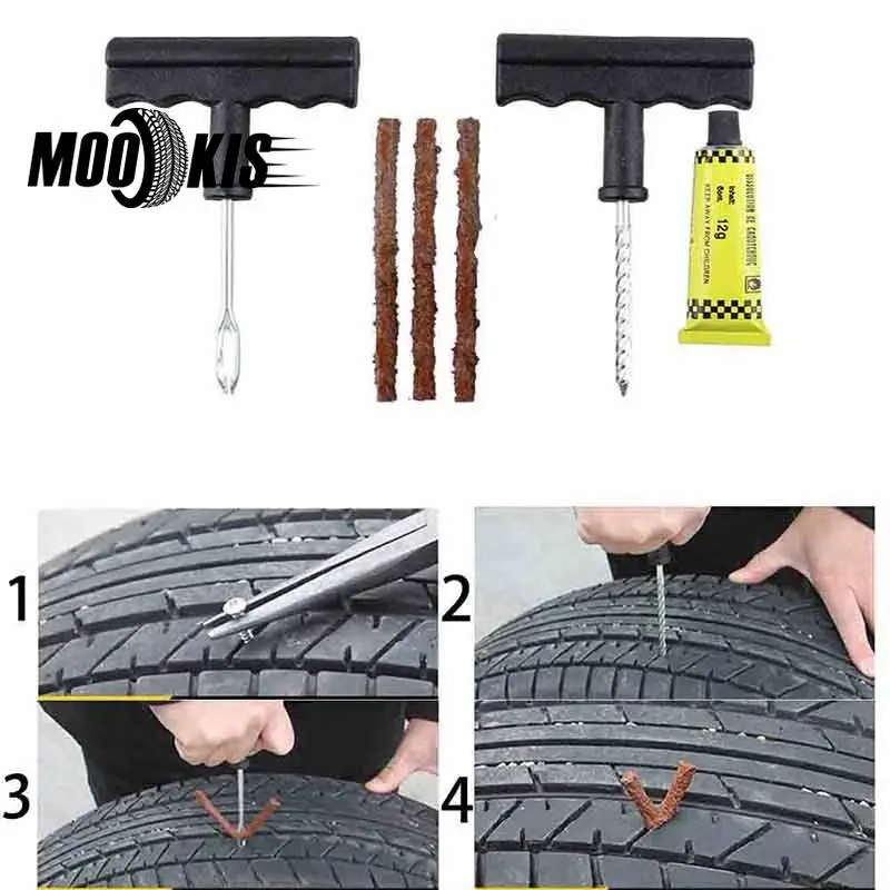 30 m 30 m | 1 |
| Electric screwdriver indicator | 1 |
| Tape measure 5 m | 1 |
| Caliper 125 mm | 1 |
| Goggles | 2 |
| Construction helmet | 3 |
| Universal first aid kit | 1 |
| Standard drill set for metal | 1 |
| Concrete drill O 6 mm L=160-200 mm | 2 |
| Concrete drill O 8 mm L=200-260 mm | 2 |
| Concrete drill O 10 mm L=550 mm | 2 |
| Concrete drill O 12 mm L=550 mm | 2 |
| Concrete drill O 14 mm L=750 mm | 2 |
| Concrete drill O 16 mm L=950 mm | 1 |
| Concrete drill O 18 mm L=550 mm | 1 |
| Concrete drill O 20 mm L=550 mm | 1 |
| Note: The recommended number of assembly team - 3 people: electrician - 1 person, fitter - 2 people. 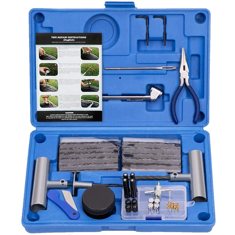 | |
Before proceeding with the installation of the roller shutter, it is necessary to check that the complete set is complete.
The surface where the guide rails and the protective box will be installed must be even and smooth, without cracks and sagging from the plaster.
fig.1 Surface mounting.
For surface mounting, it is necessary to take the guide rails and attach them to each other with blind sides. Mark the places for fastening with a marker, the distance between the fasteners is approximately 450-550 mm, the upper and lower fasteners should be located at a distance of 100-150 mm from the tire cuts. Drill holes Ø12 mm for subsequent installation of plugs.
Note: do not drill through the bar!!!
fig.2 Built-in installation.
For recessed mounting, lay the busbars edgewise and drill the holes in the stiffener at the same distance as for surface mounting, using the same spacing of 450-500mm between the holes, with a Ø 12mm drill.
Note: Do not drill through the bar!!!
fig. 3 Surface mounting.
fig.4 Built-in installation.
Note: action (fig. 5) for outdoor mounting for the output of cardan, tape, cord, cord or electric drive wire.
fig.5
The next step is to fit the two guides into the side covers, and insert the guide rails into the legs of the side covers (fig.6).
fig.6
Apply to the frame of the opening.
fig.7
Install inside the opening.
fig.8
Roller shutter frame must be level. The guide rails and the protective box of the roller shutter must fit snugly against the plane of the opening along the entire height and width.
Valid for surface-mounted structures.
fig.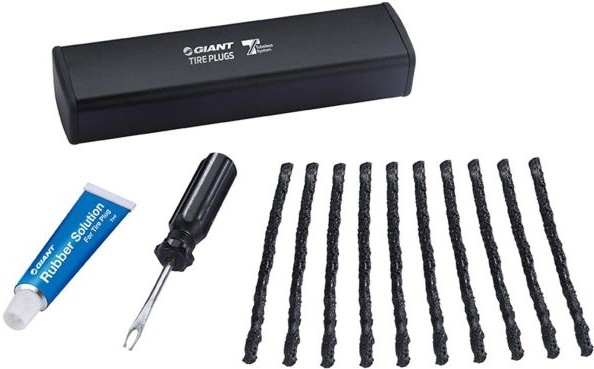 9
9
After leveling the structure, mark the location of the hole for further output of the controls:
In the drilled hole, install the safety spring for the cord or the tube (Fig. 10) for the cord.
fig. 10
fig. 12
Remove the protective film from the roller shutter box and place the frame in place. It is recommended to drill holes for installing dowels with a long drill to avoid damage to the roller shutter elements.
When carrying out fastening, it is necessary to periodically check the correct installation using the mounting level.
The frame must be securely fastened and not pose a potential hazard to human health and life. For fasteners, it is forbidden to use silicone, wooden plugs or mounting foam.
When installing a roller shutter with an electric drive, it is necessary to connect the cable to the switch terminals in accordance with the instructions for connecting the roller shutter motor.
When installing a mechanical type of roller shutter drive - thread the tape, cord or cord into the guides.
fig. 13
fig. 14
Insert the motor cable or tape into the previously drilled hole in the wall (surface mounting). The cord cable or cord must be threaded into the safety spring or tube and secured.
Attach drive mechanisms: cardan, cord, cord or belt.
fig. 15
fig. 16
In case of built-in installation, the drive mechanisms are fastened to the guide rail using self-tapping screws or rivets.
Installing the curtain must be led behind the shaft from the rear of the protective box into the guide rails (Fig. 17). To avoid damage to the blade coating, wrap the roller with a rag.
fig. 17
When mounting a roller shutter with mechanical drives, attach a cord, tape or cord to the pulley (Fig. 18). By rotating the shaft, wind the traction element on the pulley to further control the web.
fig. 18
The next step is to fasten the roller shutter leaf with the suspension mechanism (Fig. 19, 20) (crossbars or traction springs). Lead them from the side into the upper lamella of the canvas.
fig. 19
fig. 20
Place the locking bolt on the shaft and fix it with the bolt rings, bring the rings together until they stop. The crossbar must fall into the mounting holes of the rings. In this position, the rings must be fixed with self-tapping screws. It is not necessary to drill the shaft, it is not necessary to install the self-tapping screw, the self-tapping screw is installed in the hole of the crossbar ring and is screwed all the way into the wall of the shaft.
fig.21
fig. 22
Traction spring is attached to the shaft perforations. It is necessary to compress the end of the traction spring and insert it into the shaft.
fig. 23
To limit the lifting of the curtain, you need to install a stopper in the bottom bar. Drill through holes in the end plate at a distance of 50-100 mm from the guide rails. Install a locking bolt through the lining into the holes and screw the stopper to it.
fig. 24
For the design with PIM (spring-inertial mechanism) after installing the curtain in the guide rails, and installing the traction springs, it is necessary to tighten the spring installed in the shaft, rotating the shaft away from you (if the open part of the box looks at you) . While holding the shaft, install the traction springs in the perforations of the shaft.
Hold the blade by the stopper to check the operation of the PIM.
If necessary, increase or decrease the number of spring turns.
fig. 25
Guided by the instructions for connecting the electric drive, connect to the network and adjust the end positions of the roller shutter leaf.
Install the protective cover of the box into the groove and fix it with rivets or self-tapping screws.