by Gerald Newton
revised January 26, 2006
During the last 60 years electricians have used offset bending tables published by Jack Benfield. Jack Benfield was a salesman during the late 1930's who had the task of selling EMT to the electrical industry. At that time, one reason for not accepting EMT was the difficulty with bending the tubing. Benfield solved this problem by inventing the Benfield Bender and simplifying the mathematics of bending offsets into simple rules and tables of multipliers avoiding the use of trigonometry. Today these tables are published in just about every handbook and manual on conduit bending and are found in the 2 million books sold as the Benfield Conduit Bending Manual. In his book just below one of his famous Zip Guides on page 12 Jack Benfield states, "The Benfield technique works for all sizes of EMT, rigid conduit, or IMC. The same formulas can be used with power benders on 6 inch conduit.
..it also works for any make of bender that may be found on any job." The author disagrees with this statement and will tell you why in the following presentation.
The Benfield method over simplifies the bending of offsets by using approximations that have built in errors that increase with the size of pipe, the dimension of the radius, and the steepness of the bend. In fact the author discovered that the Benfield rule of using the cosecant of the angle to multiply times the height of the offset to find the distance between bends (where his table values came from) assumes the pipe has no bends or arcs at all but follows a broken straight line path. The Benfield shrinkage multipliers are constant when in fact the shrinkage and shrinkage multiplier are a function of the centerline bending radius.
These errors have caused the author untold misery over the years resulting in rebending of pipe, banging the pipe on the floor to remove degrees of bend, recutting precut pipe, and sometimes discarding the offset bent pipe entirely. It is a very frustrating task indeed to make every effort to bend an offset to 1/16 of an inch only to find that even with your utmost care in using the Benfield Tables and method that your pipe is anywhere from 3/8 to 2 inches off. What is even more frustrating is thinking that you were the problem and not knowing that the Benfield Tables were the root cause. After all, if these tables have been published for over 60 years and are attached to hand bender handles by manufacturers they must be correct. However, as we shall see, this is not the case.
After developing and installing the equations found in Figures 1 and 2 in an Excel spreadsheet and a JavaScript computer program and evaluating and testing the results, they reveal that, indeed, the Benfield Tables are approximations, the best fit of the least squares or something like that. How can a 1/2 inch bender and a 2, and 4 inch bender all have the same table when they have different bending radii? They don't and that is why those shrinkage values always come out just a little off and become more off as the size of the raceway increases. But with long necked connectors for EMT the errors do not cause too many problems for 1/2, 3/4, and 1 inch EMT for bends up to 30 degrees. But if you use the Benfield Tables and technique for bends over 30 degrees or on 1 1/4 to 6 inch pipe, you are going to have trouble!
The center line bend radii for pipe sizes from 1/2 inch to 5 inches for 71 benders were entered into an Excel spread sheet and used in the calculation of shrinkage and distance between bends and this was compared to the calculated numbers using the Benfield offset formulae given on page 8 of the Benfield Conduit Bending Manual for 10 degrees, 22 1/2 degrees, 30 degrees, 45 degrees, and 60 degrees The spreadsheet performed 3,552 calculations to reveal the following. The errors in shrinkage for a 30 inch high offset varied from 5/16 of an inch for 1/2 inch EMT with a 22.5 degree offset to 3 1/16 inch for 5 inch rigid with a 60 degree offset. The errors in distance between bends for a 30 inch high offset varied from 1/16 of an inch for 1/2 inch EMT with a 30 degree offset to 4 inches for 5 inch rigid pipe with a 60 degree offset. In 11 cases using the Benfield shrinkage values would result in precutting the pipe up to 3 1/16 inches too short. The average error for shrinkage is 9/16 inches and the average error for distance between bends is 2 inches. The results of these calculations and for other offset heights are so overwhelming that the author recommends using the Benfield offset formulae only for 1/2 inch to 3/4 inch EMT with bends no greater than 30 degrees. The offset error Excel spreadsheet showing these calculations is available by clicking here.
Performing trigonometric calculations in the 1930's and until the late 1960's was a time consuming task requiring slide rules, trigonometric tables, and hand written calculations. In the late 1960's the computer revolution began. Today, desktop and laptop computers are found on almost every electrical job and most electricians are computer literate. Today, Performing complex trigonometric calculations is as simple as clicking on a button in a web page. The author has evaluated the Benfield tables and methods in order to find if computers can be used to bend more accurate offsets, and has written a web page calculator that performs mathematically correct calculations.
The offset calculator that uses the mathematics developed in Figures 1 and 2 is below. There are several other offset calculators on the internet that use the Benfield Tables to calculate shrinkage and distance between bends. These calculators give the same errors as the original Benfield Tables and method. If you are going to use an offset bender computer program make sure it uses the centerline bend radius and the length of the arc in the program, or better just go to http://www.electrician2.com and find the Offset Bend Calculator under the menu item "calculators."
Figure 1
Figure 2
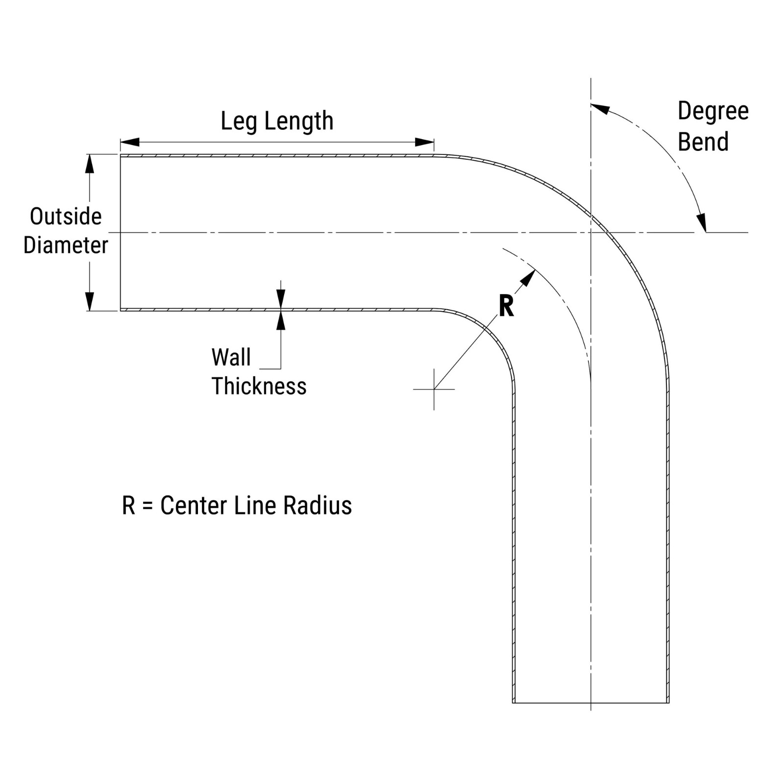
Why Use the Centerline Radius?
The reason that the centerline radius is used in the calculation is because when a pipe is bent the inside radius shortens from its original length and the outside radius lengthens from its original length, but the centerline radius stays the same length before and after bending. In Figure 3 a blue tape was placed one foot from the end of a 3/4 EMT. Then three wires were cut exactly one foot long. The EMT was bent into a 90 degree bend using a hand bender. The wires were then attached to the pipe, one at the inside radius, one at the centerline radius, and one at the outside radius. The calculated difference between the inside radius and the outside radius is 1.45 inches. As seen in Figure 3 that is the difference found. However, the centerline radius did not increase or stretch in length. Therefore the centerline arc distance represents the original length of conduit from which the arc was created.
Figure 3
Straight Pipe Length
The straight pipe length is the length of PP' in figure 1. This length is entered in the calculator as a reference. When the calculation is performed the calculated straight pipe length is compared to the entered value and if it is less an alert window warns the user. Straight pipe lengths of 2 to 3 inches are recommended for small hand benders. For larger pipes and other types of benders 1/2 the radius distance should always be a safe distance that will allow the two bends to be made. However, this has not been verified in the field using all types of benders. A negative straight pipe length means the two arcs are extending into each other and should be avoided. To increase the Straight Pipe Length decrease the angle of bend. This will also cause the distance between bends to be greater.
Straight Pipe Length = P'P in Figure 1.
Distance Between Bends
The distance between bends found by multiplying the height of the offset by the cosecant of the angle is a method given in many popular handbooks, manuals, and references. This is where the multipliers of 6 for 10 degrees, 2.6 for 22.5 degrees, 2.0 for 30 degrees, 1.4 for 45 degrees, and 1.2 for 60 degrees come from. This method is an approximation and is not mathematically correct, because it does not use the length of the arc of the bend. For most offsets of up to 30 degrees, there is little difference in using this method or using the correct mathematical calculation. However, again for greater angles and large pipe these multipliers will give you errors that may require recutting the pipe and/or altering the bend angles. I have placed the correct calculation in the offset calculator and added a conversion for decimal to the nearest 16th of an inch in fractions.
Distance Between Bends = (angle of bend / 360) X 2 x Pi x radius + P'P as shown in Figures 1 and 2.
An illustration of using the cosecant of an angle as a multiplier when it causes a significant error can be readily understood when we consider a 90 degree offset, 90 degree being the maximum bend angle that we would probably ever use. The cosecant of 90 degrees is 1. Let's find the distance between bends for a 60 inch high offset using a 4 inch pipe with a 20 inch center line bend radius. Using the cosecant the distance between bends would be the cosecant (90 degrees) x 60 or 60 inches. If we made two 90 degree bends at 60 inches apart that should give us a 60 inch offset if the cosecant is the correct multiplier. However, the calculator says the distance between bends should be 51 7/16 inches and the multiplier is 0.857. Using the cosecant as a multiplier would make our offset 60 - 51 7/16 or 8 9/16 inches too high. We would end up with a 68 9/16 inch high offset! Why the difference? The cosecant multiplier assumes that there are no curves or arcs in the bends and that the pipe follows a broken line path, and it would have to for two 90 degree bends 60 inches apart to give us a 60 inch height. The calculator applies the correct math to the curves or arcs of the bends and compensates for the gain they add to the 90 degree bend or, for that matter, any bend. If we enter a 20 inch radius and a 90 degree bend into the Developed Length Calculator we find that the gain or shrink is 8 9/16 inches.
Using the cosecant as a multiplier for angles of 10, 15, 20 and 30 degrees is a good approximation, but with computers doing the work, we can be more precise. When you think of it, today almost every job has a desktop computer that is equivalent to what was a mainframe computer costing hundreds of thousands of dollars forty years ago. We now have these powerful tools readily available so why not use them?
Field Test Results:
Example 1
Here are actual test results from using the calculator and the cosecant of the angle to bend a 15 inch 90 degree offset using 3/4 inch EMT and an Ideal 3/4 inch hand bender with a 5.2 inch centerline radius (remember the cosecant of 90 degrees is 1):
| Calculator | Using the cosecant of the angle | |
| Distance Between Bends | 12 3/4 inches | 15 inches inches (1 x 15 = 15 inches) |
| Measured Offset Ht after bending | 15 inches | 17 1/2 inches |
| Calculated Shrinkage | 10 9/16 inches | No multiplier listed (.82 by calculation) |
| Measured Shrinkage | 10 1/2 inches | 12 3/8 inches |
Table 1
The calculator wins, hands down!
Although making a 90 degree offset is unusual, the calculator values can be used to make a back to back 90's or for that matter any situation where the second 90 degree bend is not in the same plane as the first 90. Don't try this using the cosecant of 90 degrees as a multiplier!
Example 2
Here is another example using the calculator against the Zip Table values published in the Benfield Conduit Bending Manual that are shown in Table 3 A 7 inch height, 60 degree offset was made using both methods using 3/4 EMT and an Ideal 3/4 inch EMT hand bender with a 5.2 inch centerline radius. Here is a Table of the results (remember the cosecant of 60 degrees is 1.2):
| Calculator | Zip Table | |
| Distance Between Bends | 7 1/2 inches | 8 3/8 inches (1.2 x 7 = 8.4 inches) |
| Measured Offset Ht after bending | 7 inches | 7 5/8 inches |
| Calculated Shrinkage | 2 15/16 inches | 3 1/2 inches (0.5 x 7 = 3 1/2) |
| Measured Shrinkage | 2 7/8 inches | 3 1/8 inches |
Table 2
The results are overwhelming. The calculator again wins hands down.
Shrink for any Bend
Shrink = 2 x radius x (tan (bend angle / 2)) - Developed Length
Developed Length is found by:
Developed Length = (angle of bend / 360) x 2 x Pi x radius
For 90 degrees the developed length is the familiar 1.57 x radius that is derived from 90/360 x Pi x Diameter, where diameter is equal to 2 x radius.
Since the tan of 45 degrees is 1, the Shrink for a 90 degree bend is (2 x radius) - (1.57 x radius)
When Shrink is used to bend and cut pipe, one must remember that the shrink is derived using the centerline radius, not the outside radius. Field measurements taken using the back side of a conduit can result in errors.
Here is a typical Table from a handbook from which the Table values were used:
| in Degrees (Angle) | | Multiplier in inches |
| | | |
| |  9 9 | |
| | | |
| | | |
| | | |
| | | |
Table 3
Calculator by electrician2.com |
| |||||
| go next page |
References:
| | | | | | | |
| Site-Rite Hand Bender | | | | | ||
| Site-Rite II Hand Bender | | | | | ||
| 555 EMT | | | | | | |
| 555 IMC | 4-3/8" | 4-1/2" | 5-3/4" | 7-1/4" | | |
| 555 Rigid | | | | | | |
| 854 / 855 EMT | | | | | | |
| 854 / 855 IMC/Rigid | | | | | | |
| 880 | | | | | | |
| 882 EMT | | | | | | |
| 882 IMC / Rigid | | | | | | |
| 1800 / 1801 Rigid & IMC | | | | | |
| | | | | | | | | |
| 777 | | | | | | | | |
| 881 | | | | | ||||
| 884 / 885 | | | | | | | | |
| |  0625 0625 |
| | |
| | |
| | |
| | |
| | |
| | |
| | |
| | |
| | |
Trade Size in Inches | Outside Dia. in Inches | Inside Dia. in Inches in Inches | Wall Thickness in Inches |
| | | | |
| | | | |
| | | | |
| | | | |
| | | | |
| | | | |
| |  875 875 | | |
| | | | |
| | | | |
| | | | |
| | | | |
| |
Trade Size in inches | Outside Dia. in Inches | Inside Dia in Inches | Wall thickness in Inches |
| |  840 840 | | |
| | | | |
| | | | |
| | | | |
| | | | |
| | | | |
| | | | |
| | |  090 090 | |
| | | | |
| | | | |
| | | | |
| |
Trade Size in Inches | Outside Dia. in Inches | Inside Dia. in Inches | Wall Thickness in Inches |
| |  815 815 | | |
| | | | |
| | | | |
| | | | |
| | | | |
| | | | |
| | | | |
| | |  216 216 | |
| | | | |
| | | | |
| | | | |
| |
SHARE THIS:
This is, no-doubt, my most asked for topic to do an episode. “Do an episode on bending conduit” they say….”It’ll be fun” they say… Well my friends, strap in, here we go….
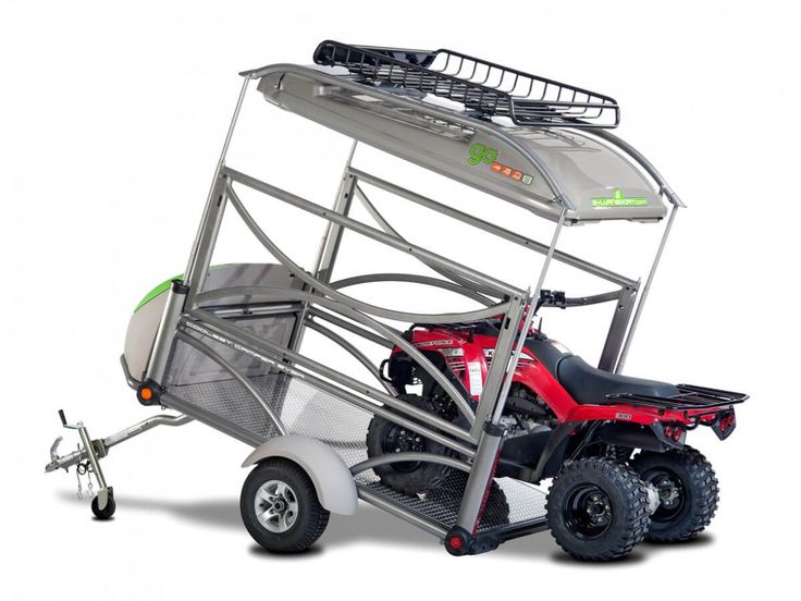
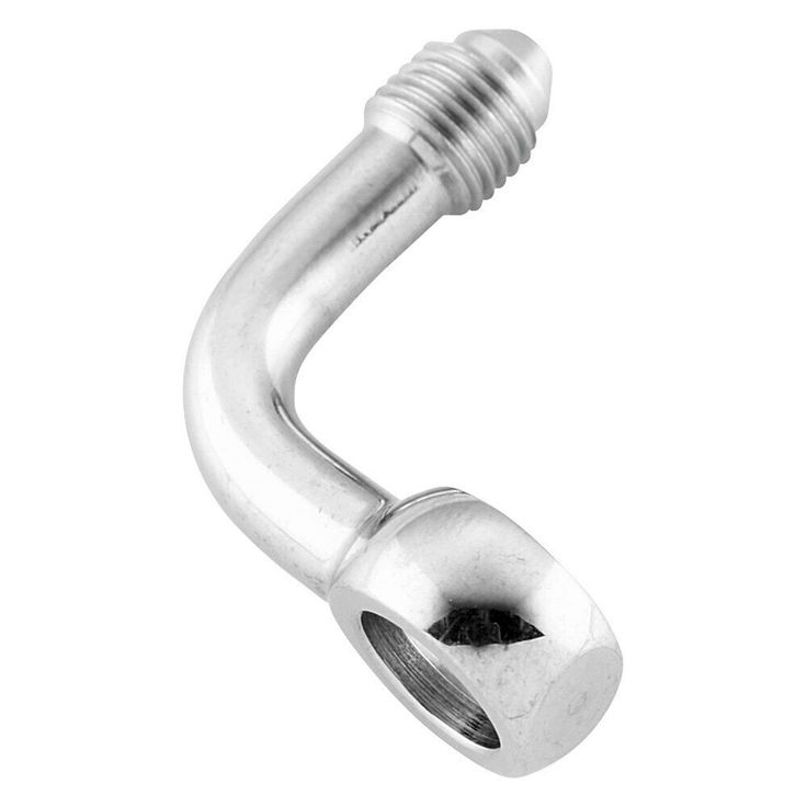
First off there are some things to understand about different types of conduits. For example today we’re going to be bending EMT (Electrical Metallic Tubing). This type of conduit is relatively easy to bend using a bender if you’re bending 1/2”, 3/4”, or 1”. Once you get to about 1 1/4” and up this type of conduit requires a larger bender, and a lot of ass behind the person bending it. Normally in this situation a company will use a “Chicago Bender” or an “Machine Bender” (which is normally either electric, pneumatic, hydraulic) See below:
In our example we’re going to be dealing with 1/2”, 3/4”, and 1” EMT. This is the easiest conduit to bend, so for those of you practicing at home – choose 1/2” EMT to start with before moving up to 3/4” or 1” as the ease of use makes the understanding go further.
First thing we talk about is understanding the bender. There are tons of little lines, marks, and numbers on the shoe of a conduit bender, and knowing which one does what is half the battle. To start off, every bender has stamped in it what type of conduit the bender is designed to be used for. A 1/2” bender will say “1/2” EMT Only” or something similar – usually located where the shoe meets the threaded end of the handle. If you flip the bender around 180 degrees, in the same spot there will be a stamp for what size takeoff you’ll need to use to achieve the proper bend with this bender.
Next are the lines that say 10, 22.5, 30, 45, and 60 next to them. These are your angles of bend radius. To bend a 30 degree angle with a conduit bender, you bend the pipe up from the ground until the 30 degree line on the bender is parallel to the pipe and floor. You would flip the bender over and repeat this step if you were trying to bend a 30 degree offset to overcome an obstacle.
Probably the most important mark to learn is the “arrow” – this is the marker you’ll use most often when bending 90’s or offsets. If you need to bend a 90 or offset at 65” you’ll mark your pipe and line the arrow up with the mark, and bend accordingly.
Next is the “star” notch. The star is normally set along the same axis as the handle of the bender, and if you follow the bender from the handle all the way to the top of the shoe you’ll notice that this star notch is at the top dead center of the bender. You would use this star notch for bending a “backward 90” rather than doing a takeoff and using the arrow for a “forward 90”
The last mark we’ll talk about in this article is the “saddle” notch between the star and the arrow. Some benders will actually mark this with a half-circle around it, some do not mark it at all. The purpose of this notch is to mark the middle of a saddle bend, if you’re bending a 3-point saddle.
A forward 90 is a 90 degree bend made by measuring from the front side of a pipe (front being the side you’re looking at if you’re kneeling at the half way point of the pipe. The part of the pipe behind you is called the “back side” of the pipe. With a forward 90 you take a measurement from the end of the pipe and mark that measurement. If you need to bend a 90 to hit a wall or some arbitrary line, you’ll use this exact measurement to mark your pipe. From this measurement you’ll subtract whatever amount you need (depending on the size of the pipe) towards the end of the pipe you just measured from. So from your original mark you measure, AWAY FROM YOU, 6 inches with 3/4” EMT (electrical metallic tubing) and mark the pipe again. This mark is now your only important mark. The first mark no longer matters to us.
Next you’ll place your bender, facing the end of the pipe you just measured from, and align the arrow on the bender, with the deducted mark on the conduit. Stand on the shoe of the bender and press down with your foot firmly. DO NOT pull the handle of the bender towards you. You really want the downward force of your foot to do all the work, so that the conduit is being bent by the bending shoe, rather than by the force of your muscles. The worry here is that you could end up with the incorrect radius of a bend, and mess up your entire bend if you just rely on your arms.
Once you get the shoe almost all the way down to the pipe (keep a 1/8” to 1/4” space between the shoe and the pipe), pull the bender off of the pipe and stick a bubble torpedo level on the stubbed up portion of the conduit and make sure it is level. If your pipe is slightly over or underbent you can flip the bender over and use the hollow handle of the bender to slightly correct this. If the 90 is severely under-bent it is better to put the arrow back on the mark and continue bending. If it is severely over-bent, you may want to try bending a new piece entirely.
A stub-90 is a term used to describe making a bend at the very end of a piece of conduit. Sometimes you’ll use these when trying to get out of a box or above a grid ceiling.
To bend a stub 90, you simply place the shoe of the bender (facing the end of the pipe), at the very end of the pipe. Press down on the shoe and the end of the conduit will bend straight up in the air. That’s it, just be sure to place your level on the pipe to ensure that your bend is exactly 90 degrees to the ground.
A box offset is a small and simple version of the standard typical offset. Offsets are used to clear a small obstacle, but in the case of a box offset it is really meant to hit a hole in a box or enclosure.
To execute a box offset, place the shoe of the bender at the end of the pipe, as you would a stub 90. Slightly press down on the shoe of the bender until the conduit is between the 10 and 22.5 degree marks on the bender. Once this is set, scoot the pipe back about a 1/2” to 3/4” of an inch behind the first bend and twist/spin the conduit 180 degrees to prepare for the next bend. Next you’ll do the exact same thing, bending the second bend between the 10 and 22.5 degree mark to match the first bend. Now your pipe should make a slight “Z” shape at the end. You should be able to put your tape measure down on the ground and measure roughly a 1/2” space below the end of the pipe and the ground. If it’s too much you may have to use the bender to take out a tiny bit of bend from both bends. If the measurement is too little, you may have to go back and bend each of the bends a tad more.
The final test is to put your bent pipe up to an actual box on the ground or hold it up to the enclosure you’re terminating into, just to check the bend. Make any adjustments necessary. Bending box-offsets takes some time to guage the amount of pressure, angle, and distance between bends to get it right. The more you practice it the better you’ll get so volunteer for this task the next time you’re on a job with a lot of pipe bending!
A standard offset is something you will use the heck out of when you have different heights or obstacles in your runs of conduit. Sometimes, rarely…but sometimes, you will work in the ceiling of a building that doesn’t require any offsets. Everything is perfectly straight and can be achieved by straight runs and 90s. But again, this is rare. More often than not you’ll need to bend an offset or two on every job you do, so let’s look at how it’s done.
There are multiple ways to bend an offset, and by ways I mean shapes. You can bend a 10, 22.5, 30, 45, and 60 degree offset with most standard benders. Most of these angles can achieve clearing the same obstacle, it just depends on how tight to the object you’d like to be, and what math you want to do to achieve your result.
The easiest offset to bend is the 30 degree offset, and it is the one I choose most often because of speed and accuracy. The first reason I choose 30 degrees is that both of your bends are easy to gauge. When bending the offset, each bend results in the handle of the bender pointing straight up to the sky when you hit your 30 degrees. If the handle is level and perfectly perpendicular to the floor, you should look down at the 30 degree mark on the shoe of the bender and notice it lines up exactly with your pipe. Reason 2 for choosing a 30 degree offset is that the math is easy. Every offset angle has a specific mathematical multiplier that you use to achieve your result. You must stick to this multiplier when marking the distance between bends, if you want your offset to land exactly where it needs to. See below for a list of multipliers:
There is nothing wrong with using a 10 degree or 60 degree offset, just know that the higher the angle of the offset (60 degrees for example), the steeper the offset will be. Conversely, the lower the offset angle (10 degrees), the more shallow the offset will be.
If you have a 7” obstacle to clear, using a 45 degree bend, you’d need to multiply 7” by the 45 degree multiplyer of 1.4. Your first mark is wherever you want your first bend to start. Your second mark will be 9.8” from the first mark. This will also be the place you bend your second bend. If you bend both of your bends correctly (matching the pipe to the 45 degree line on the bender), you will clear your 7” obstacle. One thing to remember is, when bending offsets, always keep your bender facing the same direction for both bends. Don’t remove your bender and flip it around facing the opposite end of the pipe. The only thing you need to do is bend your fist bend to 45 degrees, twist the pipe 180 degrees while still in the shoe of the bender, and bend the second bend – Creating a “Z” shape in the pipe.
A kick is a clever bend to know, and in reality it is simply a half-offset. Sometimes you are trying to clear an object immediately after a 90. Instead of trying to bend an immediate offset coming out of a 90 you can achieve the same results with a simple “kick.” This allows you to clear an object a lot closer to your 90 than a standard offset would allow.
To bend a “kick” place your bender facing your 90, or facing away from the direction your pipe run is coming from. Once your conduit is laying in the bending shoe, push down with your foot slightly (with a tape measure held in front of your bend to measure the height of the kick) until the kick yields the desired clearance/height. That is seriously all you do.
Here are a few things to consider when bending a lot of conduit in the same area, or coming to/from the same location. One, you want all of your 90’s and offsets to be the exact same. If you care about the aesthetics of your work, and as a professional you should, make sure that every measurement you make is the exact same, and that when you bend each, they are bent the exact same every time. I recommend marking several pipes at the same time, right next to each other, then bend each one at a time so you get the same results.
Two, and this is not always possible, try to get all of your couplings side by side. If you have 20 pipes next to each other, this not only looks amaze-balls – it makes it appear that you’re a lot more thoughtful and calculated with your work. On top of that, it makes all of the pipe runs easy to line up, space out, and you’re dealing with full sticks in unison, right next to each other so the rest of the bending/pipework you do down the line will line up better. This keeps things looking beautiful the entire time.
Lastly #3 is – Re-bend a conduit if you messed it up. Don’t hack of ends, twist things, bang on them etc to try to make them look right. If you put a crappy looking piece up next to 5 perfect pieces EVERYBODY will notice, and so will you. Just go back and re-bend a new piece. It’ll take you what, 2 minutes? Take pride in what you do my friend.
Feel free to leave comments if you have any questions! Thanks for watching!
1/2” Klein EMT Conduit Bender
3/4” Klein EMT Conduit Bender
1” Klein EMT Conduit Bender
Klein Bubble Torpedo Level
Stanley 25’ Fat Max Tape Measure
The minimum allowable bend radius for an optical cable depends on its outside diameter. In accordance with the "Rules for the use of optical communication cables, passive optical devices and devices for splicing optical fibers", approved by order of the Ministry of Information Technology and Communications of the Russian Federation of April 19, 2006, No.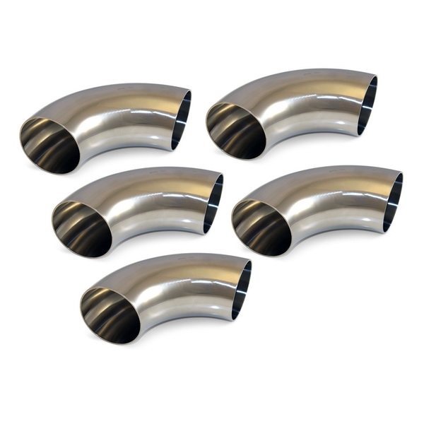 47, clause 2.3.1 and table. 2.4, - the optical cable must be resistant to various mechanical stresses, including static bends (table 1).
| Parameter | Impact |
| Static bending resistance | 20 cycles of bends at an angle of ± 90° with a radius of not more than 20 times the outer diameter at normal ambient temperature and at an ambient temperature of minus 10°C |
Table 1. Requirements for the stability of the OK against bending
the minimum bending radius is 240 mm. We conclude that the minimum bending radius of an optical cable depends on its outer diameter.
Bend radius The OK has an effect on the bend radius of the optical fiber since it is located directly inside the optical cable. If the minimum bending radius of the optical fiber is observed, the principle of optical signal transmission is not violated.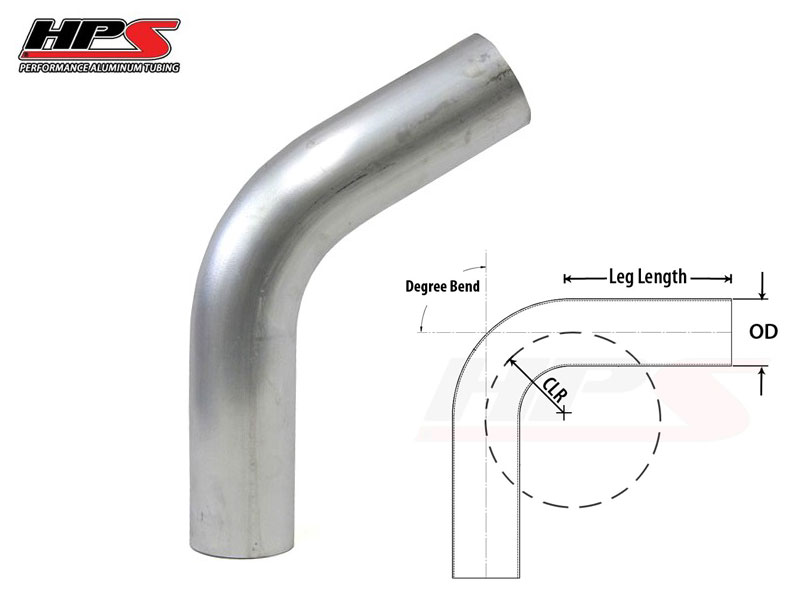 That is, the effect of total internal reflection is preserved and the signal is transmitted through optical fibers without unnecessary attenuation.
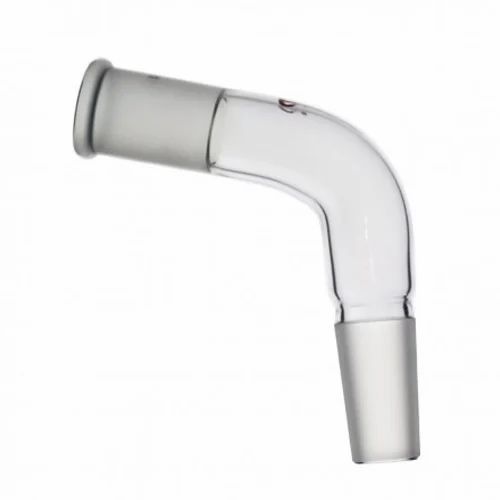
In the case when the minimum fiber bending radius is not respected, then a macrobend occurs at the bending point (Fig. 1), the light goes beyond the fiber core and attenuates. Excessive attenuation in the line is unacceptable, therefore, compliance with the minimum allowable cable bending radius is a prerequisite for the construction and operation of FOCL.
Figure 1 Macrobend
The minimum bending radius OK is always indicated in the specifications for a specific brand of optical cable. Depending on the fibers used in the optical cable, the radius may be less than specified in the rules (No. 47, dated April 19, 2006).
If the manufacturer defines a minimum bending radius less than in the rules, then this is confirmed by numerous tests.
During the construction and operation of fiber optic communication lines, the following general rules must be observed:
Let's consider two completely different constructions of OK:
Standard optical cable into the ground (DPS cable)
Figure 2. Standard into the ground (DPS cable)
: at least 15 cable diameters . The cable is laid mainly on flat areas in a trench or with the help of a cable layer.
Indoor distribution (OBR cable)
Figure 3. Distribution (OBR cable)
The operating parameters on OK indicate - minimum bending radius: at least 10 cable diameters . It is laid along various cable channels, cable growths. In this case, various bumps, sharp edges and transitions occur along the cable path. Therefore, it is important that the cable has the smallest possible minimum bend radius, without negatively affecting the optical fiber.
There is no division into minimum allowable radii during installation and operation in the industry requirements. Therefore, all used mounting rollers, reserve coils, etc. must have an inner radius not less than the minimum allowable for the cable.
Share:
For example, a paper-insulated cable with an aluminum sheath, armored with two steel tapes, with a protective cover, has an outer diameter of 60 mm. The permissible bending radius must be 60x25=1500 mm, i.e. R =1500 mm. If R is less than acceptable, corrugations will form on the aluminum shell, and the paper insulation will begin to tear.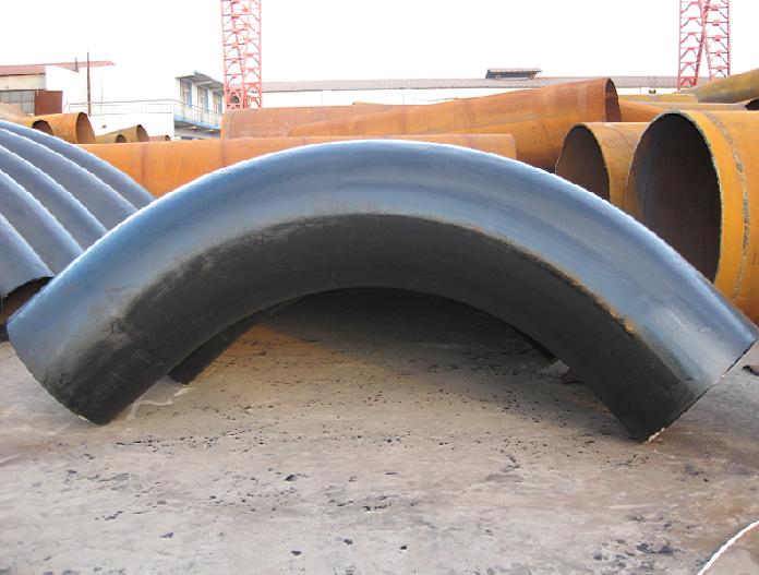
The multiplicity of the radius of the inner bending curve of the core in relation to the diameter of the core for cables with a voltage of 1-10 kV with paper and plastic insulation must be at least 10 core diameters.
If the conductors are sectorial, the diameter of the conductor is determined by the height of the sector.
When installing all types of terminations on cable lines with a voltage of 1-10 kV, the cores must be cut to such a length that it is possible to rearrange the cores of all phases during operation. Due to the increase in the lengths of the veins, they must have a bend. Sections with a bend must be located above the body of the termination:
for end fittings with bituminous mastic above the edge of the bushings by 100 mm; for end fittings from tapes 150 mm higher than the winding at the spine of the couplings.
the smallest radii of the bending curve of cables in relation to their outer diameters are given.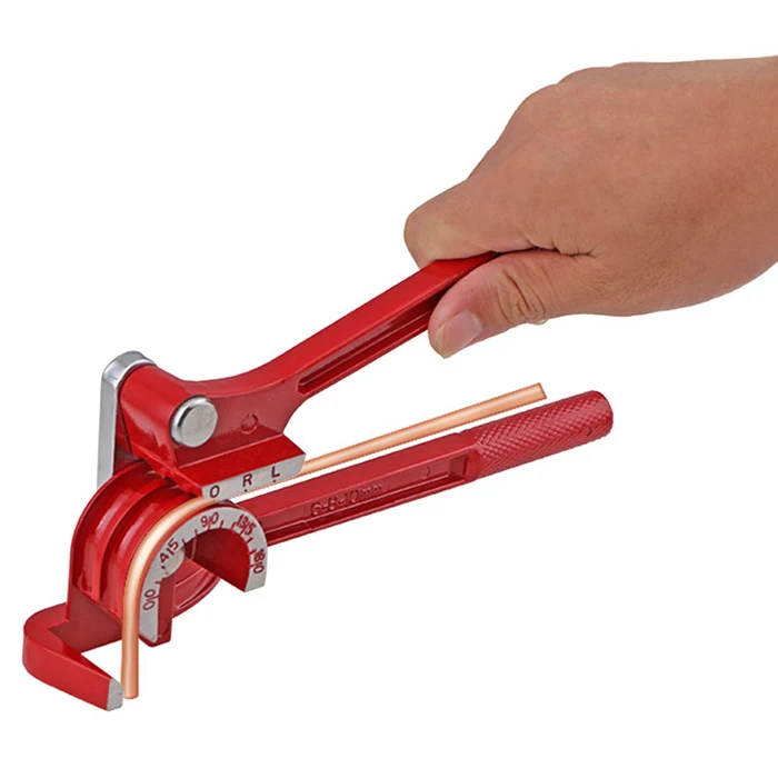

 gives shrinkage)