“A tire only loses air if it’s punctured.” This is a common misconception that we have all had or heard and yet the reality is quite different. Indeed, a tire can lose air even without a puncture, as for example in the case of a crack in the valve that is used to inflate your tires. A punctured valve is difficult to detect, and not taking care of it in time can have real consequences for your tire, but also (and above all!) for your safety. Blackcircles Canada, your online tire specialist, offers below a complete guide to the causes and consequences of a punctured valve, and how to repair a leaking valve stem.
A valve is a pin located on the outside of the tire, through which the tire can be inflated/deflated. It has a mechanism consisting of a spring-mounted valve that closes tightly with the air pressure inside the tire. Over time, the stem valve may become brittle and cracked, which may increase the risk of air leaking through it.
When the stem valve leaks, the affected tire is no longer able to retain air. Depending on the extent of the damage, the air will leak out slowly or more quickly. In both cases, the valve must be replaced.
If the air leakage is slow, you will be subject to the problems encountered by drivers driving with underinflated tires. Internal damage that can shorten the service life of the tire by up to a quarter, increased fuel consumption due to higher rolling resistance: the tire will damage faster, and your energy-efficiency will be significantly lower. The tire will also have poorer traction and the stability of your car will be reduced when cornering, not to mention the more pronounced deformation of the tire that increases its internal temperature, which can cause it to burst. Finally, an under-inflated tire increases the risk of hydroplaning. Tire pressure is thus very important!
 Here’s how to do it!Step 1: Make sure it’s your valve stem that’s leaking.
First of all, make sure it is the tire valve stem that is leaking. To do so, there’s a very simple trick! Apply a mixture of water and dishwashing soap to the valve with the cap removed. If bubbles start to appear, your valve is leaking. If this is not the case, and there is a definite air leak, it will be located elsewhere on the tire.
Step 2: Gather the right tools before you start!Before you begin, make sure you have all the necessary equipment to complete the replacement of the faulty valve stem.
For this, you will need the following:
You are now ready to start the process!
Step 3: Loosen the nuts on the wheel you are going to work on.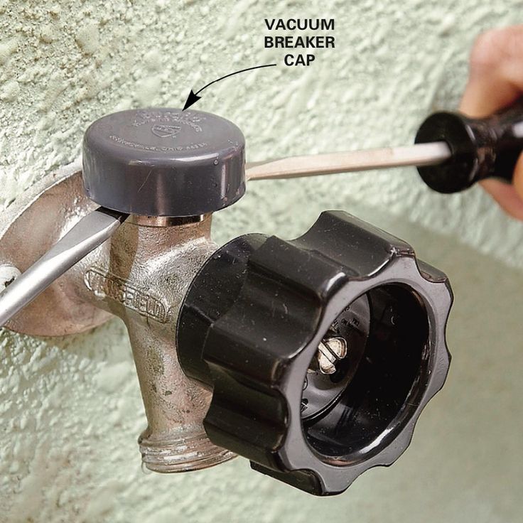
To do so, use the wrench mentioned in the previous step to loosen each of the lug nuts holding your wheel in place. Do this while the car is still on the ground.
However, for certain models of vehicles, it is possible that the wheel nuts have an anti-theft ring. If this is the case, you’ll have to use the appropriate special key to remove the locking nut(s).
Step 4: Raise your vehicle with the jack and then remove the wheel.First and foremost, make sure the handbrake is applied so that your vehicle is completely immobilized. Then, use your jack to lift your car. Be sure to position it on the right part of the chassis so that the car is properly supported. This will prevent any damage to the car and any bodily injury. Once your car is lifted, secure it on jack stands. Unscrew the wheel bolts completely, then remove the wheel. Finally, place the wheel on the ground flat, with the outside of the wheel facing up.
Step 5: Remove the valve stem core with the removal tool and let the tire deflate.
If you have not already done so, remove the valve cap. Then remove the valve stem core using the valve stem removal tool to release the air from the wheel, which should normally deflate completely on its own.
Step 6: Separate the tire’s bead from the wheel.For this step, use the sledgehammer in the following way: hit the tire sidewall with the sledgehammer in the same spot until you hear a crack or popping sound, and see the inside lip of the tire visibly break loose from the rim. This means that the tire has been successfully detached from the lip of the wheel.
Once the tire bead has been broken, continue hitting with the sledgehammer around the tire to detach the sidewall around the entire circumference of the wheel.
Step 7: Remove the tire from the rim.Once the sidewall of the tire is separated from the outer edge of the rim around the entire circumference of the wheel, insert your tire iron between the edge of the rim and the inside lip of the tire, and then pry upward to pull the lip of the tire over the edge of the wheel.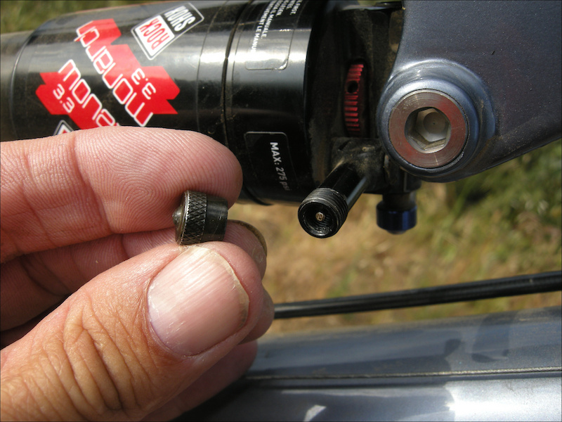 Once you have pulled the lip of the tire over the edge of the wheel, work the tire iron around the rim until the entire lip of the tire is off the rim.
Once the sidewall of the tire is completely above the wheel, grab it by its removed lip and pull it upward so that the opposite lip that was at the bottom of the wheel is now touching the top edge of the rim. Use your tire iron again by inserting it between the tire’s lip and the edge of the wheel and pry upwards to pull the lip over the edge of the rim. As before, work the tire iron around the edge of the wheel until the tire is removed from the wheel.
Step 8: Remove the defective valve stem and replace it with the new one.Once the tire is separated from the rim, it is time to remove the valve stem. To do this, first pull out the valve stem free from the wheel using the needle-nose pliers. Once this has been done, install the replacement valve stem from the inside of the wheel. Once it is in position, use the needle-nose pliers again to pull it through into its right place on the wheel.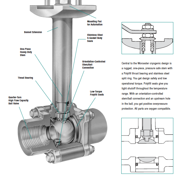
Once the stem is in place, it is time to put the tire back on its rim. To do this, start by pressing the tire down over the rim until the bottom bead clears the edge of the rim. The aim here is to return the lower sidewall of the tire to its original position on the wheel.
Then press the upper sidewall of the tire down underneath the edge of the wheel. Then tuck your tire iron between the tire sidewall and the rim edge and use it to make the opposite movement to the one you used to pull the tire sidewall out of the rim. Once the bead clears the lip of the wheel, use the tire iron to work your way round the entire wheel until the tire is completely installed on the wheel. Then inflate it to the correct pressure using the air compressor.
Step 10: Make sure there are no other leaks, and mount your wheel back on!Once the tire is inflated to the correct pressure, check for other leaks. If all is well, mount the wheel on your vehicle and bring it down by lowering the level of the jack stands until the repaired wheel touches the ground and you can safely remove them.
Ultimately, it is very important to make sure your tires are free of air leaks to maintain proper air pressure at all times. In the case of a slow air leak, the consequences can be dramatic. If the air leak is due to a faulty tire valve, you will definitely need to replace it. You can either follow the above procedure on how to repair a leaking tire valve or take it directly to a specialist. If, on the other hand, you need to change the entire tire, consult our selection of tires adapted for your car directly online on our website!
Tire Installation 101: When and how to change your tires?
A leaky tubeless value is one of the most annoying things that can happen to a cyclist. It can be a tricky fix to stop air leaking out, and diagnosing the problem can additionally be tedious. Of course, some say it’s easy and can simply be fixed with a quick bit of tape.
However, without knowing what to look for, it’s challenging to identify the root cause of the problem. That means you need to remove the tire and take a proper look at the issue. And, of course, that makes the whole operation a lot more complicated.
This post might contain affiliate links for which we may make a small commission at no extra cost to you should you make a purchase. Learn more.
Even if you’re experienced in fixing a leaking tubeless valve stem, it can still be a tricky fix. Here are the reasons why it happens and some top tips to fix it.
Why does it happen?A leaking tubeless valve stem is mainly caused by two issues – a damaged or incorrectly installed tape, or a value that is not set up properly.
If the tape around the tubeless value stem is in any way compromised, then air will leak into the rim, which in turn will usually be released through the valve stem hole. This air leakage can occur because the valve stem isn’t sealed tightly so it’s the logical option for the air to escape.
If you can hear the air pressurising out of the valve stem, the first step is to make sure the valve stem is set up correctly. If the valve stem is installed correctly and is tight, but the air is still leaking, the cause will be damaged or poorly installed tape.
How tubeless systems workBeing tubeless, there is no inner tube to hold the air inside your bike tire. Instead, the tire is sealed by an airtight fit between the rim and the tire, preventing air from leaking out.
For that to be successful, there needs to be a layer of rim tape that closes the rim spoke holes and helps seal the air in. Hence one of the main causes of air leakage being damaged tape. Because the rim spoke holes are quite large and sharp, the tape is normally pretty rugged and durable.
The tubeless valve is an additional part that is normally sealed with rubber close to the valve hole on the rim.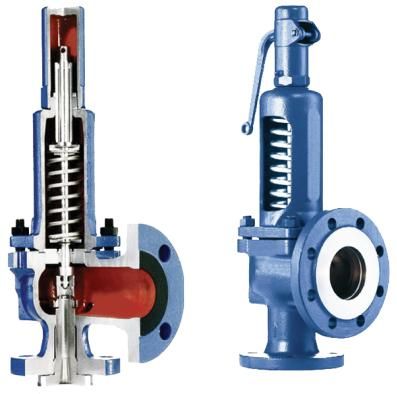 The valve stem is tightened by a locknut, which can be seen on the outer side of the rim.
Tires need to be ‘tubeless ready’, so normal bike tires can’t be used on a tubeless set up. This is because tubeless tyres have stronger side walls so they don’t leak air without an inner tube.
Tubeless tires hold the air much the same as an inner tube does, with the tire’s bead sticking to the rim and rim tape to seal the air in completely.
If there are any gaps, tubeless tyres typically have a sticky sealant poured inside the tire to plug the holes effectively. That helps if you get a puncture as the sealant works to close the damage.
Some riders use double layers of rim tape to create a stronger seal inside the tire, however, it can add extra weight to the wheels and is also harder to replace. To perform properly, tubeless rim tape must be sticky.
If the rim tape isn’t sticky enough or is made of poor quality, it’ll leave air bubbles and gaps between the tape and rim, causing air leakage. It also needs to mix well with the sealant inside the tire.
Additionally, tubeless rim strips are made specifically for certain rims, with a fitting for a tubeless valve. However, that can be a problem as they need to accommodate the valve and properly fit the rim they are on.
Because of the incompatibility with different rims and tubeless valves, tubeless rim strips aren’t particularly common anymore.
The tubeless valveAs mentioned, the tubeless valve is usually sealed by rubber. This is pretty effective at keeping air in, but can be damaged. For instance, if the whole valve twists, then the rubber block sealing it will get damaged and create a leakage gap. So they need to be treated carefully.
The other sealant options are a metal block with a rubber seal and a cone-shaped rubber seal. The metal block with rubber has issues with compatibility, so it’s often seen on modern bikes, but the cone-shaped rubber seal is a more popular option today.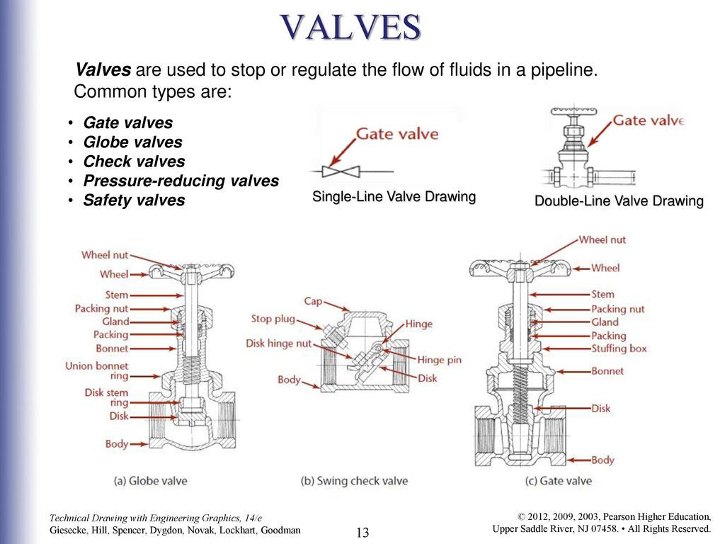
If the sealant is a cone-shaped valve, then the first thing to check is if the rim tape valve hole is completely opened. Make sure there is no extra room there by pushing in the valve and increase the tension with the locknut to try and seal all the gaps.
If the tubeless valve stem is still leaking, it’ll likely be a tape issue. It could be there are gaps in the tape installation, or there may be damage to the tape near the valve hole. If that’s the case, you can add tape to a small part of the damaged rim tape to form a patch and close any gaps.
If the problem is the valve stem itself, you can either change the valve stem or attempt to seal the gaps another way. That’d be a DIY option but you could use an old tube or rubber to create o-rings.
This isn’t advisable, however, as they are usually too thick and difficult to morph into the shape needed to plug the gap. Adding patches to the rim tape is another option, especially if the rim shape isn’t smooth.
The added thickness of the additional rim tape can help squeeze the gaps and seal the valve better. You could also add more sealant into the tire and spin the wheel once the valve is back on to try and create another inner layer of the goo.
Rim tape leakage caused by damaged tape is just as likely as leakage from the valve stem. If it’s because the rim tape isn’t sticky enough, then the only proper option is re-installing rim tape with a stronger and more robust option.
For cuts or splits in the tape, a patch of new tape will do the job. Split tape is unfortunately pretty common as the rim edges can be sharp.
Remember, never tighten a valve stem with pliers. It’ll damage the stem and cause further problems. If the valve stem is seated properly and tight, but the air is still leaking, you’ll have a breached tape.
If you’re trying to pump air into the tire, be careful not to force air through in case the tire blows off the rim. Additionally, if sealant is leaking out of the rim, particularly at the valve stem hole, you need to remove the tire and thoroughly re-visit the taping.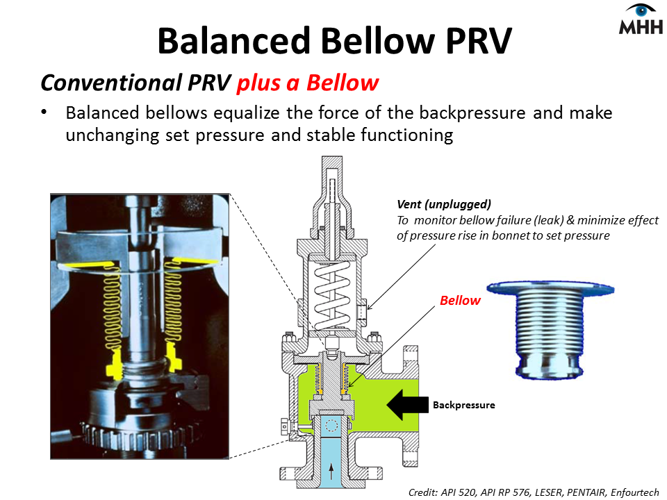
Check the tape, fix it if required, and ensure the valve stem isn’t faulty and is seated firmly in the rim hole.
Putting your air leakage problem behind youAir leakage in tubeless wheels, unfortunately, happen. The good news, however, the problem doesn’t need to be an end-of-the-world event.
In order to prevent the problem from happening, ensure the rim tape being used is a well-recommended, good quality option, and take care when installing it, and use proper tubeless tyre sealant to help seal the tyre and the rim. This should be replaced at least once a year.
Chris Smith
Founder of Vivi Nation, the cycling, running and active living brand. Chris is a sports enthusiast, occasional triathlete and experienced cyclist, having led multiple cycle tours across Europe.
As a general rule, valves are factory pressure tested to check for leaks before shipment. The type and method of testing conform to one or more of many different standards. The purpose of these tests and the expected results are often misunderstood and misused by the end user, resulting in unnecessary delays and unexpected costs.
There are many standards that define leak test requirements for faucets and valves. Often the difference between the two is unclear, leading to confusion about which one to use and why. First you need to understand that there are two types of leaks that are tested:
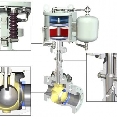 The allowable leakage rate depends on the valve test standard.
 Test methods for external and internal leakage are defined in numerous standards. There are too many to cover in one article, however, below we provide a brief explanation of some of the more common standards:
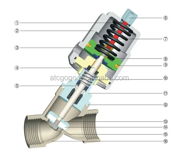
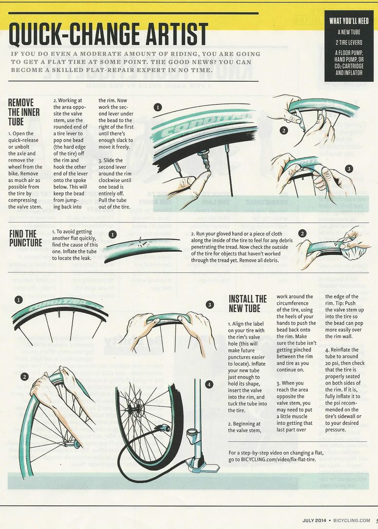 The standard has six different tightness levels from Class I to Class VI. It is important to note here that ANSI FCI 70-2 is for internal testing purposes only. It is not applicable for testing the external tightness of a valve and refers users to API-598 for valve testing.
 Typically, the first stop in the manufacturing process of an already assembled valve is an external test, known as a hydrostatic pressure body test. This test confirms the reliability and strength of the valve body. It also pre-pressures the valve body to help avoid rapid wear from cyclic pressure. For safety reasons, this test is usually carried out with water at one and a half times the pressure rating of the valve body.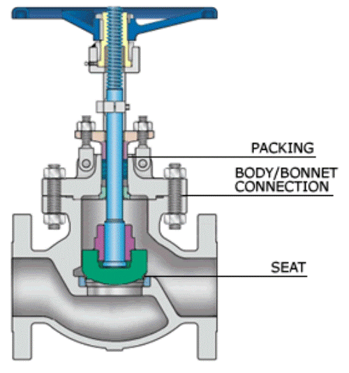 A similar test is also usually carried out on the fully assembled valve in the partially open position.
For body testing, API-598 refers to ASME B16.34 which lists body pressure ratings by material. For example, a Class 150 carbon steel valve (eg WCB) is tested at 31 bar. The same stainless steel valve (eg CF8M) is tested at 29 bar. The EN (European Committee for Standardization) and DIN (German Standards Institute) standards only take into account the pressure rating of the housing. So, regardless of the material of the body, the PN10 valve is tested at a pressure of 15 bar, and PN40 - at 60 bar. It is not uncommon for international business customers accustomed to working with EN and DIN standards to report that the wrong test pressure was applied when testing a valve body according to API or ASME.
Large ball valve on the test bench. A torque wrench at the end of the stem measures the torque required to turn the valve.In addition, even a simple test such as a body strength test has the following problems:
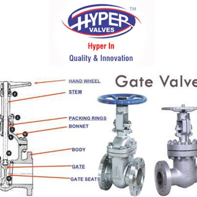 This occurs most commonly in monel and bronze castings. In order to detect a defect in this type of casting, the valve must first be tested with air, and then immersed in water or coated on the outside with soapy water. Such porosity can be blocked, in which case it will not be detected if the valve is first pressurized with water, as there is enough water to block the leak path. The valve standards do not mention this additional test, but it is advisable to use such tests with higher risk cast materials designed to handle dangerous and lethal gases.
 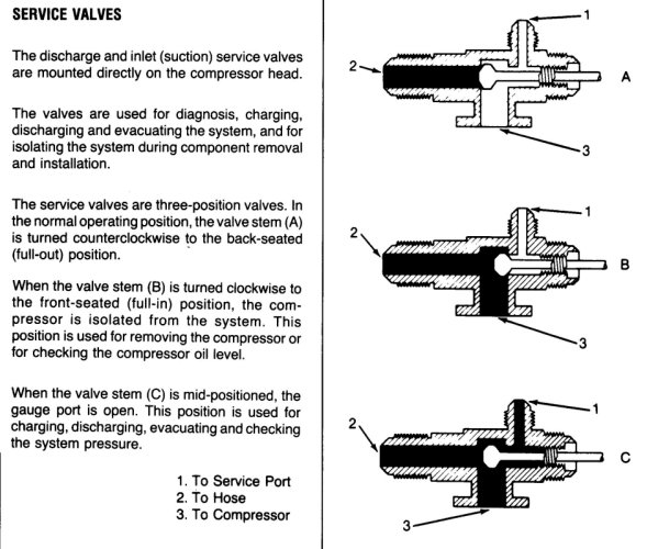 Water inside a fully assembled valve can lead to unwanted and unsafe contamination, and any residual water left after testing can be hazardous when put into service. For example, residual water remaining in valves for cryogenic service may freeze and interfere with valve operation. In such cases, it is best to check the body before assembling the valve.
  It is especially difficult to achieve a low stable level of chlorides if the plant uses a public or municipal water supply.
 Table 1. Blast Overpressure
| > 5 psi (0.34 bar) | Tympanic membrane rupture |
| > 15 psi (1 bar) | Irreversible lung injury |
| > 35 psi (2. | Deaths |
Although the arguments regarding external sealing or case testing seem strong, they are less complex than internal sealing. With regard to internal tightness, it must be understood that terms such as zero leakage and tightness are often misinterpreted, which is a very common blunder. The expressions "tight" and "zero leakage" are for further study. Table 2 defines the measurable leak rates and explains them in everyday terms.
Table 2.
| Leak rate | Reference leak rate | Description |
| 1 x 10 -8 | 1 cm 3 every 3 years | Diffusion of helium through glass per square centimeter of surface area. |
| 1 x 10 -7 | 3 cm 3 per year | Size of 3 balls or dice. |
| 1 x 10 -6 | 1 cm 3 every 2 years | Breathing into a leak of this size can provide enough moisture to temporarily close the leak for several hours. |
| 1 x 10 -5 | 1 cm 3 per day | A wetting agent or soap must be added to the test water to visually identify a leak of this size. |
| 1 x 10 -4 | 1 cm 3 every 3 hours | Rising bubbles in water can be visually identified. |
| 1 x 10 -3 | 4 cm 3 per hour | A leak of this size is easily detected in water by a short test. This is the sensitivity level of a typical factory air test. |
| 1 x 10 -2 | Too many! | Leaking sound is heard. |
Most internal valve tightness tests are performed with air for a relatively short period of time, from seconds to minutes. This time is sufficient to allow rapid visual observation of a significant leak without being excessively time consuming and without compromising the plant's ability to manufacture and ship valves.
Although rising bubbles in the water can already be observed at a leak rate of 1 x 10 -4 cm 3 per second, the factory test is short, so the sensitivity of a typical factory leak test is about 1 x 10 -3 cm 3 per second. This is roughly equivalent to four cubes (four game dice or marbles) of leakage per hour. As a rule, such a leak is insignificant, because it will take years for the gas to simply fill the volume of the pipe after the valve.
Increasing the duration from a few minutes to an hour causes the sensitivity of the test to reach the range of 1 x 10 -4 cm 3 per second. This is equivalent to one dice or ball in terms of leakage volume in three hours.
Often, an inexperienced technician will apply a soapy solution to the closure and wait an hour or more before observing the formation of foam. This test method provides a sensitivity level of 1 x 10 -5 , which is equivalent to one dice or leak ball in one day. Considering some of the dangerous gases the valve may contain, it is reasonable to expect that body connections and other static seals in the valve will be leak-tight when tested using this method. However, closures that are dynamic seals should not be expected to provide this level of tightness.
There are many different types of valves and trim designs with different materials. Hence, there are many testing standards that take into account the unique behavior of each of them.
Failure to read and understand the reasons behind the test methods leads to the second most common mistake, which is the belief that factory testing is done to confirm that the valve will operate at nominal pressure. The API and ISO standards carefully define the risk of this kind of thinking. Each contains an important note warning that high pressure testing of soft seated valves may degrade low pressure performance. The real purpose of a factory internal leak test is to test the quality of the final product, not the strength of the structure. The internal tightness test must be appropriate for the type of valve and must be the most difficult and comprehensive valve test. Resilient seated valves may have pressurized seals, in which case higher pressure may increase sealing forces, potentially masking any dimensional or surface defects. These types of valves are more difficult to pass the low pressure test and are the best indicator of build quality.
On/off valves comply with ASME, API and ISO standards. They may also be applicable to control valves that must provide isolation during operation. For example, butterfly valves are often used for both regulation and isolation. If the standard factory test is based on API or ISO, there is no need to perform an additional test according to ANSI FCI 70-2, as the quality of the assembly of the valve has already been verified.
A third common misconception is that factory production tests show how a valve will perform in service. Often, end users specify that the valve must be tested at process design pressure and temperature. While this is not a problem for a laboratory equipped to carry out such tests, it is impractical to do so in a typical factory environment.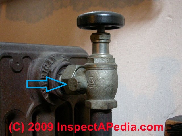 Such testing is a confirmation of valve design, not build quality.
Life would be easier if all valves were limited to no leaks for the duration of the test. But this is technically impossible. For valve pressure testing, it is advisable to use the manufacturer's standard practice. The manufacturer does not want to ship a defective product and is naturally motivated to use the most demanding test methods with the least risk of damaging the valve.
Ball valve test. Note the design on the top of the valve that is used to measure the leakage rate during the internal test. A stopwatch is used to measure the test time.
PKNE-50, PKVE-50 (PKEN-50, PKEV-50) electromagnetic safety shut-off valves
The valves automatically close when the controlled pressure goes beyond the set upper and lower limits, as well as in automatic control systems for gas-using devices when the voltage on the electromagnet is turned off. Valves are opened manually. Arbitrary opening of valves is excluded.
The operating conditions of the dampers must comply with the climatic version UHL 2 GOST 15150-69 with an ambient temperature of minus 35 to plus 45 0 C. The dampers may not be installed in hazardous areas.
Valves are manufactured with nominal diameters DN 50, 100 and 200 low PKNE or high PKVE controlled pressure.
PKN and PKV valves with electromagnets work only in one of the modes - pressure control or voltage control 220 V. At the same time, the valve does not work in both modes!
Technical characteristics
Under 15 years of operation, the product is subject to recycling
The device and the principle of operation
Corps 1 of the valve type 9000 2 . Cover 3 is attached to the adapter flange. A membrane 4 is clamped between the cover 3 and the adapter flange, the effective area of which for the PKV type valve is 8.5 times less than for the PKN type valve. In lid 3 , a large spring 5 is installed, the force of which is changed using the plug 6 , and a small spring 7 , the force of which is changed using the stem 8 . Inside the body 1 there is a valve 9. The sleeve of the valve 9 moves along the guide post 10 screwed into the body, and the valve stem 9 0 90 8
Valve lift 9 is carried out using a fork 12, fixed on the rotary shaft 13 , at the end of which is attached the lever 14 .
Valve 9 has a device that acts as a bypass valve to equalize the gas pressure before and after valve 9 when it is opened. When the valve is opened, the lever 14 engages with the anchor lever 15, mounted on the adapter flange 2 . The rocker 16 , installed in the lid 3 , is connected to the 4 membrane at one end, and the other with a hammer 17
to open a valve, you need to raise a lever 14,0009 to engage it with an anchor lever 15 . At the same time, the valve 9 rises and opens the passage for gas, which from the network through the impulse tube will enter under the membrane 4. The valve is adjusted to the lower response range by rotating the stem 8 , and on the upper range - by turning the plug 6 .
If the controlled gas pressure is within the specified limits, the rocker 16 , connected at one end to the diaphragm 4 , the other end will be aligned with the hammer stop 17 , which will be locked in a vertical position, raised manually.
If the controlled gas pressure rises above the set upper limit set by the large spring 5 , diaphragm 4 , overcoming the force of this spring, will go up and turn the rocker 16 , the outer end of which will disengage from the hammer stop 17 . Under the action of the load, the hammer 17 will fall and hit the free end of the anchor lever 15 , which will release the lever 14, fixed on the shaft, and the valve 9 under the action of its own weight and the weight of the load of the lever 14 will rest on the seat of the body of the lever 14 1 and shut off the gas passage. If the controlled gas pressure falls below the set limit set by the small spring 7 , diaphragm 4 under the action of this spring will go down and lower the inner end of the rocker 16 . This will disengage the outer end of rocker arm 16 from the hammer stop, which will fall and close the valve.
Electric actuator 18 is mounted on a bracket to the top of the cover 3. It is connected by a rod to the rocker arm 16 of the anchor-lever valve system.
The gas supplied to the valve passes through the inlet to the outlet, if to the actuator solenoid 18 Voltage applied. When the voltage supply to the electromagnet is interrupted, the rod 19 moves up, the tip of the rocker arm 16 will disengage from the hammer pin. As a result, the valve will be closed.
The valve is brought into the operating position after actuation by manually engaging the hammer pin with the rocker 16.
1 - body; 2 - adapter flange; 3 - cover; 4 - membrane; 5 - a large spring; 6- cork; 7 - small spring; 8 - stock; 9- valve; 10 - guide post;
12 - fork; 13 - rotary shaft; 14 - lever; 15 - anchor lever; 16- rocker; 17- hammer; 18 – electric drive; 19 - thrust.
Safety Instructions
Valves must be installed and operated in accordance with Gas Safety Regulations
Valves must be installed so that the direction of gas flow coincides with the direction of the arrow on the valve body.
The valve must not be installed in environments that are corrosive to aluminium, cast iron, steel, rubber and zinc coating.
All installation work must be carried out with process piping depressurized and power off.
The connection of the electromagnet to the mains supply must be in accordance with the general valve control scheme, "Electrical Installation Rules (PUE)".
The valve must be grounded, for which a Ø 20 mm pad is cleaned around the grounding bolt and the ground wire is connected with a bolt made of non-corrosive material. In places where the power wires pass through the screen of the electromagnet, install ebonite bushings.
In order to avoid accidents and accidents, it is forbidden:
- to start working with the valve without reading this instruction manual;
- Troubleshoot or repair a working valve;
- if you smell gas at the valve installation site, smoke, light matches, turn on and off the electric lighting (if it is not made in an explosion-proof version)
Installing and preparing the valve for operation
Before installing the product, it is necessary to depreserve the outer surfaces.
Installation of the device in places with a negative temperature is allowed provided that there is no condensation of water vapor in the passing gas at these temperatures.
The valve is mounted on a horizontal section of the pipeline in front of the pressure regulator. The membrane must be in a horizontal position.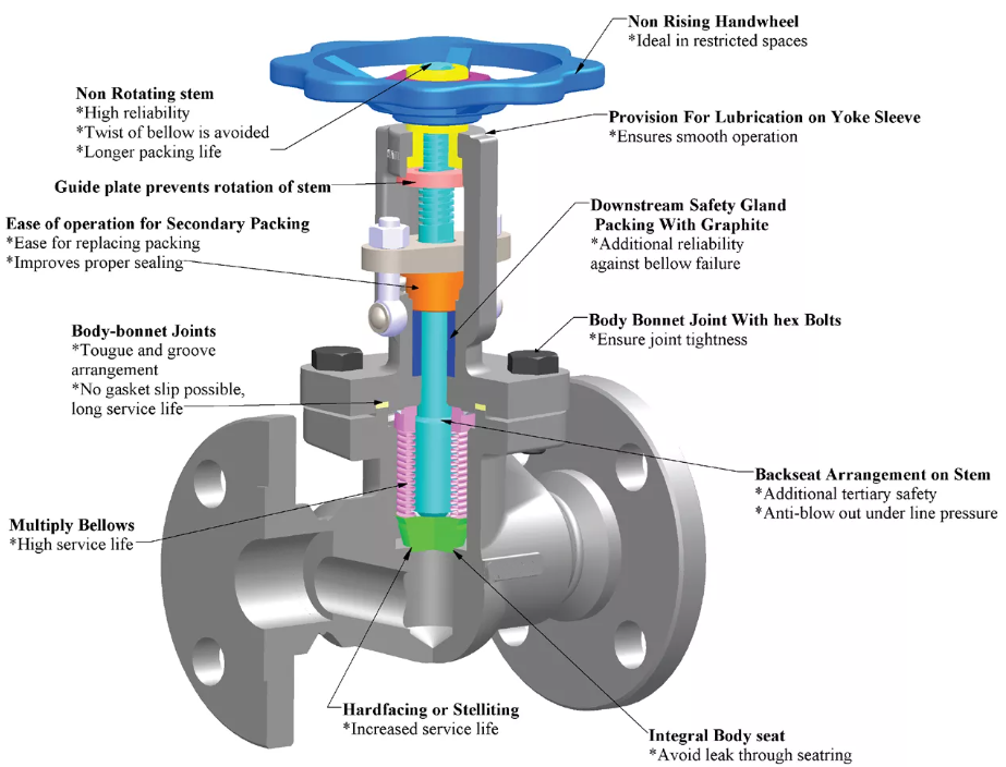 The gas inlet must correspond to the arrow cast on the body. The valve with its supporting surface is mounted on brackets or stands and does not require additional fastening. the direction of the slope, in which condensate can accumulate. Connection of a tube to the lower quarter of a horizontal pipeline in which pressure is controlled is not allowed. If, according to the installation conditions, such an arrangement is inconvenient, then it can be remounted. To do this, unscrew the nuts, remove the assembled head, swap the plugs and turn the fork axle over. Place the lever on the axle so that the axis of the lever bar coincides with the direction of the fork axis in the same plane, then fix the lever with a nut. Install the head by turning it 180 0 relative to the original position and screw on the nuts. After mounting and remounting the valve, check the reliability of knocking out the anchor with a hammer, the tightness of all connections with air, nitrogen or working gas at a pressure of 1.
 2 MPa. All sealing points of the sub-membrane cavity of the adapter flange shall be pressure tested for tightness: for PKN-0.1 MPa valves, for PKV-0.6 MPa valves. For the tightness of closing the valve with a pressure of 1.2 MPa and 0.002 MPa. Air leaks at the joints and seals are not allowed.
The valve must be sealed after adjustment by the user to the desired set pressure.
Operating procedure
After installation and pressure testing of the valve, it is necessary to adjust the operating parameters.
The following setting order is recommended.
First set the lower limit by turning the stem 8. During adjustment, keep the pressure in the impulse tube slightly above the set limit, then slowly reduce the pressure and check that the valve operates when the pressure drops to the set lower value.
Then set the upper limit by turning plug 6. During the adjustment, keep the pressure slightly above the set lower limit. After finishing the adjustment, increase the pressure and make sure that the valve operates when the upper limit is reached.
After finishing the adjustment, increase the pressure and make sure that the valve operates when the upper limit is reached.
When opening the valve after it has actuated, engage the hammer pin with the rocker arm only after eliminating the causes of the impermissible pressure change by pressing the diaphragm stem. In this case, the pressure in the head is recommended to be maintained slightly above the lower limit.
If the hammer does not move to the working vertical position at normal controlled pressure, the valve should be checked for proper operation.
Maintenance
During valve operation, preventive inspections should be carried out at least once every three months, and preventive maintenance - once every one and a half years.
During inspection, make sure that the valve operates within the previously established pressure limits, as well as that it rotates easily on the axes of the hammer and anchor lever.
The valve stem must move freely on the guide column.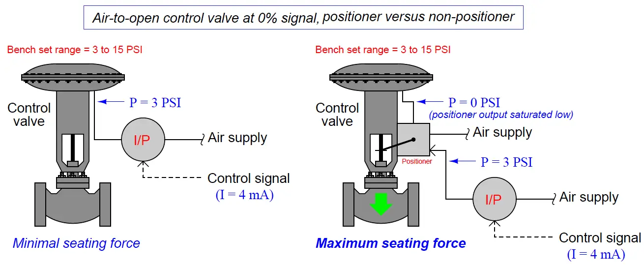 If necessary, clean the stem and guide column. To avoid dust settling, do not lubricate the guide.
The valve seat must be clean. Clogged seat causes valve leakage. Pay attention to the condition of the rubber seal. Over time, the rubber loses elasticity, which can cause leakage when the valve is closed.
Troubleshooting 9
Transportation and storage of valves
10.2. During long-term storage in a warehouse, valves must be re-preserved after one year of storage with conservation oil K-17 GOST 10877-76 or other lubricants for products of group II according to the protection option VZ-1 GOST 9.014-78
Shelf life no more than 6 years.
10.3. It is allowed to transport valves in universal containers without packaging with laying products in rows, separating each row with gaskets made of boards, plywood, etc.
Warranty period - 18 months 50, PKVE-50, PKVE-200, PKNE-200 with aluminum alloy body
Electromagnet for PKNE-50 valves, PKVE-50, PKEV-50, PKEN-50
000
Delivery of electromagnetic PKEN-50 valves (PKEV-50, PKVEV-50, PKVEV-50 50, PKNE-50) is carried out by transport companies in such cities as:
Abakan, Anadyr, Arkhangelsk, Astrakhan, Barnaul, Belgorod, Birobidzhan, Blagoveshchensk, Bryansk, Vladivostok, Vladikavkaz, Vladimir, Volgograd, Vologda, Voronezh, Gorno-Altaisk, Grozny, Dudinka, Yekaterinburg, Ivanovo, Izhevsk, Yoshkar-Ola, Irkutsk, Kazan, Kaliningrad, Kaluga, Kemerovo, Kirov, Kostroma, Krasnodar, Krasnoyarsk, Kudymkar, Kurgan, Kursk, Kyzyl, Lipetsk, Magadan, Maykop, Makhachkala, Moscow, Murmansk, Nazran, Nalchik, Naryan-Mar, Nizhny Novgorod, Novgorod, Novosibirsk, Omsk, Orel, Orenburg, Aginskoye, Palana, Tura, Ust-Ordynsky, Penza, Perm, Petrozavodsk, Petropavlovsk-Kamchatsky, Pskov, Rostov-on-Don , Ryazan, Salekhard, Samara, St.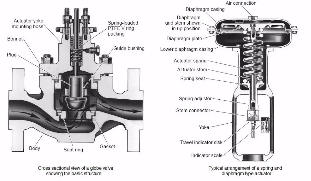 Petersburg, Saransk, Saratov, Sevastopol, Simferopol, Smolensk, Stavropol, Syktyvkar, Tambov, Tomsk, Tver, Tula, Tyumen, Ulan-Ude, Ulyanovsk, Ufa, Khabarovsk, Khanty-Mansiysk, Cheboksary , Chelyabinsk, Cherkessk, Chita, Elista, Yuzhno-Sakhalinsk, Yakutsk, Yalta, Yaroslavl, Astana, Abai, Akkol, Aksai, Aksu, Aktau, Aktobe, Alga, Almaty, Aral, Arkalyk, Arys, Atbasar, Atyrau, Ayagoz, Baikonyr , Balkhash, Bulaevo, Derzhavinsk, Ereymentau, Esik, Esil, Zhanaozen, Zhanatas, Zharkent, Zhezkazgan, Zhem, Zhetysay, Zhitikara, Zaisan, Zyryanovsk, Kazalinsk, Kandyagash, Kapshagai, Karaganda, Karazhal, Karatau, Karkaralinsk, Kaskelen, Kentau, Kokshetau , Kostanay, Kulsary, Kurchatov, Kyzylorda, Lenger, Lisakovsk, Makinsk, Mamlyutka, Pavlodar, Petropavlovsk, Priozersk, Ridder, Rudny, Saran, Sarkand, Saryagash, Satlaev, Semey, Sergeevka, Serebryansk, Stepnogorsk, Stepnyak, Taiynsha, Talgar, Taldykorgan , Taraz, Tekeli, Temir, Temirtau, Turkestan, Uralsk, Ust-Kamenogorsk, Usharal, Ushtobe, Fort Shevchenko, Khromtau, Shardara, Shalkar, Shar, Shakhtinsk, Shemonaikha, Shu, Shymkent, Shchuchinsk, Ekibastuz, Emba, Kerch, Evpatoria , Feodosia, Dzhankoy, Alushta, Bakhchisarai, Saki, Krasnoperekopsk, Armyansk, Sudak, Belogorsk, Inkerman, Shchelkino, Stary Krym, Alupka, Foros, Gaspra, Gurzuf, Massandra, Livadia, Simeiz, Koreiz, Marine, Kurortnoe, Novy Svet, Koktebel , Ordzhonikidze, Kiev, Minsk, Riga, Vilnius, Chisinau, Tallinn, Baku, Yerevan, Tbilisi, Bishkek, Dushanbe, Ashgabat, Tashkent.