Workshops
Projects
Blogs
Careers
Hire from us
For Business / Universities
Corporate Training
Academic Up-skilling
All Courses
Choose a category
Loading...
All Courses / undefined
All Courses / undefined / undefined
Loading...
Workshops
FOR BUSINESSES
Corporate Upskilling
FOR Universities
Academic Training
Hire from Us
Projects
We're Hiring!
AIM: To Analysis TATA ULTRA T.12 TRUCK by equating various calculation and observing the ratio of hill climbing power,gradeability, and to create Model the WOT (Wide Open Throttle) response of GM EV1 car. OBJECTIVE: To find the ratio of hill climbing power required by fully loaded tata ultra truck to the half loaded one.…
MATLAB
Project Details
Loading. ..
Leave a comment
Thanks for choosing to leave a comment. Please keep in mind that all the comments are moderated as per our comment policy, and your email will not be published for privacy reasons. Please leave a personal & meaningful conversation.
Please login to add a comment
Other comments...
No comments yet!
Be the first to add a comment
Read more Projects by kevin Ignatious Robert (43)
Week - 8 - Morphing
Objective:
AIM: To Perform Morphing for given models and Increase the height of the Dog houses and Ribs. THEORY: Morphing: Morphing is a special effect in motion pictures and animations that changes (or morphs) one image or shapes into another through a seamless transition.…
12 Apr 2021 07:04 PM IST
Read more
Week 6 - Creating connection for Rear door
Objective:
AIM: For the given Rear door FE model, Create and Apply different PIDs for different components and perform suitable connections. OBJECTIVE: To connect the different components in the rear door FE model with suitable connections. SOFTWARE USED: ANSA PROCEDURE:Importing the File: First, we want to import the given model…
20 Mar 2021 08:40 PM IST
Read more
Tool Test-2
Objective:
TIME TAKEN FOR THIS TOOL TEST: MODEL (INTAKE MANIFOLD) The time is taken for geometry clean-up is 15 minutes. The time taken to generate 2D shell mesh using trias in this model is 1 hour. The time is taken to clear the quality criteria of shell mesh is 45 minutes. The time taken for executing 3D tetra meshing or volume…
25 Feb 2021 06:05 PM IST
Read more
Week- 5 - Solid meshing
Objective:
AIM: For the given Rearview mirror component, check for the geometrical errors and mesh the Surfaces with the given 2D element Quality criteria and create a volume mesh with good surface quality (i. e. There should not and kinks and dips on the surface of the component.) OBJECTIVE: To check for the geometrical errors…
22 Feb 2021 03:50 PM IST
Read more
Tool Test 1
Objective:
TIME TAKEN FOR THIS TOOL TEST: MODEL-1(SWITCH PANEL) The time is taken for geometry clean-up is 45 minutes. The time taken for taking the mid surface of the switch panel model is 2 hours. The time is taken for geometry clean-up of the switch panel model is 15 minutes. The time taken for the meshing and quality criteria…
17 Feb 2021 01:31 PM IST
Read more
Week - 4 - 2D meshing for Plastic components
Objective:
AIM: To check for the geometrical errors for the given component. To extract all the mid surfaces of the given component with a suitable method. To mesh all components in the model with the given element Quality criteria. After meshing the component assigned thickness to the model. OBJECTIVE: To write a detailed report…
03 Feb 2021 04:54 PM IST
Read more
Project 2
Objective:
AIM: To check for the geometrical errors for the given component. To extract all the mid surfaces of the given component with a suitable method. To mesh all components in the model with the given element Quality criteria. OBJECTIVE: To write a detailed report on the meshing process and also mention which method we…
31 Jan 2021 07:54 AM IST
Read more
Week 12 - Project-1
Objective:
AIM: To check for the geometrical errors for the given component. To extract all the mid surfaces of the given component with a suitable method. To mesh all components in the model with the given element Quality criteria. OBJECTIVE: To write a detailed report on the meshing process and also mention which method we…
31 Jan 2021 07:48 AM IST
Read more
Week 9-Challenge
Objective:
OBJECTIVE: To Mesh the given Component with a Mesh size of 5mm. Create connector and Attach the various parts of the given model 1. Right_Rail_2 & Front_truss_1:- Seam-Quad(angled+capped+L) 2. Left_Rail_2 & Front_truss_1:- Quad elements 3. Front_truss_2, Front_truss_1 & Right_Rail_1:- Spot weld with 3 Layers and 5 mm…
09 Jan 2021 06:05 AM IST
Read more
Week 8-Challenge
Objective:
OBJECTIVE: To create 3D Meshing(Tetra mesh) for the housing model with Elements sizes: Min- 2mm, Target- 5mm, Max- 7mm, and Tet collapse: 0.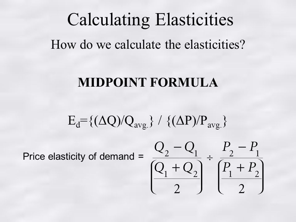 15 To create 3D tetra mesh for the two given models with 6mm element size. SOFTWARE USED: Hypermesh DEFINITION: TETRA MESHING: Tetrahedral is a four noded solid element that can be…
09 Jan 2021 06:03 AM IST
Read more
Meshing the Hood model using HYPERMESH
Objective:
AIM: To check for the geometrical errors for the given component. To extract all the mid surfaces of the given component with a suitable method. To mesh all components in the model with the given element Quality criteria. OBJECTIVE: To write a detailed report on the meshing process and also mention which method we…
21 Dec 2020 06:35 AM IST
Read more
Week 4- Challenge
Objective:
AIM: To create a mid surface for a given component and mesh that model. Also, create 1D elements for that component with a given cross-section and DOF. OBJECTIVE: a. To create Rod element:- with only translational DOF and RBE2 link Cross-Section: BOX- Dimension a= 12 mm …
09 Dec 2020 10:32 AM IST
Read more
FRONTAL CRASH OF NEON DODGE BIW USING RADIOSS
Objective:
AIM: To analyze, the frontal crash BIW of the car and observe the resultant output and energy plots from the simulation. OBJECTIVE: To check the unit system and either follow[Mg mm s] or [Kg mm ms]. To create an appropriate interface, friction 0.2 and recommended parameters. Make sure of no penetrations and intersections.…
02 Dec 2020 02:02 PM IST
Read more
SIDE CRASH OF NEON DODGE BIW USING RADIOSS
Objective:
AIM: To analyze, the Neon side crash -BIW of the car and observe the resultant output and energy plots from the simulation. OBJECTIVE: To check the unit system and either follow[Mg mm s] or [Kg mm ms]. To create an appropriate interface, friction 0.2 and recommended parameters. Make sure of no penetrations and intersections.…
02 Dec 2020 02:01 PM IST
Read more
ANALYSIS OF A CRUSH TUBE WITH DIFFERENT CONTACT INTERFACES AND NOTCH CREATIONS BY USING RADIOSS
Objective:
AIM: To create the mesh for bumper assembly and to study simulation of a crush tube in different cases. OBJECTIVE: To create the mesh for bumper assembly, mesh size should be 6mm. To run the crash tube model as it is. To change the Inacti=6 and run. To create the type 11 contact and run. To remove both notches and…
07 Nov 2020 10:01 AM IST
Read more
COMPARISON OF DIFFERENT MATERIAL LAWS WITH A SPHERE AND RUPTURE PLATE MODEL IN RADIOSS
Objective:
AIM: To run the simulation for seven different cases and to compare the results of seven cases. OBJECTIVE: To run the simulation by using the Failure Johnson model and named as Law2_epsmax_failure and save the results. To modify the Failure Johnson parameters of the previous model by changing the value of ifail_sh…
31 Oct 2020 06:23 AM IST
Read more
COMPARISON OF CRASH BEAM IN RIGID WALL BASE SIMULATION WITH IMPROVED ELEMENT SHELL PROPERTIES
Objective:
AIM: To compare the results with base simulation(study-1) and improved shell element properties(study-2) by using crash beam file as per given run time, animation steps, recommended properties of shell element, and finally to run the simulation of these two studies individually. Check the energy error and mass error…
27 Oct 2020 05:25 AM IST
Read more
Assignment 1
Objective:
AIM: To check the geometry cleanup, extract midsurface and to do 2D meshing for given three components they are practice model, clip repair, mounting bracket. OBJECTIVE: To write a detailed report on the 2D meshing process and also mention which method we used to extract the mid-surface. SOFTWARE USED: HYPERMESH (Radioss).…
17 Oct 2020 01:36 PM IST
Read more
Week 3
Objective:
AIM: To check for the geometrical errors for the given component. To extract all the mid surfaces of the given component with a suitable method. To mesh all components in the model with the given element Quality criteria. After meshing the component assigned thickness to the model. OBJECTIVE: To write a…
19 Sep 2020 08:13 AM IST
Read more
Project-1: Powertrain for aircraft in runways
Objective:
AIM: To list out the total weight of various types of aircrafts. To study the difference between ground speed and air speed. To explain how it is not recommended to use aircraft engine power to move it on the ground at the Airport. To study how an aircraft is pushed to the runway when it's ready to take off. …
08 Aug 2020 03:49 PM IST
Read more
CALCULATING THE EQUILIBRIUM POINTS AND STEADY POINT OF DRIVE USING MATLAB
Objective:
AIM: To study the Induction motor operation. To calculate the starting time of a drive with the given parameters. To explain the stability of a drive with the given parameters. OBJECTIVE: Study of induction motor operation and analysis of how the induction motor similar to the clutch. Calculating the starting time…
11 Jul 2020 02:22 PM IST
Read more
COMPARISON BETWEEN H-BRIDGE AND FOUR QUADRANT CHOPPER
Objective:
AIM: To study MATLAB demo ‘Speed control of a DC motor using BJT H-bridge’ and it with ‘The Four-Quadrant Chopper DC Drive (DC7) block’. OBJECTIVE: To run MATLAB demo ‘Speed control of a DC motor using BJT H-bridge’ and modify the model such that armature current doesn’t…
06 Jul 2020 06:01 PM IST
Read more
EV DRIVETRAIN
Objective:
OBJECTIVE: To explain the types of power converter circuits that are employed in an electric and hybrid electric vehicle. To solve the problem by data's that are given in the question and determine what is EV steady-state speed if the duty cycle is 70% To explain Induction Versus DC brushless motors by Wally Rippel,…
06 Jul 2020 06:01 PM IST
Read more
Week-6 Challenge: EV Drivetrain
Objective:
OBJECTIVE: To explain the types of power converter circuits that are employed in electric and hybrid electric vehicle. To solve the problem by data's that are given in the question and determine what is EV steady state speed if duty cycle is 70% To explain Induction Versus DC brushless motors by Wally Rippel, Tesla.…
27 Jun 2020 11:47 AM IST
Read more
COMPARISON OF HEV AND EV VEHICLE
Objective:
AIM: To comparing the HEV and EV vehicle by evaluating models and results of HEV and EV vehicle by using simulink. OBJECTIVE: To find the difference between mapped and dynamic model of engine, motor and generator. To change model type By two methods. To calculate miles per gallon and fuel flow for model…
16 Mar 2020 08:34 AM IST
Read more
ADVISOR TOOL
Objective:
OBJECTIVE: To Use ADVISOR tool and simulate following 1.For EV_defaults_in file, if cargo mass is 500 kg with all other default conditions, can the vehicle travel for 45 km with FTP drive cycle? Conclude your observations. 2.In above case, try changing the battery capacity and repeat the simulation. 3.Perform…
11 Mar 2020 08:42 AM IST
Read more
CALCULATIONS OF HILL CLIMBING FORCE ,GRADEABILITY , GRADE FORCE FROM DRIVE CYCLE AND WOT MODEL
Objective:
AIM: To Analysis TATA ULTRA T.12 TRUCK by equating various calculation and observing the ratio of hill climbing power,gradeability, and to create Model the WOT (Wide Open Throttle) response of GM EV1 car. OBJECTIVE: To find the ratio of hill climbing power required by fully loaded tata ultra truck to the half loaded one.…
09 Mar 2020 08:52 AM IST
Read more
Forces Acting on a Vehicle
Objective:
OBJECTIVE: To calculate the problem that are asked in challenge and finding the maximum speed of the motor used in an electric scooter capable to run at 90 kmph. To prepare a simple excel calculator to identify vehicle propulsion power based on given inputs and outputs. To find the difference in total traction power. To…
05 Mar 2020 09:26 AM IST
Read more
BAJA All-Terrain Vehicle (ATV) Model
Objective:
AIM: To Prepare a technical report explaining the model properties & comments on the results. OBJECTIVE: THEORY: MODEL 1: GENERIC ENGINE: ENGINE SENSOR: …
03 Mar 2020 08:41 AM IST
Read more
WASHING MACHINE AND GEAR SHIFT USING STATEFLOW IN SIMULINK
Objective:
AIM: Implement control logic of a washing machine using stateflow by giving certain condition as per power input and water input. As per this input ,machine operates and obtain output by lamp light. Create the stateflow for gear shift and vary the speed as input and obtain the ouput as the gear number in display. …
03 Mar 2020 04:22 AM IST
Read more
governing equation
Objective:
OBJECTIVE: The force on a cutting tool of a shaping machine varies over the length of cut as follows: Distance (mm) 0 20 40 60 80 100…
02 Mar 2020 05:25 AM IST
Read more
SOLENOID AND PLUNGER
Objective:
AIM: To Make a Simulink model of Doorbell using solenoid block. To use a thermistor to sense the temperature of a heater & turn on or turn off the fan OBJECTIVE: To Create a situation where the switch is closed for 2 seconds and then released. 2 From this equation we want to create a circuit diagram and find the output values…
26 Feb 2020 04:04 AM IST
Read more
FILE PARSING OF NASA THERMODYNAMIC DATA
Objective:
https://projects.skill-lync.com/projects/FILE-PARSING-OF-NASA-THERMODYNAMIC-DATA-61801
22 Feb 2020 08:08 AM IST
Read more
CALCULATING GLOBAL MAXIMA OF STALAGMITE FUNCTION BY USING GENTIC ALGORITHM IN MATLAB
Objective:
https://projects.skill-lync.com/projects/GENETIC-ALGORITHM-BY-USING-MATLAB-31233
20 Feb 2020 08:51 AM IST
Read more
CALCULATING GLOBAL MAXIMA OF STALAGMITE FUNCTION BY USING GENTIC ALGORITHM IN MATLAB
Objective:
AIM: To calculate the global maxima of a stalagmite function and to explain the syntax for Genetic Algorithm (GA) in MATLAB. OBJECTIVE: To write a code in MATLAB to optimise the stalagmite function and find the global maxima of the function. To expalin the concept…
20 Feb 2020 08:49 AM IST
Read more
CURVE FITTING FOR A LINEAR AND CUBIC POLYNOMIAL USING MATLAB
Objective:
OBJECTIVE: To Write code to fit a linear and cubic polynomial for the Cp data. And to Plot the linear and cubic fit curves along with the raw data points. To Explain the parameters used to measure the fitness characteristics for both the curves. THEORY: CURVE FITTING …
17 Feb 2020 04:05 AM IST
Read more
Simulation Of Transient Behaviour Of a Simple Pendulum using MATLAB
Objective:
https://projects. skill-lync.com/projects/SECOND-ORDER-DIFFERENTIAL-EQUATION-USING-MATLAB-73246
15 Feb 2020 04:32 AM IST
Read more
SECOND ORDER DIFFERENTIAL EQUATION USING MATLAB
Objective:
AIM: To simulate the transient behaviour of a simple pendulum using second order ODE's and to create an animation of it's motion using MATLAB. THEORY: SIMPLE PENDULUM Simple Pendulum's velocity and the displacement…
14 Feb 2020 01:58 AM IST
Read more
AIR STANDARD CYCLE SIMULATION USING MATLAB
Objective:
OBJECTIVE: To Simulate a P-V Diagram For Air Standard Cycle Or Otto Cycle and finding the thermal efficiency of the engine using MATLAB. THEORY: OTTO CYCLE: The Otto cycle consists of isentropic compression, heat addition at constant volume,…
13 Feb 2020 10:26 PM IST
Read more
FORWARD KINEMATICS OF A 2R ROBOTIC ARM MANIPULATOR
Objective:
AIM: To Simulate the forward Kinematics of a 2R Robotic Arm Manipulator. OBJECTIVE: To execute a program to simulate the forward Kinematics of a 2R Robotic Arm Manipulator & functions of workspace. THEORY: ROBOTIC ARM: …
12 Feb 2020 05:02 AM IST
Read more
CALCULATION OF DRAG FORCE USING MAT LAB
Objective:
CALCULATION OF DRAG FORCE USING MAT LAB AIM: To Calculate drag force for flow over bicycle. OBJECTIVE: To execute the program for plotting velocity vs dragforce with graph representation. To execute the program for plotting coefficient of…
11 Feb 2020 07:01 AM IST
Read more
Showing 1 of 43 projects
Try our top engineering courses, projects & workshops today!Book a FREE Demo
Anjali Mukeshkumar Sap, Naved Anwar Husain Farooqui2.
1,2Student, Department of Mechanical Engineering, Rizvi College of Engineering, Mumbai, Maharashtra, India.
Abstracts – This Design and analysis report of gearbox gives the theoretical and practical knowledge about the design, manufacturing and methodology of the gearbox for all terrain vehicles. This design of gearbox is as per the requirement of the BAJA SAE competition mentioned in the rule book of SAE BAJA INDIA 2020 [1]. Gearbox provides speed and torque conversions from the engine to the wheels. Gearbox is the main component in the transmission by which we can control the speed and provide the required amount of torque. This report gives an idea about how to set the perfect gear ratios as per the requirement of the BAJA SAE events.
Keywords – Transmission, ATV, SAE-BAJA, Gear box.
INTRODUCTION
The mechanism by which power is transmitted from an engine to the axle in a Vehicle is Transmission. Transmission is very important system to run vehicles. Transmission consists of Engine – CVT – Gearbox – axle Shaft – Wheels. CVT and Gearbox combinedly gives the power reduction ratios of engine to get the required amount of speed and torque. CVT means Continuous Variable Transmission, it gives the variable amount of reduction ratio in between 0.4 to 3.1 which reduces the engine speed. [4]. CVT has fixed ratios as it can't be changed in standard CVT eg. CVTech [4]. Therefore, Gearbox plays an important role in the transmission. The main objective of this study is to design and analyse the gear box for all-terrain vehicles.
BAJA competition is majorly of three parts: Static, Dynamic and Endurance races [1]. Static events is the presentation event [1]. In Dynamic events the effective speed and torque have to be produced by the Gearbox to tackle all the obstacles [1]. Endurance race is the 4 hour continuous race in which we have to run the vehicles on the track with the maximum speed [1].
METHODOLOGY
Considering all the events of Baja competition, gearbox has been designed in such a way that weight of the gearbox should be reduced, gears tooth does not go under failure. And hence to get the accurate gear ratio, to fulfil all the requirements, the Reverse engineering method is adopted to design the 2-stage gearbox. This method is very effective as we already know our requirements. First we calculate maximum load for our design by which our design will not go under failure.
The approach is in the following ways:
Calculation of Gear Ratios Design of Gears Calculation of Loads acting on the gears Gear Materials Selection Analysis of gears Calculation of factors depends upon the gears.
*Transmission Specifications:
Engine (as per the Rulebook of BAJA2020) [1]: Engine: 19L232-0054-G1 (Briggs and Stratton).
Power: 10HP = 7.46 kW
Engine Torque ( Te ): 19.67 Nm. Speed in rpm ( N ) : 3800 rpm.
CVT: CVTech [4]. Ratios: 0.4 to 3.1.
Wheels Diameter : 0.584 m / 23 inch.
Weight of vehicles: 220 kg.
Rolling Resistance (µ): 0.08
Rolling Resistance is the force resisting the motion when a body rolls on a surface. It depends upon the types of road and design of wheels. 0.08 is the maximum condition for all types of road, below the concrete it`s 1 i.e. worst case scenario.
Efficiency of transmission ( E ) : 75 % (Assumed by considering all the losses).
CALCULATION OF GEAR RATIOS
* Vehicles should not exceed the speed of 60 km/hr as per the SAE BAJA2020 rules [1]. By considering all the requirements, maximum speed up to 60 km/hr [1], acceleration and max. torque (considering 500 Nm max torque), we conclude that the Gear Ratio of two stage gearbox should be 9.11:1 by the following calculations.
Max.Speed of Vehicles = N * C * E* 3.6
C.R * G.R * 60
60 = 3800 * 3.14 * 0.584 * 0.75 * 3.6
0.6 * G.R * 60
Therefore, G.R = 8.72 .(1)
Torque on Wheels (T.W) = Te * C.R * G.R * E
500 = 19.67 * 3.1 * G.R * 0.75
Therefore, G.R = 10.933 .(2)
For the high speed low gear ratio is required and for the high torque we need higher gear ratio. Since the speed of the vehicles should not exceed 60 km/hr [1]. And to get the higher torque we concluded the gear ratio of 9.11:1 for the best performance.
Hence the first stage and second stages of gearbox should be
2.5 and 3.644 respectively.
Gear type is helical gear, which is having an inclined pitch by which chances of the failure of the tooth will be minimum.
| Gearbox Type | 2 stage compound gearbox |
| Gear Type | Helical Gear |
| Gear Ratio | 9. |
| 1st stage Reduction Ratio | 2.5 |
| 2nd stage Reduction Ratio | 3.644 |
| Pressure Angle ( ) | 20 degree |
| Helix Angle ( ) | 20 degree |
| Module | 2.5 |
Stage 1. Pinion-Gears Assembly
CALCULATION OF LOADS ACTING ON THE GEARS
IV. DESIGN OF GEARS
For the selected gear ratio 9.11:1 the Pitch circle diameter (PCD) and No. of teeth (Tn) is given by the following calculation.
Stage 1 gear ratio = No. of teeth of gear 1
No. of teeth of pinion 1
= 45 = 2.5
18
PCD for Gear 1
PCD = Tn * M = 45 * 2.5 = 120.75 mm
Cos Cos (20)
Same approach is done to get the rest values
| Stage 1 | Stage 2 | |||
| Pinion 1 | Gear 1 | Pinion 2 | Gear 2 | |
| No. | 18 | 45 | 17 | 62 |
| Face Width | 16 mm | 16 mm | 16 mm | 16 mm |
| PCD (mm) | 48.88 | 120.72 | 46.23 | 162.95 |
Stage-1 Pinion
Stage -1 Gear
For 1st stage gears:
Tangential Forces (Ft) = 2000 * Tn
P.C.D
= 2000 * 45
120.72
= 745.53 N
Axial forces ( Fx ) = Ft * tan
= 745.53* tan (20)
= 274.63 N
Radial Forces ( Fr ) = Ft * tan
Cos
= 745.53 * tan (20)
cos (20)
= 288.77 N
*Similar approach have to be done for the Second Stage Gears.
GEAR MATERIALS SELECTIONS
Gear materials selection is based on the amount of total load which acts on the gears or on gear tooth in the form of tensile strength or yield strength. The load which acts on the gears and gear tooth while dynamic and endurance races in the BAJA competition may cause the failure of the gears and breakage of gear tooth. The gear material should have sufficient strength to resist the failure due to breakage of the tooth.
Therefore this Materials has been selected:
| Gear`s Materials | Gearbox Casing Materials | |
| Material | EN353 | Al6061 |
| Tensile Strength | 680 MPa | 310 MPa |
| Yield Strength | 440 MPa | 276 MPa |
| Poisson's Rati | 0.26 | 0.33 |
ANALYSIS OF GEARS
Analysis has been done in ANSYS 16.0 on Workbench. Stress Analysis of 1st Stage Gears.
CALCULATION OF FACTORS DEPANDS UPON THE GEARS
Max. Speed of Vehicles = N * C*E*3.6
C.R*G.R*60
= 3800 * 3.14 * 0.584 * 0.75 *3.6
0.6 * 9.11 * 60
= 57.397 km/hr.
Acceleration:
>Tractive effort : It is the force act at the rims of the driving wheels of moving vehicles. It is required to accelerate the vehicle mass horizontally [7].
Tractive effort (T.E) =Te* C.R * G.R * E
R
= 19.67 * 3.1 * 9.11 * 0.75
0.292
= 1426.8 – 172.656
220
= 5.7 m/s2
>Gradeability: The ability of the vehicles to climb the slope is gradeability.
Gradeability = 100 * (T.E – R.R)
W
= 100 * ( 1426.8 – 0.08 )
220 * 9.81
= 58.11 %
Torque on Wheels (T.W) = T*C.R*G.R* E
= 19.67 * 3.1 * 9.11 * 0.75
= 416.625 Nm
Where, N: Speed of the engine (rpm) C: Circumference of Wheel (m) E: Transmission Efficiency (%)
C. R.: C.V.T Ratio G.R.: Gear Ratio
T: Max engine Torque (Nm) Te : Engine Torque (Nm)
R: Radius of Wheel (m) W: weight of Vehicles (N)
m: mass of the vehicles (kg) : Pressure angle
: Helix angle Tn: no. of Teeth
PCD : Pitch Circle Diameter (mm) M: module of gears
RESULT
| Gear Material | EN353 |
| Gear Casing Material | Al6061 |
| Gearbox Type | 2 Stage Compound Helical Gearbox. |
| Overall Gear Reduction Ratio | 9.11 |
| 1st Stage Reduction Ratio | 2.5 |
| 2nd Stage Reduction Ratio | 3.647 |
| Module (For all 4 Gears) | 2.5 |
| Pressure Angle | 20 Degree |
| Helix Angle | 20 Degree |
| Face Width (For all 4 Gears ) | 16 |
| No. of teeth in 1st stage ( Gear, Pinion ) | 45 , 18 |
| No. of teeth in 2st stage ( Gear, Pinion ) | 62 , 17 |
| Max. | 57.397 km/hr. |
| Acceleration | 5.7 m/s2 |
| Gradeability | 58.11 % |
| Torque on Wheels | 416.625 Nm |
| Gear Material | EN353 |
| Gear Casing Material | Al6061 |
| Gearbox Type | 2 Stage Compound Helical Gearbox. |
| Overall Gear Reduction Ratio | 9.11 |
| 1st Stage Reduction Ratio | 2.5 |
| 2nd Stage Reduction Ratio | 3.647 |
| Module (For all 4 Gears) | 2.5 |
| Pressure Angle | 20 Degree |
| Helix Angle | 20 Degree |
| Face Width (For all 4 Gears ) | 16 |
| No. | 45 , 18 |
| No. of teeth in 2st stage ( Gear, Pinion ) | 62 , 17 |
| Max. Speed of Vehicles | 57.397 km/hr. |
| Acceleration | 5.7 m/s2 |
| Gradeability | 58.11 % |
| Torque on Wheels | 416.625 Nm |
From all the Design, Analysis and calculation we concluded the following:
= 1426.8 N
>Rolling Resistance : It the force resisting the motion when a body rolls on a surface.
Rolling Resistance (R.R) = W * µ
= 220 * 9.81 *0.08
= 172.656 N
Total Resistance (T.R) = Air Resistance ( A.R ) + Rolling Resistance ( R.R )
>Air resistance: A force acting opposite to the moving vehicle by the air.
*Since the speed of the vehicle should be less than and equal to 60 km/hr. The air resistance will be negligible.
T.R = 0 + 172.656 = 172.656 N
Acceleration = T.E – T.R
m
CONCLUSION
The main aim of this study was to design and analyse the transmission gearbox for the SAE BAJA competition by using reverse engineering method. The overall gear ratios have been determined to get the required speed and torque.
Gear materials selection, number of teeth and gear type has been done to reduce the chances of failure. Analysis of the design has been done in the ANSYS 16.0 on workbench. And hence the gearbox is ready to transmit the required amount of speed and torque for the competition to tackle all the obstacles in the dynamic and endurance races in SAE BAJA competition.
REFERENCES
Rule book of SAE BAJA INDIA 2020
Gear Forces khkgears.net
A textbook for Machine Design by R.S. /khurmi and J.K. Gupta.
CVTech CVT catalog – http://www. cvtechibc.com/en/client/pagesoussectiondf3b.html?cl ef2=6
Boby George, Abin Jose, Adarsh John George, Ajay Augstine, Alvin Reji Thomas, Innovative Design and Development of Transmission system of an off-road vehicle, International Journal of Scientific & Engineering Research, Volume 7, Issue 3, March- 2016.
Dr. V.K. Sunil, Sunil Kumar, Abhishek Singh, Abhishek Srivastava, Amit Sharma, Prashant Dobriyal, Design And Development of a Transmission System for an all Terrain Vehicle Volume:04, issue:05 May-2017.
Tractive Effort
06/26/2018
PHOTO REPORT: AM-1 TULCHANKA COMBAT ATV FROM THE VICTORY PARADE IN ST. PETERSBURG. 05/09/2018
On May 9, 2018, a parade was held in St. Petersburg in honor of Victory Day. For the first time, AM-1 military all-terrain vehicles, manufactured by Russian Mechanics JSC in Rybinsk, were shown at the parade.
The AM-1 ATV was developed by Russian Mechanics on the basis of the civilian model RM 500-2 with a 4×4 wheel arrangement. Military all-terrain vehicles have a reinforced suspension, infrared protection, and mounts for grenade launchers and machine guns.
With a weight of 460 kg, the ATV can carry up to 500 kg using a towed trailer. 40 hp engine. With. allows you to reach speeds up to 80 km / h.
The power reserve of AM-1 is 300 km.
Engine start temperature range - from minus 20 to plus 50 degrees.
A 7.62-mm PKP Pecheneg machine gun or an automatic grenade launcher can be mounted on an army ATV.
Debuted in the AM-1 troops in 2015. This ATV has proved itself well in the Arctic, on sand dunes and dunes, as well as in mountainous conditions.
VTS "BASTION", 06/26/2018
AM-1 COMBAT ATV "TULCHANKA" FROM THE VICTORY PARADE IN ST. PETERSBURG. 05/09/2018
VICTORY PARADE OF 2018
07/06/2018
PHOTOREPORT: AM-1 TULCHANKA COMBAT ATV AT THE VICTORY PARADE GENERAL REHEARSAL IN MOSCOW. 05/06/2018
At the Victory Parade in Moscow on Red Square in 2018, the AM-1 Tulchanka combat quad bikes manufactured by Russian Mechanics JSC in Rybinsk were presented for the first time.
AM-1 all-terrain vehicles entered Red Square following the legendary T-34 tank, which led the motorized vehicle convoy. The standard of the front of the Great Patriotic War was reinforced on each "army man": 10 ATVs - 10 front standards.
The AM-1 all-terrain vehicle is designed for protection, reconnaissance, as well as search and rescue operations. It has been in service with the RF Armed Forces since 2015. Engine power 38 hp, full drive 4 × 4, high and low gears. Armament (optional): AK-74 assault rifle, SVD sniper rifle, grenade launcher. The AM-1 boasts a gas tank with a self-tightening coating, an engine preheater and a spotlight.
VTS "BASTION", 07/06/2018
AM-1 COMBAT ATV “TULCHANKA” AT THE VICTORY PARADE REHEARSAL IN MOSCOW. 05/06/2018
VICTORIES OF 2018
06/30/2020
About 10 units of modern motorized transport equipment (quad bikes) of high cross-country ability entered service with the reconnaissance training center of the Daryal training ground of the Southern Military District (SMD) in North Ossetia.
Scouts of the Southern Military District will actively use army ATVs, first of all, in solving reconnaissance and sentinel tasks, during raids and search and rescue operations.
Military personnel authorized to operate highly passable motorized transport vehicles completed a special training course and received permission to operate it in the field and in populated areas.
ATVs of the Daryal training ground for the first time took part in the Victory Parade on June 24 this year. and drove in the ranks of a mechanized column along the main square of the city of Vladikavkaz.
Press Service of the Southern Military District
04/05/2021
AM1 ARMY ATV FOR MILITARY POLICE AND VDV SHOWED AT THE ARMY-2019 FORUM
At the International Military-Technical Forum (IMTF) "Army-2019" in Kubinka, the Ministry of Defense of the Russian Federation presented several variants of the army all-terrain vehicle AM1 "Tulchanka", manufactured by JSC "Russian Mechanics" in Rybinsk.
Debuted in the AM-1 troops in 2015. This ATV has proved itself well in the Arctic, on sand dunes and dunes, as well as in mountainous conditions.
At the Victory Parade in Moscow on Red Square in 2018, the AM-1 Tulchanka combat ATVs were presented for the first time. In St. Petersburg, at the military parade on May 9, 2018, the AM-1 was also demonstrated.
Military police vehicle "AM-1 ATV" is designed for high-speed movement of military police units over rough terrain.
CHARACTERISTICS
Engine power, kW/hp: 38
Wheel arrangement: 4×4
Transmission, type: mechanical with CVT
Weight, kg: 375
Number of seats: 2
Maximum speed, km/h: 90
An armed army all-terrain vehicle AM1 was presented at the site of the Airborne Forces. It is designed for transporting personnel, cargo and towing trailers. The vehicle was armed with a Kalashnikov PK machine gun and two AK-74 assault rifles.
CHARACTERISTICS
Curb weight, kg 460
Payload, kg 300
Wheel formula 4×4
Capacity, pers. 2
Maximum speed, km/h 80
Power reserve, km 300
Engine:
- type Petrol
- power, hp 40
Ground clearance, mm 260
Gross weight
towed trailer, kg 500
Overcoming obstacles:
- rise (descent).
- without trailer 30°
- with trailer 20°
- slope 15e
VTS "BASTION", 04/05/2020
ARMY ATV AM1 FOR THE MILITARY POLICE AND VDV SHOWED AT THE FORUM "ARMY-2019"
ARMY ATV AM1 AT THE FORUM "ARMY-2019"
COMBAT ATV FOR amphibious groups AM-1 "TULCHANKA"
According to the documents, a combat ATV is called a mobile fire support vehicle. Purpose: to ensure the maneuverability of the fire support group, the flexibility of firing. Combat equipment: PKM machine guns, AGS-30 grenade launcher. Even anti-tank guided missile systems can be placed on an ATV. An additional platform is provided for placing reconnaissance instruments or transporting additional cargo. A significant amount of ammunition is attached to the ATV. Naturally, there is a satellite navigation system. A special Kevlar awning is also provided to protect against bullets and shrapnel. The patency of an ATV is no worse than that of a tractor. At the same time, it has good speed on a flat road and the highest maneuverability.
ATVs appeared at the request of the paratroopers themselves, who managed to convince the command that it is sometimes advisable to use light vehicles to quickly transfer a small group. The choice was made precisely on ATVs, which were developed at TsKIB (Central Design and Research Bureau of the city of Tula).
ATVs for landing groups "Tulchanka" were created on the basis of domestic equipment manufactured in Bryansk. "Tulchanka" has an AGS-30 grenade launcher and a PKM machine gun as its own weapons. These types of weapons allowed at one time Deputy Prime Minister Dmitry Rogozin to call ATVs "carts-tulchanki".
The AM-1 all-terrain vehicle was developed on the basis of the PM500-2 serial model with a four-stroke single-cylinder engine with a capacity of 38 hp. PM500 is the first all-terrain vehicle designed and manufactured in Russia. When designing it, the designers endowed the model with the best qualities of utility and touring ATVs. PM500 is truly Russian: simple, hardy, unpretentious and reliable.
PM500-2 - the new model, having borrowed the best from the PM500, has become even more comfortable. The car has become more maneuverable and easier to manage. High and low gears, all-wheel drive with the ability to lock the differential will cope with any off-road conditions.
The basic package includes front and rear cargo grills, electric winch, rear-view mirrors, passenger seat backrest, towbar, a complete set of lighting equipment. A comfortable two-level seat will comfortably accommodate the driver and passenger.
The AM-1 military all-terrain vehicle has a plug-in all-wheel drive, a special wheel mover with an increased tread, a load capacity of 300 kg and a speed of up to 80 km/h.
Can be operated in 20-degree frost. With its own weight of 500 kg, it is able to tow a trailer of the same weight. Equipped with a 2.5 ton electric winch with remote control.
Equipment for units of the Ministry of Defense also includes a mounting system for a grenade launcher and small arms - an AK-74 assault rifle and an SVD sniper rifle, a front trunk in which ammunition can be transported.
ATV's gas tank has a self-tightening coating, which eliminates fuel leakage if its integrity is damaged. Behind the passenger there is a place to accommodate two metal canisters of 20 liters each. For actions in the dark, in addition to ordinary lighting devices, the all-terrain vehicle is equipped with a searchlight headlight.
On November 14, 2014, joint exercises of Serbian paratroopers and Russian Airborne Troops will start in Serbia. Last week, six Russian military transport aircraft delivered to Belgrade not only the personnel who will take part in the maneuvers (servicemen of the 106th Airborne Division from Tula), but also military equipment. Questions were caused by the unloading of 15 ATVs.
Representatives of the command report that the Tulchanka ATVs will be used to perform a number of operations during which it is impractical to use heavy armored vehicles.
For the first time outside of Russia, their capabilities will be demonstrated by Russian paratroopers during exercises with Serbian colleagues.
The first batch of seven army all-terrain vehicles AM-1 in July 2015 entered service with the Arctic motorized rifle brigade of the Northern Fleet (SF). Transportation of ATVs was carried out in a semi-disassembled form. After receiving the new equipment, the specialists of the auto service of the connection assembled and tested it.
Army ATVs are entrusted to servicemen under a contract with significant experience in operating motorcycles and a driver's license of the appropriate category.
CHARACTERISTICS PM500-2
Basic parameters and dimensions
Capacity (number of seats), pers. 2
Unloaded (dry) weight, kg, not more than 400
Curb weight, kg, not more than 470
Maximum permissible vehicle weight, kg, not more than 630
Main overall dimensions of the ATV, mm:
length 2320
width 1245
height 1255
Base, mm 1490
Front / rear wheel track, mm 965 / 914
* Curb weight is the weight of the ATV filled with fuel and oil, with tools.
Engine
Model 507-3, petrol
Type four-stroke, single-cylinder, liquid cooling
Number of cylinders 1
Displacement, cm3 493
Maximum power, kW (hp) 28 (38) / 6000 min-1
Maximum torque N•m (min-1) 51 Nm / 5000 min-1
Compression ratio 10.9
Separate engine lubrication
engine oil API SH, SAE 15W-40/SF
Fuel motor gasoline
(with an octane rating of at least 92)
Carburetor T01Q000
Air filter Wet type element
Antifreeze coolant
CDI ignition system - electronic, non-contact
Electric starter, manual starter
Transmission
Stepless shifting method
Type of transmission mechanical
Automatic transmission (V-belt variator), with two-stage divider
Automatic clutch, centrifugal
Brake systems
working front: disc with manual hydraulic drive and additional foot
rear: single disc with foot drive
parking Mechanical (cable) drive to the brake mechanism of the rear wheels
Running gear
Front linkage suspension, with two hydraulic spring shock absorbers
Rear linkage suspension, with two hydraulic spring shock absorbers
Front tires 26x8-14 6PR
rear 26x10-14 6PR
Crankcase
Fuel tank l02 , l 2. 2
2
Front differential, cm3 300
Rear gear, cm3 150
Engine cooling system, l 3.5
Sources: www.rg.ru, Military Review, Rossiyskaya Gazeta, Press Service of the Northern Fleet (Severomorsk), rusatv.com and others.
ARMY ATV AM1 FOR THE MILITARY POLICE AND VDV SHOWED AT THE FORUM "ARMY-2019"
ARMY ATV AM1 AT THE FORUM "ARMY-2019" 05/06/2018
AM-1 COMBAT ATV “TULCHANKA” FROM THE VICTORY PARADE IN ST. PETERSBURG. 09.05.2018
Special vehicles
Special automotive equipment
Special, armored automobile equipment and tractors
Autobonian equipment
ATV driving equipment can become the theme of a full -fledged book. In the same article, we want to reveal to you the basics of safe riding. At first glance, there is nothing complicated in driving ATVs - you just need to steer and enjoy riding.
When driving over bumps, for example, those of the "wave" type, the driver must constantly change his position. So, when approaching an obstacle, you must shift your body back, otherwise you can hit the obstacle with your wheels. When driving over a bump, you need to move the body back forward, thus preventing excessive separation of the front wheels, i.e. rearing up the ATV. Then, when the rear wheels come off the ground, you need to move back again, otherwise you can fall out of the saddle, hitting your knees on the steering wheel.

Moving in a straight line at low speeds (up to 40 km/h), you can afford to relax. But at higher speeds or when passing sharp turns and slopes, the driver must move very actively. Indeed, due to the high center of gravity, short wheelbase and small width, ATVs are very prone to rollovers. In addition, if the motorcycle flies separately from the motorcyclist during falls, then the ATV most often covers the driver. Therefore, in order for ATV riding not to end with serious injuries, it is necessary to study the driving rules and strictly follow them.
ATV rider's weight is an important factor that affects machine handling. By shifting their weight, the driver can unload or load the front or rear of the ATV, thus compensating for centrifugal forces.
The first rule you need to learn is that when riding an ATV, you need to relax your arms. When driving, the driver can always let go of his hands, because his legs are holding him in the saddle. As the speed increases, the load on the legs also increases.
Conventionally, three racks are distinguished. The middle stance is used when driving in a straight line without turning. When opening the gas, the body must be moved forward to unload the hands. Thus, the front strut is obtained. When braking and closing the gas, the body, on the contrary, must be moved back, i.e. take a back seat. By the way, the word "stand" comes from the word "stand", and this name is not accidental. When actively riding an ATV, you do not have to sit. Standing on an ATV lowers your center of gravity. After all, there is a huge difference between the weight on a high saddle and the weight on the footrests. And the effect of moving the body in a standing position is much greater than from fidgeting back and forth on the saddle.
When going through a turn on a motorcycle, it is tilted inward, thus struggling with centrifugal force. But you can't do that with a quad bike. Therefore, it is necessary to use the weight of the driver. The main rule here is to always transfer the weight inside the turn. Moreover, it is necessary not only to tilt your shoulders. It is necessary to hang the entire body, including the fifth point. Only the shin and knee hold on to the saddle. Of course, if you turn at minimum speed, then you can limit yourself to turning the steering wheel.
The correct stance is characterized by slightly bent knees, elbows set apart, and a slightly arched and relaxed back. Why not stand on straight legs or keep your back straight and tense? Because bent knees allow you to absorb shock coming from uneven terrain. By the way, the force of these blows is sometimes quite enough to knock the driver out of the saddle. A straight tense back under such conditions can lead to injury to the intervertebral discs and even a compression fracture of the spine. Yes, and the internal organs with the wrong fit will have a hard time.
Active ATV riding requires good physical shape. So, in quad schools, the duration of the lesson does not exceed an hour, and at the end of the lesson, students can literally be squeezed out. And riding an ATV off-road is also an activity worthy of training in the gym.
When riding non-sport ATVs, it is best to avoid jumping. Firstly, this way you can break the ATV. Secondly, in order to safely perform such tricks, the ATV motor must have high-torque and fast response to the throttle. If, nevertheless, the jump could not be avoided, then it is necessary to land in the middle stance, but be ready to move to the back. When the wheels touch the ground, you need to slightly open the gas. It is better not to use four-wheel drive when jumping.
Every time you ride an ATV, you need to practice looking into the distance. This is necessary to develop the habit of evaluating the trajectory of movement in advance. Beginners often do not have time to track the road, and at some point they are not ready to perform adequate actions. And another, very predictable obstacle, can become a problem for them.
| When moving along a slope, it is necessary to move the body in the direction opposite to the slope. On the steepest sections, full overhang should be used, such as when cornering at speed.
|
Before you start climbing, you need to pick up speed. Then the resulting inertia will allow you to smoothly drive into the steepness.

 11
11 of teeth
 Speed of Vehicles
 of teeth in 1st stage ( Gear, Pinion )