SAFETY FIRST: Protective gloves and eyewear are recommended at this point.
Note: These instructions are very general, and you should have a service manual for your particular vehicle to get a better understanding of your particular setup and have factory recommended torque levels and specifications on hand.
Check out the Additional Service Information Resources for more information on finding service information for your specific vehicle.
If you are replacing axle carrier bearings see the ATV Axle Carrier Bearings guide.
Thoroughly clean the vehicle to make the job easier and prevent contamination of the new components during installation.
Get your steering bearing kit from ALL BALLS RACING.
Remove the contents of your ALL BALLS RACING rear axle bearing rebuild kit. Layout the components in an organized manner for easy installation.
Place the new bearings in the freezer for about an hour before installing them.
Remove the axle housings and axle from the final drive unit.
Remove the dust seals with a seal pick or flat blade screwdriver.
Remove the bearing from the axle housing with a suitable bearing puller or drive it out from the opposite side.
Clean away all of the old grease, grime, and rust from the bearing bore.
Inspect the bearing bore for wear and damage. Make sure the bore is free of damage or burrs that may cause the new bearings to hang during installation.
Install the new bearing into the axle housing.
Drive the bearing in until it is fully seated or to the OEM specified depth. Use a suitable driver or socket that only applies force to the outer race of the bearing.
Apply grease to the lips of the dust seal.
Install the dust seal into the axle housing.
Push the dust seal in so that it fits flush or as otherwise specified by the OEM.
Remove the hub nut, brake drum cover, brake drum, and shoes. Remove the brake drum panel from the axle housing.
Remove the dust seal with a seal pick or flat blade screwdriver.
Remove the snap ring with snap ring pliers.
Heat the brake panel around the area of the bearings with a heat gun.
Drive the bearings out.
Clean away all of the old grease, grime, and rust from the bearing bore.
Inspect the bearing bore for wear and damage. Make sure the bore is free of damage or burrs that may cause the new bearings to hang during installation.
Take the bearing out of the freezer and install it into the brake panel.
Drive the bearing in so that it is fully seated. Use a suitable driver or socket that only applies force to the outer race of the bearing.
Install the second bearing in the same manner as the first.
Use snap ring pliers to install the snap ring into its groove to secure the bearings.
Apply grease to the lips of the dust seal.
Install the dust seal over the bearings so that it fits flush or to the OEM specified depth.
Remove the old dust seal from the brake drum cover.
Clean up the seal area.
Inspect the seal area for damage.
Apply grease to the lips of the new dust seal.
Install the new dust seal into the brake drum cover.
Drive the seal into place with an appropriate driver that matches the outside diameter of the seal.
Assemble the vehicle. Replace any other seals with new items as necessary or as indicated by the OEM.
Tighten the fasteners to specification and Install new cotter pints with the hub nuts.
INSTALL ALL BALLS RACING STICKER!
The wheel hub bearings on your ATV or UTV will no doubt need to be changed out at some point. It’s not that hard of a job to do yourself with basic hand tools you probably already have. They do make specialty tools to make the job easier, but I’ve done this with ordinary tools everyone already has in their garage.
The steps I’m going to go over are universal steps for all pre 2010 ATV and UTV wheel hub bearing replacements. For ATVs or UTVs made after 2010 the steps will be similar and you may to also read the alternate wheel bearing replacement section at the bottom of this article.
There may be slight differences from machine to machine. But you’ll get the idea of what to do, and should be able to handle any slight differences your quad has. Having your service manual handy will help. And with all maintenance projects, it’s best to wear eye protection and gloves.
Here are the steps to replace your wheel hub bearings (I explain each step in more detail below)
Before I go into more detail about each of these steps, lets make sure you really do need to replace your wheel hub bearings. It’s not an extremely difficult job, but can take a bit of time and requires you remove a lot of parts from your quad. So lets make sure it’s necessary.
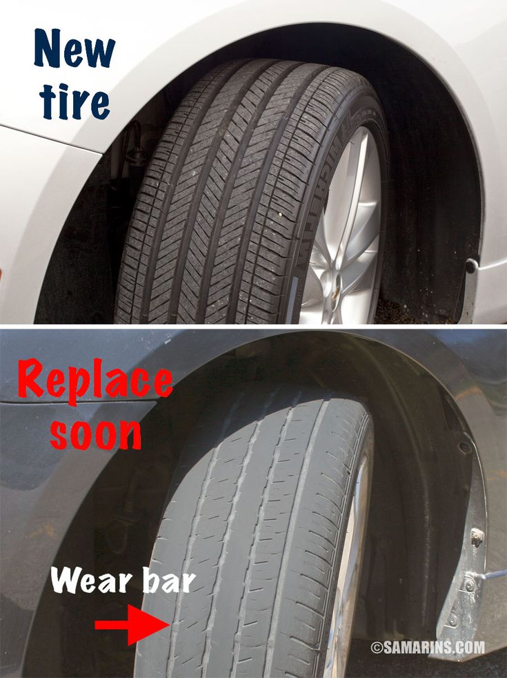
You’ll be able to tell if your wheel hub bearings are bad by the way your ATV or UTV is handling. One of the most common symptoms is a grinding sound and feeling when riding. You may also hear some clanking or banging type sounds coming from the wheel hub.
If they get bad enough, you could even feel vibrations and wobbling when riding. A wobbling feeling could also mean other things like you need to Balance Your ATV Or UTV Tires. If you notice the machine pulls left or right when braking, that could be a sign of bad wheel hub bearings as well.
If it’s been a while since you’ve last replaced them, or you have an older machine, it’s a good idea to do the replacement if your sure the problem isn’t your brakes or tires.
To do a manual check, jack up the wheel in question and try to move it back and forth.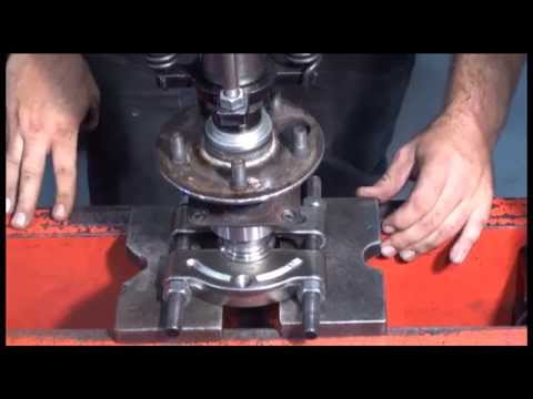 If the wheel is bolted on tightly but still wobbles back and forth, you probably need to replace the wheel hub bearings.
Most bearings come sealed, but over time, water and dirt will still find its way in there. There are ways to make the bearings last longer, which I’ll talk about later on. But eventually, they need to be replaced. Now on to the steps.
This goes without saying I suppose, but the ATV needs to be jacked up and remain so during this entire process. It’s a good idea to put in on jack stands as this can take a while and you don’t want your jack to fail.
Another safety measure you can take, after you take the tire off, put it under the quad near the jack stand. This is good to do just in case the machine falls off the jack or jack stands somehow. If you have a leg under there, it could save you a lot of pain.
I always start by loosening the lugs before I jack it up. That way it’s easier to remove when the ATV is lifted.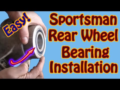 You don’t have to worry about rocking the machine while its raised up if you get a stubborn lug nut.
The caliper will typically be bolted on with two bolts, either an allen head bolt or a 12mm bolt.
Remove both bolts and the caliper should come off easily.
This may be a good time to Change The Brake Pads On Your ATV if they need to be done.
The caliper may have a line going into it, that’s ok you don’t need to remove that or do anything else with the caliper. Just move it and let it sit somewhere out of the way the best you can.
Remove Axle NutAfter you’ve got the caliper off, it’s time to remove the castle nut holding the hub in place. Usually there will be a cotter pin holding the castle nut in place.
This is to prevent the nut from loosening while you ride. The cotter pin is easy to remove with a pair of pliers. Some machines will have a stake nut here instead of a castle nut.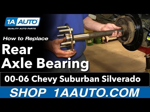
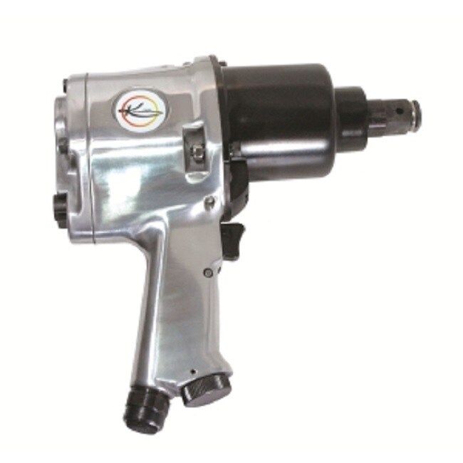
I found it easiest to remove the castle nut with an impact wrench. Sometimes they can stuck on there pretty good, and if you don’t have a breaker bar, doing it by hand can be tough.
Once the castle nut is off, you can remove the hub, which will usually have the brake rotor attached to it. Some machines will have a guard mounted on the knuckle behind the brake rotor. Remove the guard, this is easy to remove and is usually only held in place by a few bolts.
The upper and lower ball joints will be held on to the knuckle by nuts usually with cotter pins in them.
Remove the cotter pins and take the nuts off, you should be able to slip the ball joint out of the knuckle after that.
They sometimes take a little persuading, but usually come out pretty easily with a little hit from a hammer.
Do this for both the top and bottom ball joint connections to the knuckle.
Remove Tie Rod Ends From KnuckleTo remove the tie rid ends, you will typically need two wrenches. Most of the time they are about one size apart, that’s helpful if you only have one of each size wrench.
The bolts for the tie rod ends will most likely be held in with cotter pins too. Remove the cotter pins and bolts holding the tie rod end into place.
Once the bolts are off the tie rod end should easily lift up. Just pull it up out of the knuckle and move it out of the way. There is no need to take the tie rod end apart any further than this, you can just rotate it out of your way.
Remove Shock Absorber BoltYou only need to remove the bottom shock absorber nut and bolt. You will need two wrenches for this part as well.
The shock absorber is held in by a bolt and nut set up connecting to the swing arm.
I found it easier to hold the bolt in place with a wrench and use an impact wrench to remove the nut.
Once the bolt and nut are removed, you should be able to move the shock absorber up and out of your way.
On some models of ATV or UTV, it will help make this whole job easier to do this step right after you’ve removed the wheel.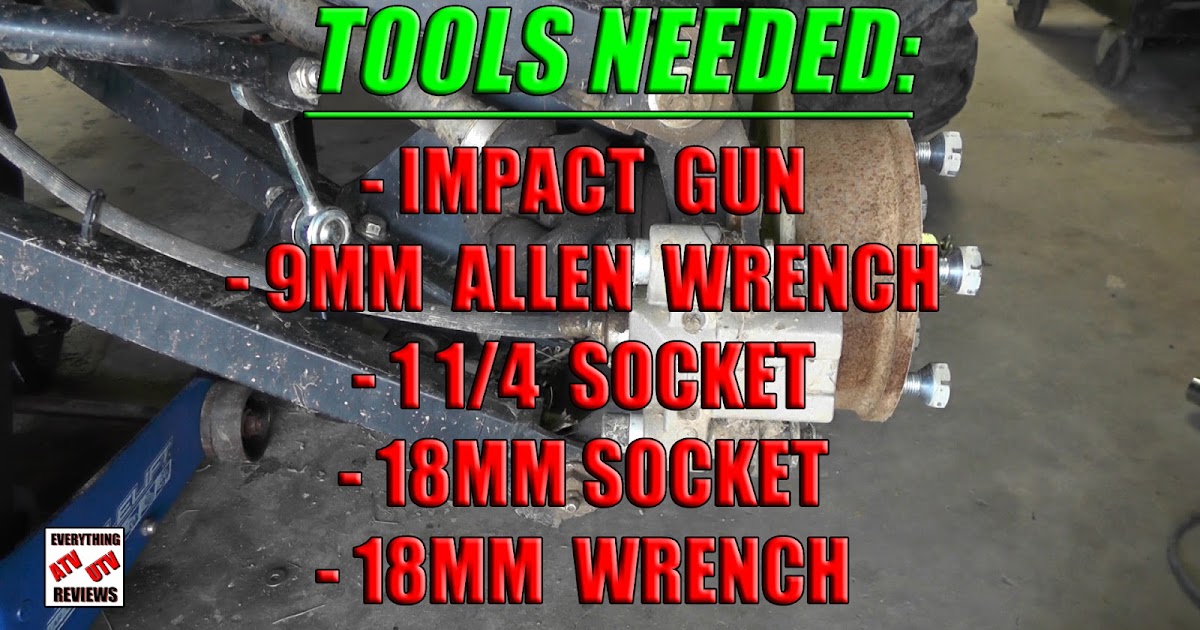 You will notice a better range of motion in the whole shock and swing arm assembly after you remove the shock absorber.
It can give you easier access to the other parts you need to remove in the previous steps. I’ve just always done it this way and never had any issues, it depends on your machine and how you want to go about it.
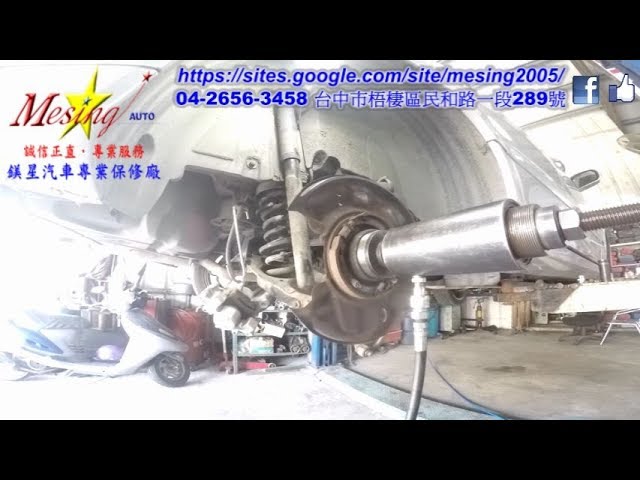
Remove Knuckle From SuspensionAfter you’ve removed the shock absorber bolts and got it out of the way, you should be able to just pull the steering knuckle assembly off the axle. Sometimes it can be a bit stubborn and you’ll have wiggle it to get it started.
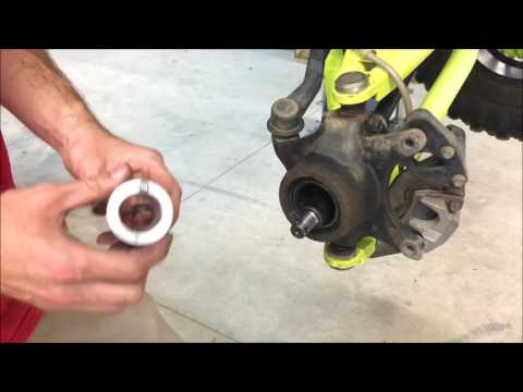
Remove Outer Seal And BearingsNow you’ll need to remove the seal and bearings from the steering knuckle. The seal will need to come out first.
They do make a special tool to make this easier like this Jecr Bearing and Seal Puller Tool from Amazon.
But I’ve got it done with just a screw driver before. Don’t get me wrong the seal puller tool makes the job a whole lot easier, and is useful for other projects as well. But you can get the seal out with a screw driver if your persistent enough.
To get the bearing out you’ll need a long center punch. Keep tapping around the bearing to keep it centered as you knock it out. You will most likely not be able to push the bearing clear through from one side of the knuckle to the other, so the bearings will need to removed from both sides separately from the inside out.
Clean Knuckle And Install New BearingsOnce you’ve got the seal and bearing out of the knuckle, it’s a good idea to clean the knuckle of any dirt and debris that might make installing the new bearing more difficult.
As for the bearings you use, it’s up to you. There are plenty of options out there, just make sure you get the right ones to fit your machine. I like using the All Balls bearings and seals, I’ve had good luck with them in the past.
Here’s a link to an All Balls 25-1404 Wheel Bearing Kit on Amazon, the kit comes with the bearing and seals. That’s a good place to start looking for the bearings and seals to fit your quad.
Once you have the bearings you need to install them in the knuckle assembly just as they were when you took them out. There is a sprecial bearing press you can use to press the bearings back in.
But I’ve always just used a large socket that is about the same size as the bearings and hammered them back in. Be careful not to hit the inner part of the bearings assembly because that will damage them. Use the right size socket that lines up with the outer edge of the bearings assembly. You could also try using the old bearings if they’re still intact, they should be the same size after all.
The bearing seal will go back on the outside of the bearings after you’ve got them installed. They should seat nicely on the outer edge of the knuckle like they were when you removed the old ones.
Make sure you don’t forget the spacer between the bearings if your model has that.
That’s it, you’re done replacing the wheel hub bearings on your ATV or UTV, now it’s time to put it all back together. Everything will go back together the same way took it apart just follow the steps above in reverse.
I do recommend you use all new cotter pins. People will say you can re-use them, and I’ve seen people re-use them successfully. But they’re just so cheap, and it’s recommended you use new cotter pins every time so that’s what I do.
Here’s a link to a 555 Assorted Piece Set Of Cotter Pins for around 12 bucks on Amazon. I also recommend using a new stake nut instead of re-using the old one. This only applies if you have a stake nut instead of a castle nut from the remove axle nut step.
The wheel bearings on your ATV or UTV will just go bad over time. The best thing to do is make sure you’re installing the bearing seal the right way. Riding through mud and water is one the best parts about off-roading, so eventually water and dirt will get in there. But a good seal can help them last longer.
Also, avoid pressure washing the hub assembly.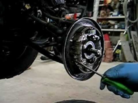 It’s ok to pressure wash your machine to clean it after a muddy ride. Just be careful around the bearing seal and hub assembly area. The pressure washer can push water into the bearing making them wear out faster.
Most of these steps will be the same, except you will be dealing with the hub assembly to replace the bearings. Also, you will want to freeze the new bearings before replacing them in the hub.
To remove the old ones the process will be the same also. Use a long punch or other tool to remove the old wheel bearings.
Some models will have a snap ring clip holding the bearing in place. You can easily remove this though with a pair of snap ring pliers.
Use a heat gun to warm up the hub assembly where the new bearings need to go.
Take the new bearings out of the freezer and press them into the hub. You can use the old bearings or a large socket and hammer to help push the bearings in.
Put everything back together the same way you took them apart and you’re good to go.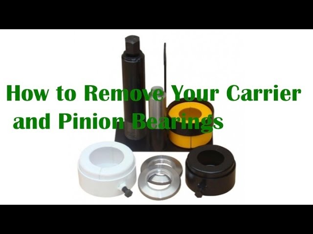 Remember to use all new cotter pins to keep things tightened down the way they’re supposed to be.
Sharing is caring!
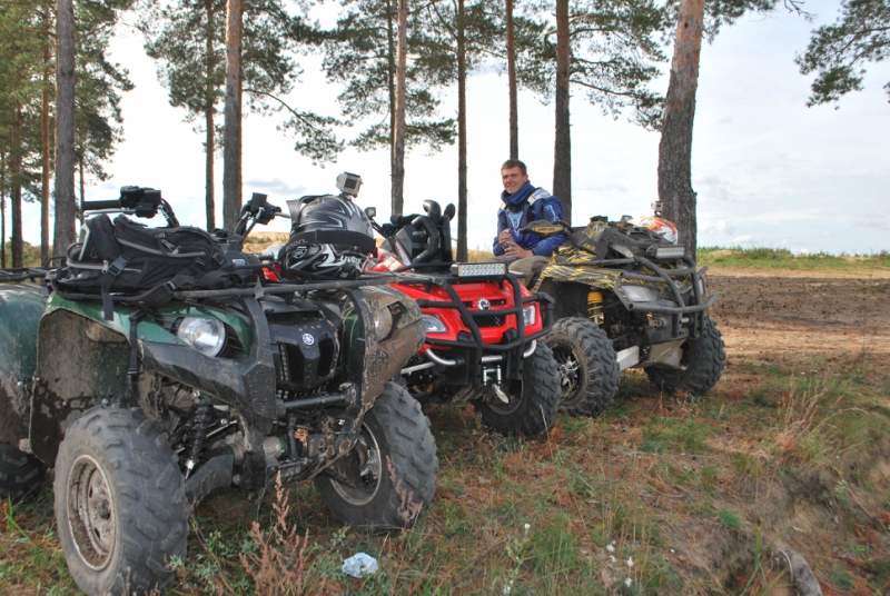
While riding, a young rider can put a lot of stress on their ATV. As a result, various breakdowns are not ruled out, some parts fail. Each of them is part of a well-functioning mechanism, without which the entire system cannot work correctly. If desired, many breakdowns can be eliminated on their own, without contacting a car service. Your child's ATV may need to be repaired if one of the following parts fails:
These are the most common breakdowns, in the event of which it is necessary to repair a children's gasoline ATV.
The rear axle is subjected to significant loads during driving, especially if there is a second passenger in the seat above it.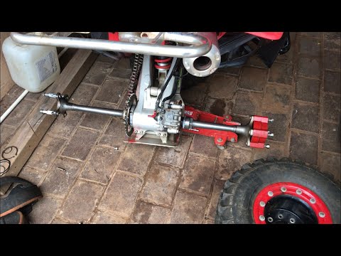 On children's models, axle failures occur much less frequently than on ATVs for adults. But if a child likes to carry passengers, jump, the likelihood of a rear axle failure increases significantly. nine0003
Before the element completely fails, when driving, you can hear a rattle, tapping or hum, sometimes the rear wheels begin to jam, and play appears on the wheelset. The reasons for such a breakdown can be:
To carry out repairs, the ATV must be jacked up. You will need to perform several sequential steps to repair the rear axle:
The rear axle can be fixed with different bolts and nuts. They will need to be unscrewed to free the sprockets. The axis is carefully knocked out, and the seals and bearings remain inside the pendulum housing. After that, it will be possible to replace any part of the rear axle assembly. nine0003
First you need to inspect the seals, hubs, brake calipers. All moving parts are generously lubricated with oil recommended by the manufacturer of the ATV model. It is worth considering that when the axle is knocked out of the pendulum, the probability of its breakdown is not ruled out. Also a common mistake during repairs is an overtightened bearing or an incorrectly assembled brake caliper.
To carry out repairs, you do not have to use special equipment, you can get by with improvised tools. You only need to purchase the appropriate parts that require replacement. Do-it-yourself repair of a children's ATV will not be difficult if a breakdown occurs in the area of \u200b\u200bthe rear axle.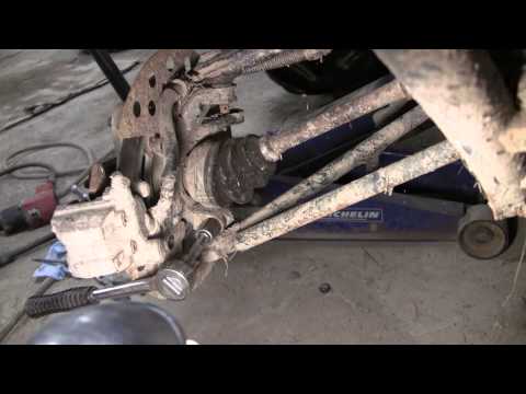 nine0003
Sooner or later the plastic parts of the ATV will have to be changed. If a crack appears in the material, you need to heat it with a 100 W soldering iron. To do this, the part must be carefully removed in order to warm up the deformed place on both sides.
Dents and chips can be repaired with suitable material. To do this, you need to purchase a fine-mesh stainless steel mesh. It is reliably soldered into the structure of the material when heated. The use of a mesh will avoid cracking of the plastic and will help to securely fix the junction on the fault. nine0003
Next, you will need to use "liquid plastic" or resin, which is poured into the cavity. The same principle applies when replacing large areas of damaged plastic. But in case of serious damage, the material will have to be taken from the donor ATV. After such work, the surface is treated with sandpaper, and painted in the color of an ATV.
The ATV owner may encounter a situation where, after a long period of inactivity, the engine will not start.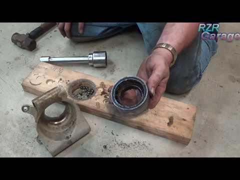 Sometimes this happens after a cross-country race. You might think that an expensive engine repair will be required, but this is not so. You need to pay attention to other systems, for example, the presence of gasoline in the fuel tank. It is also worth checking the battery, it may be discharged. nine0003
If there is no petrol in the fuel tank, this is not always the fault of the driver, for example, there may be a leak in the fuel line. The battery may be discharged if the user forgets to turn off the appliance.
If there is fuel in the tank, but it does not enter the engine, then the problem is in the pump. The hardest thing to fix the problem is if the piston system is worn out. There will be no compression in the engine, knocking may appear, and the whole system will not work as it should.
If the speed decreases, there is a smell of burnt rubber, and the variator belt is slipping, it's time to replace the element. The service life of this part is different for models, so it is almost impossible to predict a problem. The life of the component depends on the driving style and the load on the equipment.
To get to this part, you will need to remove the cover from the transmission. You should definitely check if all the screws have been removed, if there are any hidden latches on the variator. When the cover can be removed, the tensioned belt will become visible. You need to find the fixing bolt and loosen it. Once the pulleys are apart, the belt can be removed. nine0003
It is also recommended to inspect the surface of the transfer device. If it has scuffs in only one area, you need to find a bias in the variator system. To eliminate the imbalance, it is necessary to compare the places where the defect appears with the teeth.
A new belt is installed in its place. It must be well tightened by fully tightening the screw. It is necessary to create the same tension as the belt drive made by the ATV manufacturer. Further assembly is carried out in the reverse order. By starting the engine, it will be possible to evaluate the quality of the work performed.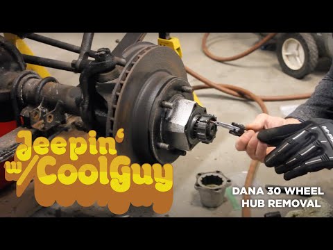 nine0003
During maintenance, check the condition of the oil seals, add oil to the system if necessary, and perform other technical tasks. Regular maintenance will improve the performance of the equipment and extend its life.
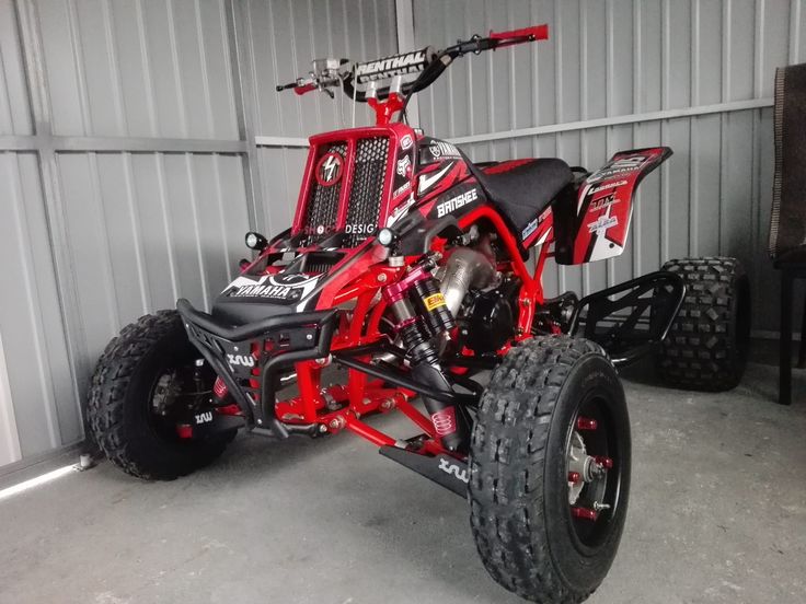
Nothing in this world lasts forever, but some Chinese products simply surprise with their “durability”. I will talk about my experience of upgrading a children's ATV.
What we have: a KL-789 children's ATV with minor malfunctions, some free time and a desire to stick an arduino lying around there.
What we want: something that lasts longer than one month, preferably with improved performance.
The ATV has two 12V RS550 commutator motors, with a shaft speed of 19300 rpm at idle, connected to the rear wheels with a diameter of ~30 cm through gearboxes with a gear ratio of ~131. Simple math says that the maximum speed of this vehicle should be 19300/131/60 * 3. 14 * 0.3 = 2.31 m/s or 8.3 km/h. In practice, he travels at about 7 km/h. During the selection of new components, I struggled with the desire to make the maximum speed, and the fear that this would be too dangerous a transport for children. Therefore, it was decided that he should go 1.5-2 times faster. In addition to engines, I was not satisfied with it:
 Section 0.75-1 sq. mm, which with rated currents of 20A are heated to a significant temperature
 Those. I was not satisfied with absolutely all the electrics. After some thought, it was decided to use:
 0, as the controller of all this
 In addition, to reduce the rumble of plastic wheels and improve the smoothness of the ride, 4 tires 12.5 "for baby strollers were bought, after which they were slightly modified with a clerical knife, and then they were pulled onto the wheels of an ATV and fixed with self-tapping screws:
When everything arrived, a prototype was assembled on its knees, it turned out that the engines even without load heat up to 70 degrees in 3-5 minutes of operation, I had to buy two coolers for them, and the regulators, on the contrary, even with the fans turned off, do not heat up ( looking ahead, on an ATV under load, they also do not heat up). Because we have two motors on two different sides, it was necessary to solve one more problem - sensory motors spin only in one direction.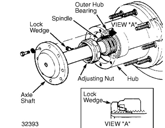 Initially, it was planned to disassemble one motor and turn the sensor 180 degrees in it ... but reality has shown that this cannot be done with little bloodshed. Moreover, during experiments with the sensor and timings, one of the regulators partially burned out, as a result, I abandoned the sensor and connected them as ordinary BCs. The sensor itself consists of three Hall sensors that monitor the position of the rotor, and a temperature sensor. It was decided not to leave all this economy, but to connect it to the MK and use it as an engine temperature sensor, an engine speed sensor, and later, knowing the gear ratio, as a speed sensor. nine0003
The pwmservo library was somewhat puzzling, it is designed to control servos (regulators in my case) through hardware PWM, with an accuracy of 1 degree, only 180 states, and the “forward” direction is only half the range, i.e. 90 states. It seemed to me that this was not enough, I had to edit the library to the detriment of the cross-platform arduin (it turned out only for controllers with 16 MHz), the result is 1000 states in each direction (the unit is equal to 0. 5 μs of the PWM duration, PWM from 1 to 2 ms). nine0003
After the work "on the knee" was more or less debugged, all this equipment was installed on the ATV:
Photo
Engine + gearbox:
Inside a small creative mess of wires (just threw all the wires inside, I wanted to test faster, later brought to human form):
Because the power turned out to be more than 500 W, it was necessary to limit the rate of increase of the gas, if you sharply turn the gas to the maximum from a place, the power will increase smoothly, and will reach its maximum in about 3 seconds. I am sure that without this there would be an effect of instant overturning. nine0003
In general, here is a telemetry video recording from the phone screen, everything is visible there, only due to a slightly glitched speed sensor in the left engine (left green column), the speed data is slightly underestimated, the maximum speed achieved on fresh batteries is 18 km/h
Values of the columns: blue - engine temperature in degrees, green - engine speed in rpm, orange - power supplied to the engines in conditional numbers from 0 to 1000, gray - throttle position.
And this is how it goes:
I wasn’t dragged away… it’s slipping, but I rode the quad bike itself, and judging by the telemetry, it absolutely doesn’t care who is on top
In the first video, a crunch is heard at the start. On the first evening, the gearboxes completely failed. The problem turned out to be that the gearboxes consist of nylon gears rotating on a 9 mm steel axle without bearings, so the friction force of the gears turned out to be so large that in one gearbox the middle just melted out in the gears and the alignment was lost. In another gearbox, the gear was welded to the axle, and the axle began to rotate in the housing and melt it, as a result of which the gear also lost alignment. nine0003
To solve this problem, you need:
The new axles are 5mm, so I had to print on a 3D printer bushings with an outer diameter of 9 mm (like the old axles), and an inner diameter of 5 mm, in order to be able to install the new axles in the old gearbox housing, 11 mm holes were drilled in the gears with a depth of 5 mm with both sides (bearing seats).