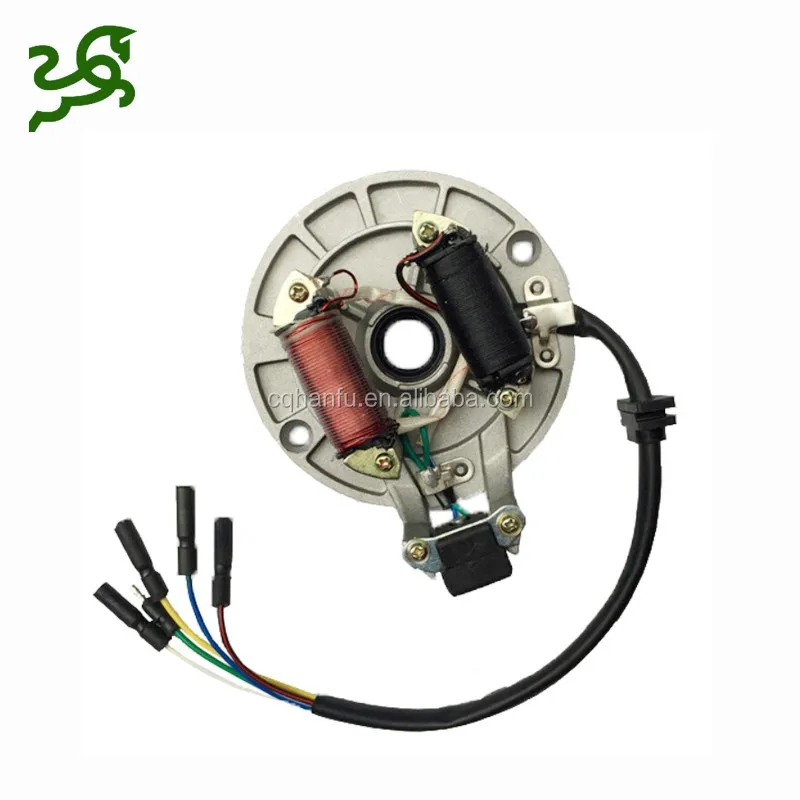
Your ATV’s stator is an important part of the electrical system, along with the battery and regulator. If you have some kind of electrical problem, particularly a failure to charge, the issue is likely with one of these components.
An ATV’s stator recharges the battery while the machine is in use, like an alternator in a car. Your ATV may have a single-phase stator, a three-phase stator, or a bar coiled stator, all of which look differently. Most modern ATVs use a three-phase-stator as these components produce more electricity.
Testing the stator gives you an idea of where to start. If the problem is with the stator, someone can fix it. Here’s how to test your ATV’s stator and fix it if it turns out to be a problem.
Your ATV’s service manual will contain the information you need about your type of stator. It should also illustrate any extra components on your particular model. No matter the type of stator, testing it is a similar process.
Before testing the stator, however, you may wish to take a few additional steps. First, check the battery by placing it on a different charger. Take the time to look for corrosion, and clean the connectors and wiring. If none of those actions fix the battery charging issue, it is time to test the stator.
To test the ATV stator, you will again need the multimeter. You will first perform a static test, or a test done without the engine running and without the stator attached to the ATV. Make sure the ATV is off when you disconnect the stator.
With your multimeter set to ohms, get to work resistance testing each circuit. Connect the multimeter leads to the terminals in the stator’s electrical connector, testing between pins 1 and 2, 2 and 3, and 1 and 3. Compare the multimeter reading to what it should be in your service manual.
The next test is to determine if the stator is shorting out to the ground. For this you will put one meter lead in the connector and the other on the stator body.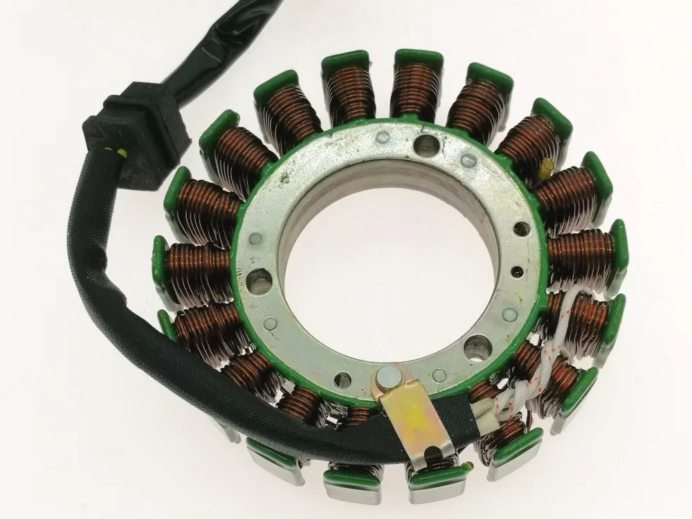 The correct reading in this situation is OL, or open line. If you see another reading, the stator has a problem. Perform this measurement for each coil/winding/phase.
Another test is the dynamic test, this time with the motor running. This will only work if your battery has some charge. You must set your multimeter to AC voltage for this measurement. You will likely need a friend to help.
With the engine running, measure between coils/pins by connecting the multimeter lead to the terminals in the electrical connector for the stator. Again, measure between 1 and 2, 2 and 3, and 1 and 3. You are looking for a positive reading.
You can also re-do this test with an increased engine RPM. In this case, you are looking for the reading between terminals to increase as the RPM increases. A voltage reading that remains the same from the static test to the dynamic test indicates a problem.
Fixing a stator usually involves unwinding and cleaning the original stator core, then rewinding it with a machine or carefully by hand. It starts with looking at the coil heads for damaged or burned wires, then cutting out the protective rubber coating from damaged coils. Note which direction the wire wraps around the coil head, then remove terminal clips from the base with a screwdriver.
The next step is to unwind the damaged wire. After this, you will clean the surface of the stator head with fine-grade steel wool. Wipe it clean afterward. The new wire should be the same gauge as the old, wrapped around the heads in the same direction as before. There should be no gaps between the wire wrappings, and terminal leads will require an additional length at the top and bottom.
Crimp the terminal leads to those one-inch lengths using pliers, and attach the leads to the stator with a screwdriver. Then, test the functionality of the repaired stator with your multimeter in ohm setting mode. If all looks good, coat the new wiring with liquid rubber and allow it to set.
If repairing a stator is outside of your skillset or you would rather get a new stator, a full replacement is possible. You can either perform the installation yourself or outsource the whole process to a reliable ATV repair expert.
Disclaimer: While we endeavor to keep the information on our blog up to date and correct, Maxtrade (Coolster) makes no representations or warranties of any kind, express or implied about the completeness, accuracy, reliability, suitability, or availability with respect to the website or the information, products, services, or related graphics contained on the website for any purpose. Any reliance you place on such material is therefore strictly at your own risk.
Resistance Test Make sure your ATV is off. Disconnect the stator cable. You should see the three wires of the same color running out of the stator to the connector. Turn the multimeter to ohms.
How to Test the Stator in an ATV
Step 1. Pull both of the stator’s pin-connector plugs from the wiring harness with your hands.
Step 2. Set a multimeter to the DC “ohm” or “1X” or setting.
Step 3. Test each circuit on each plug separately. Touch either of the meter’s probes to the male pin on the first plug.
Step 4. Move the probe from the first female socket to another female socket on the same plug.
What is an ATV stator? The stators found in motorcycles, ATVs, and UTVs are generally 3-phase stators. These consist of three separate windings wrapped around a series of points that circle the unit, with the ends of the three windings leading to an electrical connector. A stator test is either static or dynamic.
What is an ATV ground test? ATV stator – Ground Test Setting a multimeter to Ohms, touch the negative wire to the ground and alternate the positive wire between every lead of the stator’s connector. If you have any reading different from OL (Open Loop), you have a faulty stator.
What is a static stator test? When you have a problem with the electrical system in which the engine on your motorcycle, ATV, or UTV won’t run, you’ll have to do a static test. The static stator test involves measuring from coil to coil — or phase to phase — within the stator, and also measuring from each coil/phase to ground.
How do you know if your ATV has a bad stator? But, how do you know if your ATV has a bad stator? If your stator is bad, the battery of your ATV will not charge while the ATV is running. This can be caused by several other problems, however, so the only way to be sure that your stator has gone bad is to perform a series of tests using a multimeter.
Table of Contents
Holding the plastic handle of the screwdriver, bring the metal area of the screwdriver close to a metal part of the engine, being careful not to touch it. Have someone start the mower. If you don’t see a spark between the screwdriver and the engine, the magneto is bad.
Coil Failure The voltage generated across magneto coils is quite high, in the order of 20,000 volts if no spark plugs are in place. … The high voltage will simply arc across the gap. The gap will widen as the wire ends melt further apart and soon the adjacent turns will be affected so the coil will eventually fail.
The rectifier is part of the charging system. If you put a freshly charged battery in your motorcycle, and you have a bad rectifier, it won’t stop your motorcycle from starting, but your battery wouldn’t stay charged.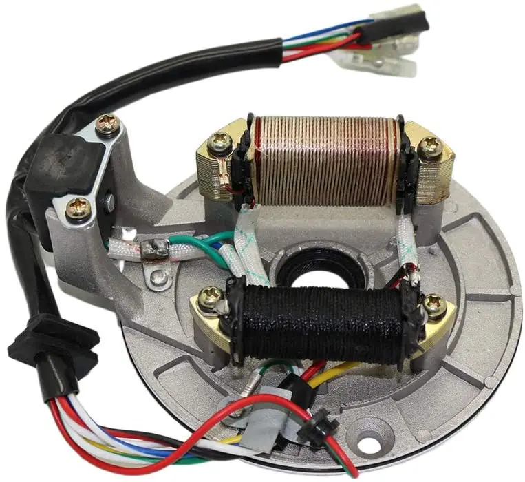 The regulator/rectifier on your motorcycle performs two functions.
There are a few things that may cause a stator to fail. Too heavy of a load when operating accessories (winch, heated grips, headlights, etc). If working several of these items at one time (plowing/pulling/possibly stuck at night) you would overload the system. This could cause either the stator or rectifier to fry.
Stators do not go bad from sitting unless the mag housing is full of water.
A bad diode in a rectifier will dump AC current into a system. The AC current heats up the stator and the heat destroys the insulation and ultimately carbonizes it turning it into a low resistance brick.
Insert each probe into a stator socket. You should read around 0.2 to 0.5 ohms. If you show an open circuit with the “Open” or infinity reading or have higher resistance, then the stator is bad and you must replace it. If these tests all produce positive results, then the stator itself is good.
– Pull both of the stator’s pin-connector plugs from the wiring harness with your hands; the two plugs each have one male pin and multiple female sockets. …
– Set a multimeter to the DC “ohm” or “1X” or setting.
First, the diode can burnout and cause the battery to drain. You won’t have any trouble diagnosing the faulty regulator rectifier if the battery is the cause. You’ll note signs right away like poor starts, fluctuating meter readings, and dimmed headlights. around 13 volts, the bike will start to drain the battery.
You won’t have any trouble diagnosing the faulty regulator rectifier if the battery is the cause. You’ll note signs right away like poor starts, fluctuating meter readings, and dimmed headlights. around 13 volts, the bike will start to drain the battery.
Just like that, without a minimum knowledge of electronics, at least at the level of the school curriculum (like mine) and the simplest multimeter tester - you won’t be able to check the generator, don’t even dream. Before undertaking such work, you should at least be able to use a tester and understand that the current can be AC or DC, know what an electrical impulse is and what resistance is.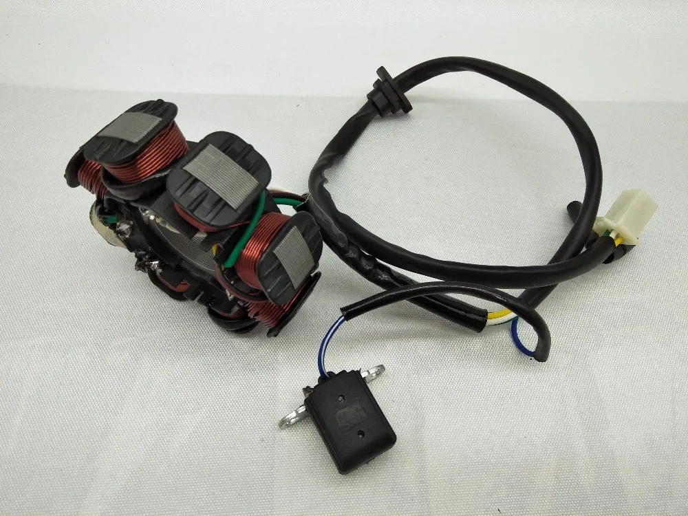 Do you know all this? Did you have a tester in your hands? If so, then let's not delay.
Checking the generator's performance - you should start with measuring the voltage that the generator should actually generate and transmit via wires to consumers. We look where the wiring harness from the generator comes out of the engine - we move along it until we reach the connector with which the generator is connected to the on-board network of the scooter.
On the vast majority of scooters, the alternator connector looks something like the picture. In the common connector, there is one plug and two wires that are connected to the scooter's on-board network through round terminals.
The plug combines the connectors of the two main windings of the generator: The working winding (yellow wire), which ensures the operation of the headlights, turn signals, lights and other consumers. And the control winding (white wire), the control winding provides voltage control in the main winding of the generator.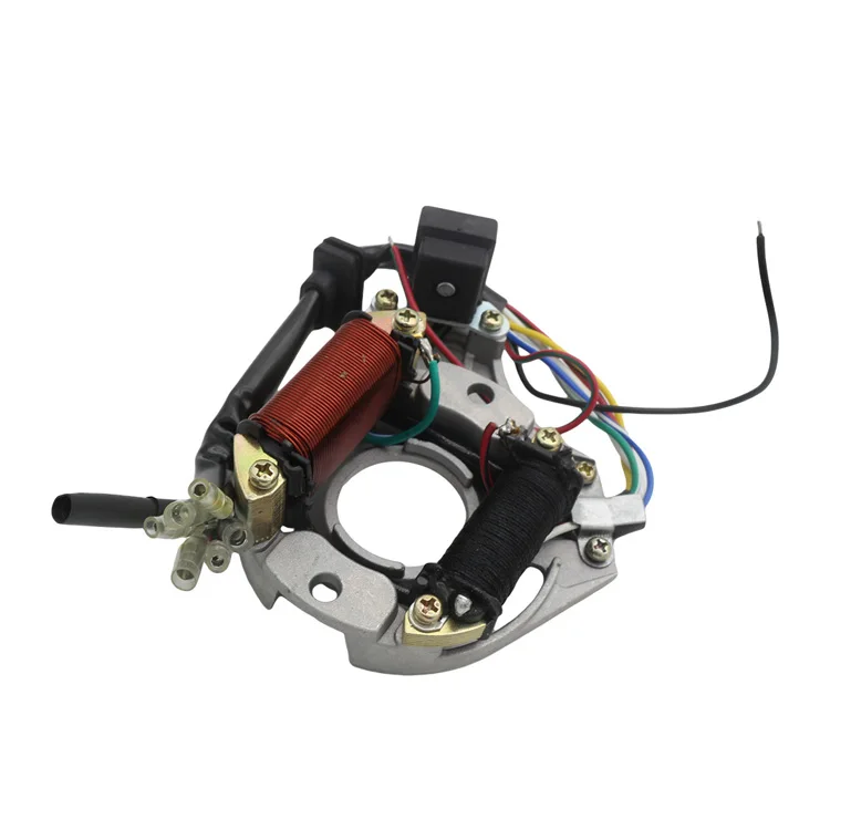 That is, when the voltage in the working winding of the generator rises above the specified limits, the voltage regulator relay supplies current to the control winding of the generator, due to which the voltage in the working winding of the generator drops to a predetermined limit. When the voltage drops, the reverse process occurs.
In this generator, the main windings are wound with thick copper wire on six coils.
The third winding of the generator, which is commonly called high-voltage or induction and magnetic induction sensor of the generator, is connected to the scooter's on-board network through round terminals.
High-voltage winding of the generator - provides the generation of high alternating voltage (the voltage in this winding can reach 160 V or more), which directly enters the switch where it is rectified, then accumulates in the capacitor and at a certain moment is supplied to the ignition coil in the form of a pulse.
In this generator, the high voltage winding is wound with thin copper wire on two coils.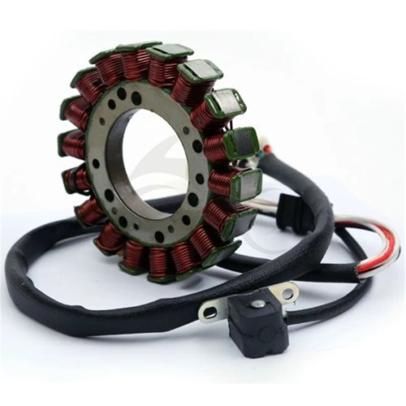 The coils of the high-voltage winding are carefully insulated on the outside.
There are generators in which the high-voltage winding is wound on only one coil.
A small clarification: ignition systems in which a DC CDI type switch is installed, the high-voltage winding does not participate in the formation of a spark charge on the spark plug, so there is no point in checking it. Scooter manufacturers install a generator with a high voltage winding, but do not use it (meaning ignition systems with a DC CDI switch). It is simply wound on the generator and that's it. I will say more: due to the fact that the winding is not loaded with anything during the operation of the generator, over time it simply burns out.
An example of a generator, on two coils of which a high-voltage winding is wound in no way involved in operation. I checked this winding - the tester showed an open circuit, which confirms the above.
The resistance of the supply winding of the generator is always greater than that of the other windings. The wire coming from the inducing winding of the generator is almost always red-black.
Magnetic induction sensor, when a special ledge on the generator rotor passes by, generates a sign-alternating pulse that opens a thermistor through which the switch capacitor is discharged to the ignition coil.
The sensor itself
The ledge on the generator rotor
The wire coming from the magnetic induction sensor almost always has a white-blue color.
A small educational program: Merchants and collective farm tusks, magnetic induction generator sensor, CDI ignition systems - called the Hall sensor. My relatives ... Maybe that's enough already? .. Where does this illiteracy come from? .. The magnetic induction sensor of the generator, the CDI ignition system, namely, this system is discussed in this article - has nothing to do with the hall sensor! And don't listen to these hucksters and "gurus" who claim otherwise...
The test itself
Switch the tester to the AC measurement mode (ACV) on the range of 200 V and no less. Remember that the voltage of the inducing winding can reach 160 V or more, so the measuring range of the voltage of the inducing winding must be at least 200 V.
red wire) of the leading winding of the generator. We turn on the ignition, and turn the engine with a starter. A fully serviceable inducing winding should give approximately the following values.
The pulse generated by the sensor is very weak, so we switch the tester to the ACV measurement mode on the 2 V range. Measuring the pulse from the sensor in a higher range may not give a result, since the tester may simply not catch it. For this purpose, use only a tester with a range in the AC voltage measurement mode of not more than 2 V.
We do everything exactly the same as in the first example. The pulse from the sensor should give approximately the same values.
By analogy with the first two examples, we measure the voltage in the working winding and the control winding. We put the tester in the mode of measuring alternating voltage (ACV) in the range of 200 V and carry out the measurement.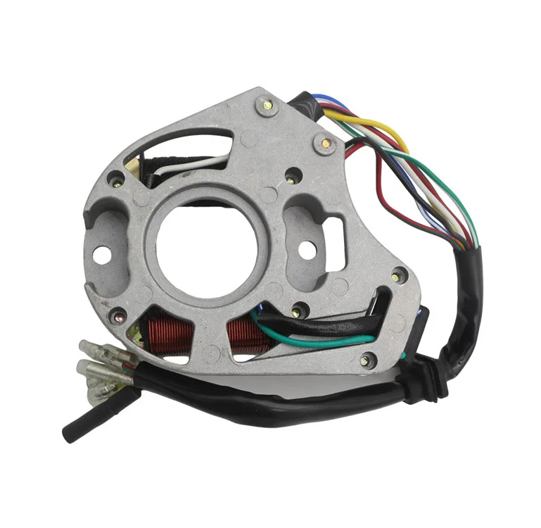
Well, what did you measure? .. Do all windings generate current? Or not all? .. If any winding does not produce current, then if you want it or not, you will have to remove the generator and check it in more detail. But if the windings generate a current of about the same magnitude as in the pictures, then this means that your generator is in perfect order. Something like this…
In-depth check
We lay the generator so that the generator winding leads are accessible to you. We determine the ends of the conclusions of all the windings of the generator. Finding the ends of the windings is very simple: we look at the color of the wire that is soldered to the terminal block and determine what kind of winding it is.
I marked the ends of the windings with arrows. I selected the arrows by color in accordance with the color of the wires soldered to the terminal block. The green arrow marks the terminal block on which the ends of all windings are soldered - this is the ground terminal block.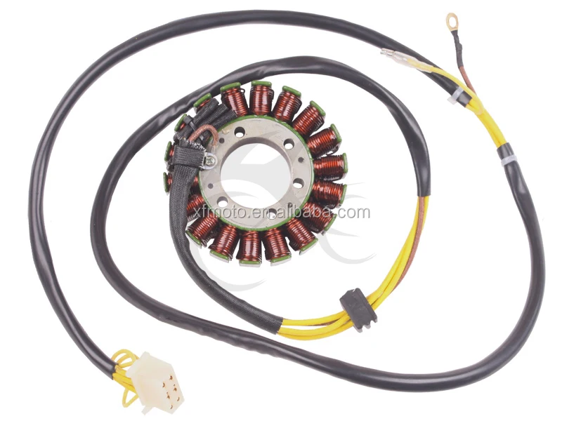
We switch the tester to the continuity mode, take any wire from the common harness, connect any tester probe to this wire, touch the terminal block to which this wire is soldered with the second probe. The tester should beep and show zero resistance.
If the tester is “silent”, shows numbers instead of zeros, then this means that somewhere there is a wire break or poor contact between the end terminal and the wire. Inspect the wire carefully for a break and, if necessary, replace it with a new one. The remaining wires, including the sensor wire, are checked exactly according to the same principle.
After checking the wires, we proceed to check the generator windings for open circuit and interturn circuit. We switch the tester to the continuity mode, touch the generator case with any probe of the tester, touch the end of the wire of any winding or terminal block with the second probe.
The high-voltage winding in continuity mode should show approximately this resistance value.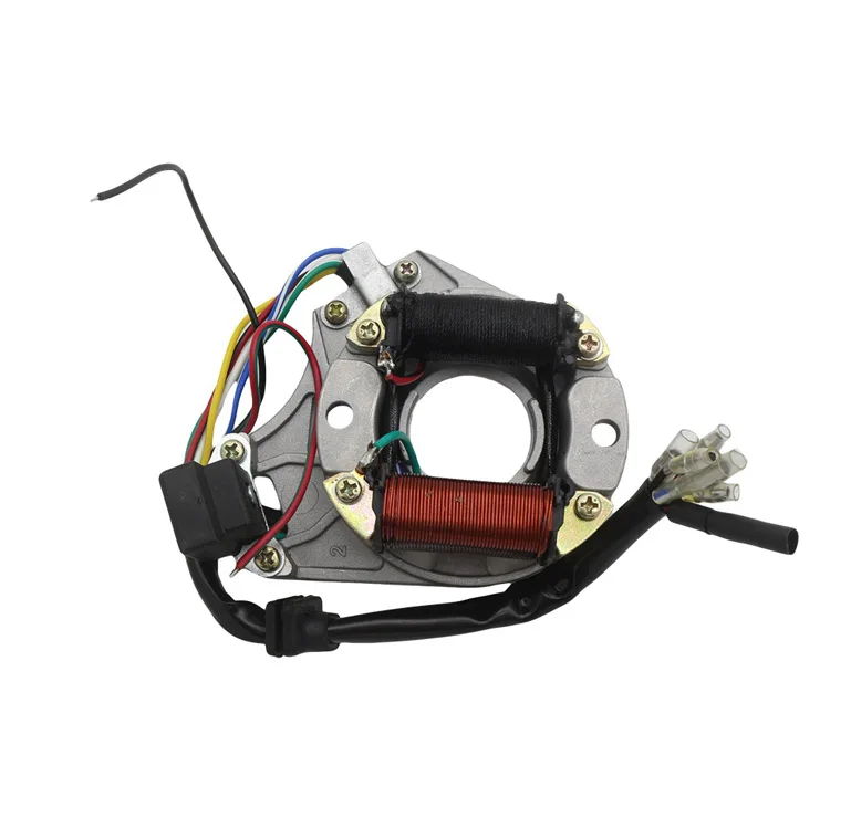 If the high-voltage winding did not show resistance or showed but little resistance, then this means that somewhere there is an internal open circuit or an interturn short circuit. You understand that such a malfunction is not “treated”.
When checking the remaining windings, the tester should emit a beep, the resistance of the working windings is very small, so most likely you will see only zeros on the tester display. If the tester did not emit a signal, then this means that somewhere there is an internal break. Such a malfunction cannot be "treated".
We put the tester in the continuity mode, touch the sensor body with any probe, touch the sensor wire or the terminal on the body to which the wire is soldered with the second probe. The resistance of the sensor winding should be approximately within these limits. If there is little or no resistance, then replace the sensor with a new one.
The reason lies in the banal discharge of the battery.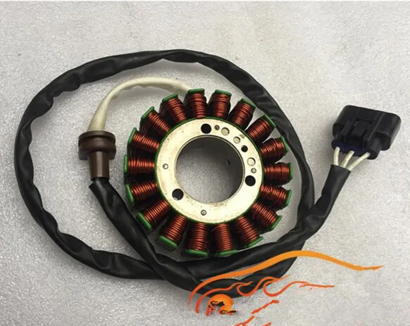 Such is the peculiarity of CDI ignition (especially Chinese and especially Kazumovsky) that sometimes the battery energy is even more than enough to confidently crank the crankshaft, but there are no flashes in the cylinder. The reason is that at the moment of starting there is a voltage drop, there is not enough energy to charge the CDI capacitor and there is no spark, or it is very weak. At the same time, many are confused by the fact that when checking "in air" there is a spark, but in a cylinder under pressure, where the conditions for sparking are much worse, there is no longer a spark and, accordingly. there is no start even though there is some kind of spark during the check. In such a situation, you just need to charge the battery!
Poor contact in the flat connector of the ignition coil can also lead to symptoms similar to malfunctions in the operation of the carburetor (failure when pressing the gas, the possibility of the engine running only at idle, pops in the exhaust pipe).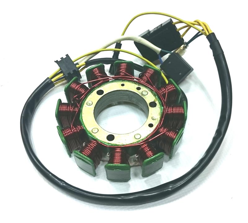 It is treated simply by crimping the terminal (or even better, replacing the terminal with a more rigid one), I recommend that you carry out the procedure at the stage of preparation for operation, because in the event of such a malfunction, it is floating in nature, similar in symptoms to other breakdowns possible for the Otto internal combustion engine, and it can get out at the most inopportune moment. Starting around mid-2011, the terminal was replaced with a more reliable connection.
If, despite the crimping of the terminal, symptoms of late ignition appear (smell of gasoline from the exhaust, pops in the muffler when the gas is released), then it is necessary to check if metal particles have adhered to the inductive spark moment sensor . Since the sensor is located under the same cover with the bendix and the flywheel gear, the chips from these parts stick to the sensor with magnetic properties, as a result of which the signal front is knocked down, the CDI unit incorrectly determines the TDC and engine speed, which leads to errors during sparking. I repeat, the symptoms will be similar to a malfunctioning carburetor and an excessively rich mixture (incomplete combustion of fuel, a strong smell of gasoline from the exhaust, pops in the muffler when releasing gas). As I already wrote, with such signs, the fuel line should be returned, and if this does not help, leave the carburetor alone and check the ignition system! But first of all, we look at the sensor and clean it from adhering metal particles (for example, using adhesive tape).
Ignition switch (CDI control unit)
The CDI unit can "burn out" (completely fail) for two reasons. Firstly, due to the unstable operation of the standard voltage regulator. It is better to replace it with a similar part from Dinli or CFMOTO (by soldering the connector). Secondly, if you mix up the battery terminals. Of course, we are talking about a charged battery (if the battery is dead, then there is nothing to burn the electronics from). To avoid burnout due to reverse polarity, you can supplement the power supply circuit of the CDI unit with a diode.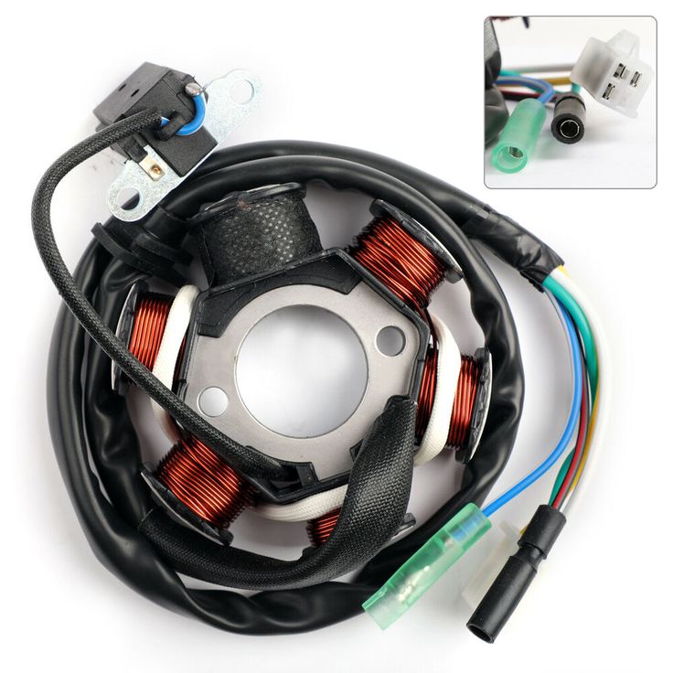 It is strange that this is not done by the manufacturer (although this may not have been done on purpose - to sell CDI blocks to inattentive 500K owners). Well, only replacing it with a quality one can save you from the poor performance of the voltage regulator.
If the spark has disappeared, I recommend the following algorithm of actions developed by experience and tested by time.
First things first quick test of the ignition unit. You need to check if the wire going from the block to the coil is sitting on the ground. To do this, disconnect the wire from the coil (if it is with a terminal) or disconnect the coil from the ground (to do this, you need to remove it) and check if it is closed to ground (with a tester or simply with a probe lamp). If it is closed, then the ignition unit must be replaced. If not (although it will probably be “yes”), then we continue the check.
It should be noted that the ignition coil, the spark moment sensor and the candle fail so rarely that it is unlikely that anyone will need the information contained below, but, nevertheless, I will write it down, since anything can happen on Kazuma.
Just in case, we change the candle to a known good one (preferably a new one). It is clear that it most likely will not help (unless the candle has traveled many thousands of kilometers), but it will eliminate doubts, and also allow you to check other components as reliably as possible. In this case, in no case should the ignition be allowed to work without load (check the breakdown for mass) - spark test is carried out exclusively with a cap of high-voltage wire dressed on a well-grounded candle.
Ignition coil, wire and spark plug cap
Next, check the coil, wire and spark plug cap.
The high-voltage wire is attached to the coil using a screw poured into its body (on which it is screwed with its central part, which fixes the wire and also allows you to transfer the discharge from the screw to the current-carrying core). To check, you can unscrew the wire from the coil and measure the resistance. It should be at the level of 5 kOhm (5. 000 Ohm), which will give the resistor in the cap. The wire is also screwed into the cap on the screw, the red sheath is just a sealant, inside there is a hard tip with a resistor. If the wire is in order, go to the coil. The resistance of the secondary winding should be 6 kOhm (6.000 Ohm), we measure between the high-voltage output of the coil (in our case, a screw) and the mass (“ears” with which the coil is attached to the frame and to which the ring terminal of the green wire is attached). In principle, you can check both the wire and the primary winding at the same time: if you do not remove the wire from the coil, then the resistance between the mass of the coil and the candle cap should be about 11 kOhm (11.000 Ohm). The resistance of the primary winding should be no more than 0.3-0.4 Ohm (tenths of an Ohm!), We measure between the flat terminal (to which a positive impulse from the switch comes through the yellow-black wire) and the mass of the coil. The parameters are checked on two serviceable coils.
 If the data of the coil being tested does not match the above, the coil should be replaced, even if it produces some kind of spark. Under pressure in the cylinder, the conditions for sparking are worse than in air (at atmospheric pressure), and there may no longer be a spark, or the spark will be unstable and insufficient for normal ignition of the mixture. The ignition coil can be replaced not only with the original one, but also with a suitable one from other quadras (for example, Hisun, etc.), as well as with a car one (see below for connecting the latter).
In case of failure of the ignition coil , you can install an automotive one, for example, from a VAZ 2108-09 (or from a non-contact ignition system of any other car).
We buy a coil for VAZ 2108-09 and the most common wires (come in a set, 5 pieces, red) - with a copper core. No “silicone” ones - they have a high-resistance current-carrying wire made of carbon fiber, CDI ignition can hardly handle this, and most importantly, there is no point in overpaying 10-20 times for unnecessary things.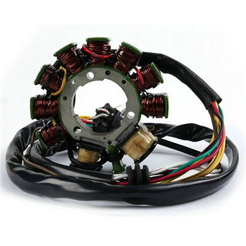
We take the central wire (which the basin should go from the coil to the distributor), cut off one end. We take our coil with wire and unscrew the wire from it. We connect the current-carrying cores of the VAZ wire and the 500K wire by soldering, reliably insulate (using heat shrink), and also, if possible, put a corrugation on the entire resulting cable, which we wrap with electrical tape (or again we wrap it with heat shrink) so that the BB cable does not lie anywhere directly with its insulation on the mass .
We connect the coil terminal going to the VAZ to the switch (K) with a negative wire (500K green with a ring terminal), the coil terminal going to the battery (B or just +) from the VAZ, we connect it to the output of the switch, which supplies the voltage of the capacitor to the coil (yellow-black wire coming to the coil, until mid-2011 - with a flat terminal).
It must be connected in this way, because in the CDI system the coil does not work as an energy storage device (unlike the "car" ignition system), but only performs the function of voltage transformation. That is: the coil must constantly sit on the ground, and when an impulse from the switch passes through it, it will simply give out a high voltage discharge to the candle (unlike the “car” connection, where voltage is constantly applied to the coil, and a spark occurs at the time of landing coils to ground).
Sparking moment sensor
If the part of the ignition system located after the CDI switch is fully functional, it is necessary to check the ignition moment sensor (crankshaft position sensor) for an open or short circuit of the winding:
The sensor can be checked indiscriminately with a tester! The working resistance is 110-130 ohms, you need to measure on the wires that fit the switch blue / white (blue comes out of the magneto) and violet (green comes out of the magneto)!
If the sensor is faulty, then you can put a suitable mount from any scooter (150-200 rubles). The original sensor is sold only complete with a magneto (3500-4000 rubles and more).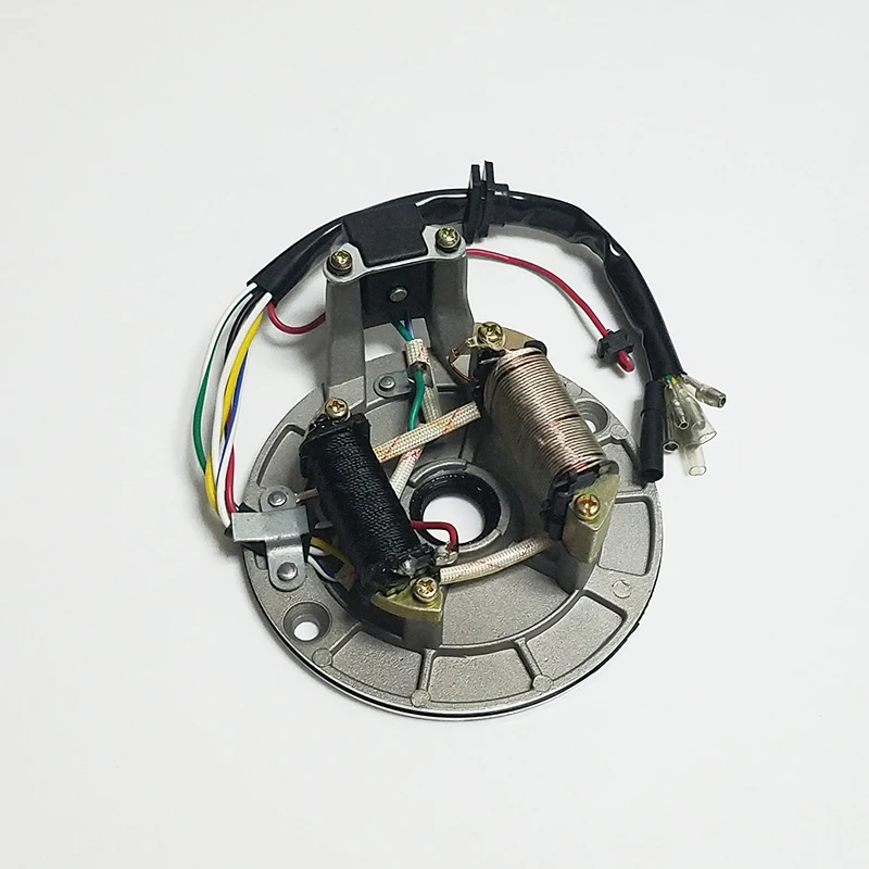
Again about the switch
With a good sensor, the ignition switch remains again (a new one costs about 2000-3000 rubles). It is possible to install a switch from a Suzuki Lets scooter, you just need to solder the connector, however, the used AlekseyL (see the report at the link above) is very difficult to find the block version (with an external connector) (at least I did not succeed), and when installing another modification (common, with a connector filled into the body), the ignition turns out to be extremely early (there are back blows to the piston). It may be possible to coordinate the operation of our sensor and the common CDI unit from Let's, but I decided not to risk it by choosing the sparking time by touch, but set it to 500K transistorized ignition with microprocessor control , for a report on the installation of one of the possible options for such an ignition system, see HERE.
The best option is to replace the ignition unit with a design unit Grishko Alexander : it does not require either replacing the sensor or installing a car switch (discussion HERE). He himself took part in the tests. I recommend!
Report AlekseyL about this ignition system, see HERE.
Just in case, I additionally give a description of the pinout of the original ignition control unit and the image of the connector (cut off in the photo):
AlekseyL wrote:
If anyone is interested, here is the pinout of the switch connector:
Pinout from left to right, connector key at the bottom!
1 - sensor (blue wire)
2 - jammer (white / black wire)
3 - minus (black wire)
4 - ignition coil (orange wire)
5 - sensor (green wire)
6 - plus (red wire)
Please note that the colors of the wires in the switch connector change to others. For example, position “4” - an orange wire goes from the switch to the connector to the coil, but yellow wire with a black stripe (etc.) comes to the coil from the connector, be careful!
For clarity, I also provide a photo of the ignition harness connector (from the wiring side): However, it is possible to shift the COP by several degrees. To do this, you will have to remove the flywheel (and it is removed very reluctantly, it is not removed at all with conventional three-legged pullers), unscrew the screws securing the platform on which the “stuffing” of the magneto sits and try to tear off the platform from the engine housing (planted on sealant). Now, by turning the platform within the slots for the mounting bolts, you can slightly shift the sensor relative to the flywheel: if you turn it counterclockwise, the ignition will become earlier, if clockwise - later. However, such an adjustment allows you to move the sensor at very small angles, which will not lead to any noticeable changes in operation. A simpler option is to pierce the ears of the sensor, but this will allow you to shift the UOZ by a ridiculous amount. As a development of the second method, it is possible to build a bracket and set a larger displacement of the inductive sensor.
But the most important thing here is that with a good ignition, adjustment is not needed, and with a faulty UOZ, it will float and no adjustments will help.