Delivery options and delivery speeds may vary for different locations
Sign In
or enter a zip code
Email * Password *
REPAIR & HOW TO
MAINTENANCE
TROUBLESHOOTING
GUIDES
TIPS & TRICKS
ALL ARTICLES WATCH VIDEOS ABOUT US SHOP PARTS CONTACT US
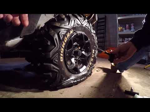
Whether it's a motorcycle, an ATV, or a UTV, it probably has some kind of starter relay or solenoid.
Your solenoid might differ from others and have more connections, but there are two basic tests you can do to evaluate your solenoid's health.
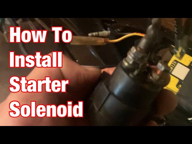
A starter solenoid is basically a switch that creates a contact point between the battery and the starter. When the starter button is pressed, it energizes the coil, which pushes a contactor to complete the circuit. This transfers DC current from the battery to the starter.
In the first diagram below, the starter button has not been pressed, so the circuit is not complete.
In the next diagram, the starter button has been pressed, and the coil in the solenoid has been energized. This pushes the contactor up and completes the connection from the battery to the starter motor.
Knowing how to test the solenoid on your offroad vehicle is an important step to troubleshooting starting problems on your machine. Here are some tests you can do to check the health of your motorcycle's starter relay.
Tools Needed - Motorcycle Starter Relay TestDepending on your unit, the tools you'll need to access the starter solenoid may vary.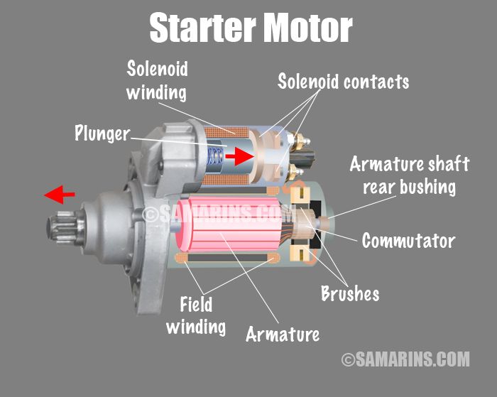 But these tools will help you regardless of what kind of unit you're working with.
This first test is designed just to see if the contactor is pushing up and completing the connection in the solenoid.
Step 1. The solenoid has two wires that normally connect to the starter button. There is no polarity on the solenoid, so it doesn't matter which side is which. You're just running current through it. Using back probes, connect directly from the battery to one of these wires. Complete the connection to the negative side of the battery first.
Step 2. Connect a second back probe to the solenoid. Then, connect it to the positive side of the battery. You should hear an audible "click" as the connector is pushed up to complete the circuit. If you don't hear it, the solenoid has gone bad. And if you do, move on to the next test.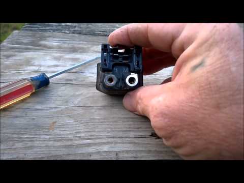
In some cases, even when the connector engages, the unit still will not start. That can happen when there's corrosion on the connectors inside the solenoid. This next test can help you diagnose this problem.
Starter Relay Test 2Step 1. Keep your connections in place from the first test, and simply disconnect the back probe from the positive terminal on the battery.
Step 2. Connect your multimeter to the main connectors on the solenoid and set your multimeter to a resistance test. Again, polarity isn't important. Just connect one clip of your multimeter to each side of the solenoid.
Step 3. Once connected, you should see "OL," indicating an open circuit.
Step 4. Connect the positive side of the battery using the back probe connection from Step 1. This will energize the solenoid and push the connector into position, completing the circuit.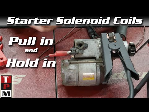
These two simple solenoid tests show you the basics of how to diagnose issues with your relay. First, check to make sure the connector is engaging and completing the circuit to the starter. Then, make sure the circuit to the starter is connected when the connector is engaged.
The starter relay is just one of many starting problems that can affect your motorcycle. Watch the video below to see how to diagnose multiple starter problems on a Honda CBR 600 motorcycle.
body
Delivery options and delivery speeds may vary for different locations
Sign In
or enter a zip code
Email * Password *
REPAIR & HOW TO
MAINTENANCE
TROUBLESHOOTING
GUIDES
TIPS & TRICKS
ALL ARTICLES WATCH VIDEOS ABOUT US SHOP PARTS CONTACT US
There are three types of starters fitted to motorcycles, ATVs and side-by-sides, and the steps below detail how to test each one of them.
Before bench testing a starter, make sure to:
The first type of starter has a starter motor and a solenoid incorporated into a single unit. The starter features a Bendix gear that engages with the flywheel in order to start the engine.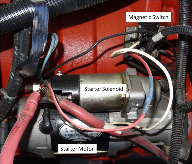 This type of starter is commonly found on side-by-sides, utility vehicles and automobiles.
The second type of starter has a separate starter motor and solenoid, but still features the Bendix gear that engages with the flywheel to start the engine. This type of starter is generally found on larger motorcycles and ATVs.
The third type of starter also has a separate starter motor and starter solenoid, but this starter engages with a reduction gear and one-way clutch to start the engine. It doesn’t use a Bendix gear. This type of starter is generally found on sports motorcycles and ATVs.
Testing a Bendix Gear Starter/Solenoid UnitThere are two nuts on the solenoid. The one furthest from the starter motor secures the wire coming from the battery, and the one closest to the starter motor secures the wire going from the solenoid to the starter motor. There’s also a spade terminal on the solenoid that connects to the wire from the ignition switch or push button, which triggers the solenoid to engage the Bendix gear.
1. Connect a negative jumper cable to the negative terminal of the battery and the body of the starter motor.
2. Connect a positive jumper cable to the positive terminal of the battery.
NOTE: The positive jumper cable is now live, so be careful not to touch the other end against a ground surface.
3. Touch the free end of the positive jumper to the spade terminal on the solenoid. You should hear a clicking sound from the solenoid, and the solenoid should force the Bendix gear out of the starter motor. If the solenoid makes no sound and doesn’t force out the Bendix gear, the starter/solenoid unit must be replaced.
Testing Only the Starter Motor1. Connect a negative jumper cable to the body of the starter motor.
2. Connect a positive jumper cable to the positive terminal of the battery, and the other end to the nut on the solenoid furthest from the starter motor that secures the wire from the battery to the starter motor.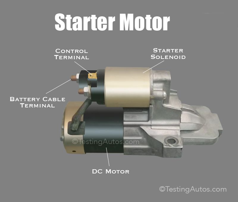
3. Touch the free end of the negative jumper cable against the negative terminal of the battery. You should hear the starter motor spin but the Bendix gear will not engage. If the starter motor fails to spin, it must be replaced.
Testing the Solenoid and Starter Motor Together1. Connect a negative jumper cable to the negative terminal of the battery and the body of the starter motor.
2. Connect a positive jumper cable to the positive terminal of the battery.
3. Connect the free end of the positive jumper cable to the nut on the solenoid from the starter motor that secures the wire from the battery to the starter motor.
4. Connect one end of a test lead to the positive jumper cable attached to the solenoid.
5. Touch the free end of the test lead to the spade terminal on the solenoid. The starter motor should spin and the solenoid should force the Bendix gear out of the starter motor.
Testing a Bendix Gear Starter with Separate SolenoidThe starter has a single wire connecting to it from the solenoid.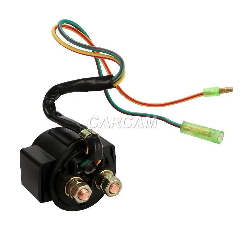 The solenoid has two terminals at one end, and a pair of wires leading out from the other end. The starter motor features a Bendix gear.
1. Connect a negative jumper cable to the negative terminal of the battery, and the other end to the body of the starter motor.
2. Connect a positive jumper cable to the positive terminal of the battery.
3. Touch the free end of the positive jumper cable to the positive wire coming from the starter. The starter motor should spin and the Bendix gear should be forced out of the starter. If it doesn’t, the starter motor is faulty and must be replaced.
Testing Only the Solenoid1. Connect a negative test lead to the negative wire coming from the solenoid, and a positive test lead to the positive wire coming from the solenoid.
2. Connect a positive jumper cable to the positive test lead, and the other end to the positive terminal of the battery.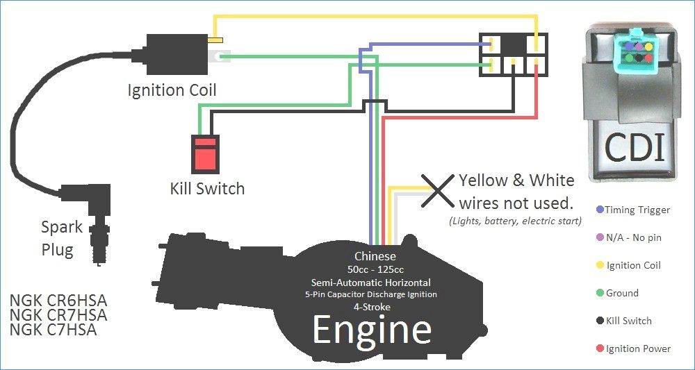
3. Connect a negative jumper cable to the negative test lead.
4. Touch the free end of the negative jumper cable to the negative battery terminal. The solenoid should make a clicking sound, indicating that it's working.
5. Connect a multimeter to the two terminals on the solenoid.
6. Set the multimeter to resistance. The multimeter should show an open circuit.
7. Touch the free end of the negative jumper cable to the negative battery terminal. The multimeter should show an open circuit, proving the solenoid is working. If the solenoid makes no sound and doesn’t make a closed circuit, it’s faulty and must be replaced.
Testing a Starter with Separate SolenoidThe starter has a single wire connecting to it from the solenoid. The solenoid has two terminals at one end and a pair of wires leading out from the other end. There is no Bendix gear, but there’s a splined shaft coming from the starter motor.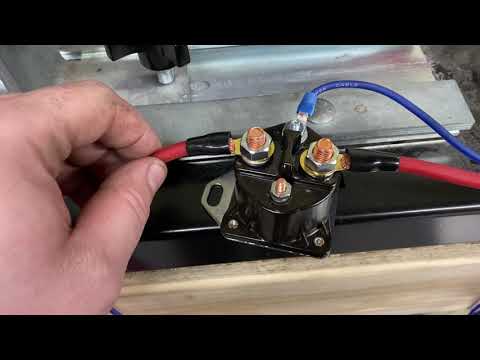
1. Connect a positive jumper cable to the positive terminal of the battery, and the other end to the nut on the starter motor that secures the positive wire from the solenoid.
2. Connect a negative jumper cable to the negative terminal of the battery.
3. Touch the free end of the negative jumper cable to the negative battery terminal. The starter motor should spin. If the starter motor fails to spin, it’s faulty and must be replaced.
Testing Only the Solenoid1 -7. Repeat the steps for testing only the solenoid, as outlined in the previous section.
body
11/22/2017 #Relay retractor # Starter
Retractor relay: starter control Electric car starter is controlled by a special device located on its body - a retractor (or traction) relay.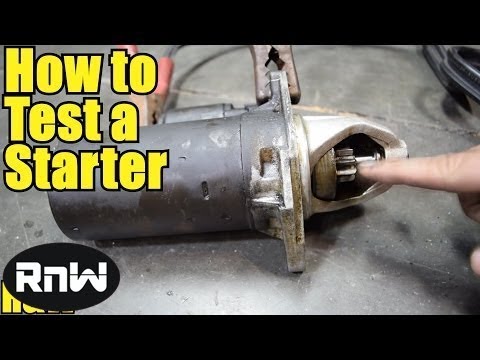 All about solenoid relays, their design, types and principle of operation, as well as the correct selection and replacement of the relay in the event of a breakdown - read in this article. nine0003
Starter solenoid relay (traction relay) - automotive electric starter assembly; a solenoid combined with a contact group that connects the starter motor to the battery and mechanically connects the starter to the flywheel crown when starting the engine.
The solenoid relay is included in the mechanical and electrical parts of the starter, controlling their joint work. This node has several functions:
The traction relay, although it works as part of the starter, is a separate unit that plays an important role in the operation of the engine starting system.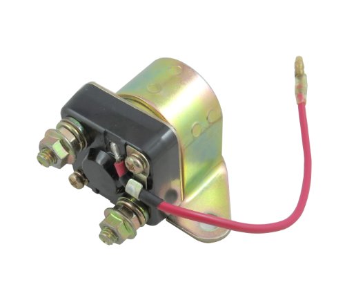 Any malfunction of this unit will make starting the engine much more difficult or impossible, so repair or replacement must be carried out as soon as possible. But before buying a new relay, you should understand its types, features and principle of operation. nine0003
Starter solenoid assembly
Electric starters currently use identical solenoid relays in design and operation. This assembly contains two interconnected devices - a power relay and a solenoid with a movable armature that turns it on (and at the same time brings the bendix to the flywheel).
The design is based on a cylindrical solenoid with two windings - a large retractor and a retainer wound on top of it. On the back of the solenoid is a relay housing made of a durable dielectric material. On the end wall of the relay there are contact bolts - these are high-section terminals through which the starter is connected to the battery.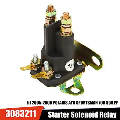 The bolts can be steel, copper or brass, the use of such contacts is due to high currents in the starter circuit when starting the engine - they reach 400-800 A or more, and simple terminals would simply melt at such a current. nine0003
Inside the solenoid is a movable rod, which on the relay side carries a contact disk - a circle of brass or other alloy. The rod is withdrawn from the contact bolts by a spring, therefore, in the non-working position, the circuit is open. Also, a massive anchor is located inside the solenoid, however, this part does not have a rigid fixation and, if necessary, can be easily removed. The armature is a metal (steel) rod of circular cross section, it is spring-loaded and protrudes from the solenoid in the non-working position. At the rear end of the armature there is a recess for resting against the relay rod. On the outer part of the anchor, a groove, hole, brackets or other devices are made for connection with the starter drive plug. nine0003
This whole structure is placed in a metal case (separable or non-separable), on the dielectric case of the relay there are terminals for connecting the assembly to the appropriate electrical circuits - the power circuit, the ignition switch circuit and, if provided, to the ignition coil circuit. The relay is rigidly mounted on the starter housing.
Traction relays, having a fundamentally identical design, are divided into two types according to their functionality (and the number of contacts on the relay side):
The first type of relay has the construction described above, while the second type relay has an additional terminal with a spring contact, which is closed by a contact disk. In the relay of the first type there are only four terminals - two power and two low-current (for connecting the retracting and holding windings), and in the relay of the second type there are already five terminals - two power, two low-current and one additional. nine0003
Connection diagram for solenoid relay with auxiliary contact and auxiliary starter relay
Solenoid relays of all types have the same principle of operation.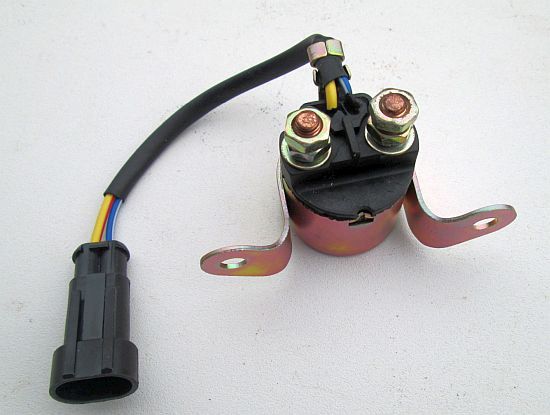 There are three processes running in parallel at this node.
When the ignition key is turned to the starter position, current from the battery is supplied to both coils of the solenoid - retracting and holding. A magnetic field arises in the solenoid, which draws in the armature - it overcomes the resistance of the spring and enters the inside of the solenoid until it stops. Moving, the armature pulls the fork, which, acting as a lever, brings the starter drive with the drive gear fixed to it to the flywheel ring gear - the starter is mechanically connected to the engine. nine0003
Also during movement, the anchor pushes the rod with its back side. The contact disk fixed on the rod rests against the contact bolts and closes the starter power supply circuit - the starter armature starts to rotate, the torque from it through the bendix goes to the flywheel and crankshaft, the engine starts. If the relay has an auxiliary contact, then when it is closed, current is supplied to the ignition coil or any auxiliary equipment necessary to start the engine.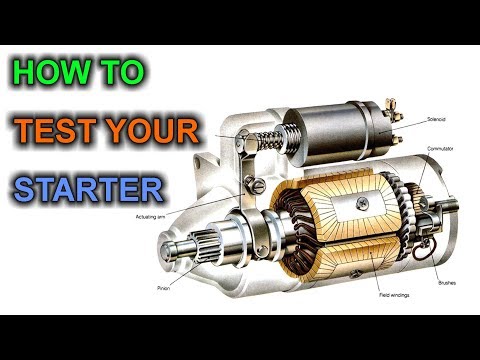 nine0003
When the contact bolts are closed, the retracting winding is short-circuited (its terminals are closed to each other), so it stops working. However, the holding winding is still connected to the battery, and the magnetic field it creates is sufficient to hold the armature securely inside the solenoid.
After a successful start of the engine, the ignition key returns to its original position, as a result of which the holding winding circuit breaks - in this magnetic field around the solenoid disappears and the armature is pushed out of the solenoid by the action of the spring, and the rod is retracted from the contact bolts. The starter drive is retracted from the flywheel crown, and the starter is disengaged. The traction relay and the entire starter are transferred to the position of readiness for a new engine start. nine0003
The general arrangement of the electric starter and the location of the solenoid relay in it
The traction relay is subjected to significant electrical and mechanical stress, so there is a high probability of its failure even with careful operation.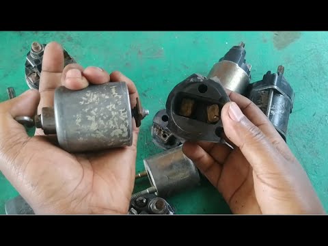 Various signs indicate a malfunction of this unit - the absence of a characteristic knock of the starter drive supply when the ignition is turned on, weak rotation of the starter with a charged battery, starter "silence" when the drive supply is running, and others. Also, malfunctions are detected when the relay rings - usually there are breaks in the windings, an increase in resistance in the power circuit due to burning and contamination of the contacts, etc. Diagnostic algorithms, usually given in the vehicle manual, help determine the malfunction. Often, it is difficult or impossible to eliminate the identified problems (for example, a break in the retracting or holding windings, breakage of the contact bolt, and some others), so the relay is easier and cheaper to completely replace. nine0003
Only those types and models of solenoid relays specified by the vehicle manufacturer should be selected for replacement. The purchase must be made by catalog numbers - this is the only way you can confidently change the unit and make the starter work in normal mode.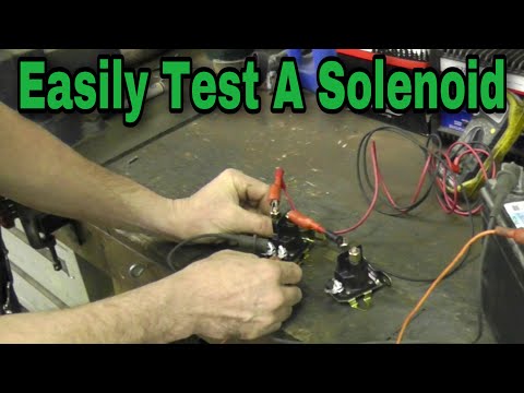 It is difficult or impossible in principle to install a relay of another type (due to unequal dimensions), and if this can be done, then the starter may not work correctly or not perform its main function at all.
To replace the relay, the electric starter must be removed from the engine and disassembled, often with a special tool. When installing a new relay, it is necessary to carefully make electrical connections - the wires are pre-stripped and twisted, when fixing them on the terminals, it is necessary to ensure reliability by preventing sparking and heating. All operations are best performed in accordance with the recommendations prescribed by the automaker in the instructions for the repair and maintenance of the vehicle. nine0003
In the future, the traction relay, like the starter itself, requires only periodic inspection and testing in accordance with the maintenance regulations. When properly selected and replaced, this assembly will operate reliably and efficiently, providing reliable engine starting.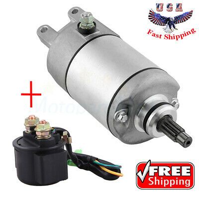
#Generator bar
Generator bar: fixing and adjusting the car's generator
14.09.2022 | Articles about spare parts
In automobiles, tractors, buses and other equipment, electric generators are mounted to the engine by means of a bracket and a tensioner that provides belt tension adjustment. About the generator strips, their existing types and designs, as well as the selection and replacement of these parts - read the article. nine0003
#Compressor adapter
Compressor adapter: reliable pneumatic connections
08/31/2022 | Articles on spare parts
Even a simple pneumatic system contains several connecting parts - fittings, or adapters for the compressor. About what an adapter for a compressor is, what types it is, why it is necessary and how it works, as well as the correct selection of fittings for a particular system - read the article.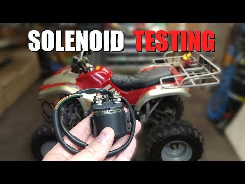
#Nissan stabilizer link
Stabilizer bar Nissan: the basis of the lateral stability of the "Japanese"
06/22/2022 | Spare Parts Articles
The chassis of many Japanese Nissan vehicles is equipped with a split type anti-roll bar connected to the suspension parts by two separate struts (rods). All about Nissan stabilizer struts, their types and design, as well as selection and repair - read in this article.
#Drive V-belt
Drive V-belt: reliable drive of aggregates and equipment
06/15/2022 | Articles about spare parts
Gears based on rubber V-belts are widely used to drive engine units and in transmissions of various equipment. All about drive V-belts, their existing types, design features and characteristics, as well as the correct choice and replacement of belts - read the article.
Back to the list of articles
 / MotoDoctor Repair of ATVs, UTVs and snowmobiles. nine0001
 Posted by by MotoDoctor
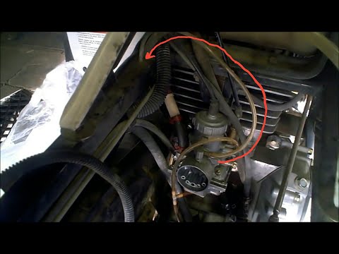
One of the problems with starting the engine on an ATV is found in the electrical system. To start the engine, we need to turn on the ignition and press the "Start" button (if the ATV is in gear, you need to additionally press the brake pedal). All ATV owners are familiar with this startup process. But here is the problem itself, after the actions performed, your ATV does not even make any sounds. Of course, first of all, we check whether the battery is holding a charge. If the battery is good, we proceed to check the wiring connections. Sometimes at the factory, when installing electrical equipment, the connecting chips are turned on, but not fixed with a lock. So sometimes, due to unscrupulous assemblers, these chips are disconnected and the contact naturally disappears. It is not very difficult to identify such a malfunction; it is enough to inspect the entire electrical wiring circuit and determine where there is no reliable connection. True, for this it is often necessary to dismantle plastic elements, so that there would be access to all electrical equipment connections. If it's plastic on a Chinese ATV, be extra careful as he is very fragile. nine0003
 In some ATV circuits, the starter relay constantly receives (-) and (+) is supplied when the (start) button is pressed, and in others, vice versa, you can determine all this with the help of instruments. For example, you have determined that the power is not going to the relay, then we recommend that you check the start button for serviceability. But as we said, the first thing to check is all electrical wiring connections. And now let's consider the option if power comes to the starter power relay and the relay itself works but the electric starter is silent, then here it seems to be faulty. In this case, you need to unscrew the mounting bolts and remove the starter from the ATV launcher. In this state, turn on the button (start), if the electric starter does not start working, then the malfunction is in it. In this article, we examined the problem of an electric start malfunction on an ATV, which is directly related to the operation of electrical equipment, but in some cases the engine cannot be started from an electric starter due to a malfunction of the mechanical start system, this is the so-called electric starter overrunning clutch.