by Jezreel
When you want to control a winch, one typically uses a remote. A remote comes with the winch kit when the winch was first bought. But what if you don’t want a remote? You find it hassle to keep plugging the remote then unplugging it every time you use the winch. What if you want to use a winch without getting off your car, and just use it from inside your vehicle? This is where a winch rocker switch can help.
A winch rocker switch is a rig that utilizes a switch to control the winch instead of a remote. You can have it installed in the driver’s seat, giving you control over the winch while at the same time using the car. This also removes the hassle of plugging and unplugging the remote when using them winch every time. You only need to flip the switch in your driver’s seat to control the winch.
But how do you exactly have it installed? Hiring someone to do it for you can get expensive, so it’s best for you to do it yourself. If you think you it’s hard, worry not, with our guide, you can have the switch installed easily.
At a Glance
Here is the tutorial with how to install the winch rocker switch, this can get complicated so follow the instructions carefully. Take note
that you are going to handle electrical wirings so please proceed with caution.
Before Installation
Installing The Rocker Switch
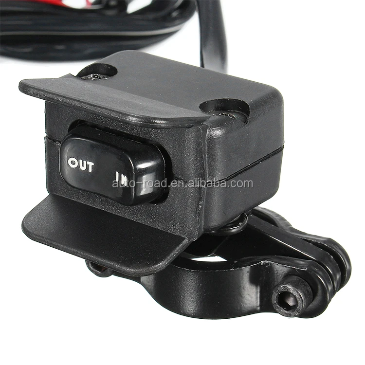
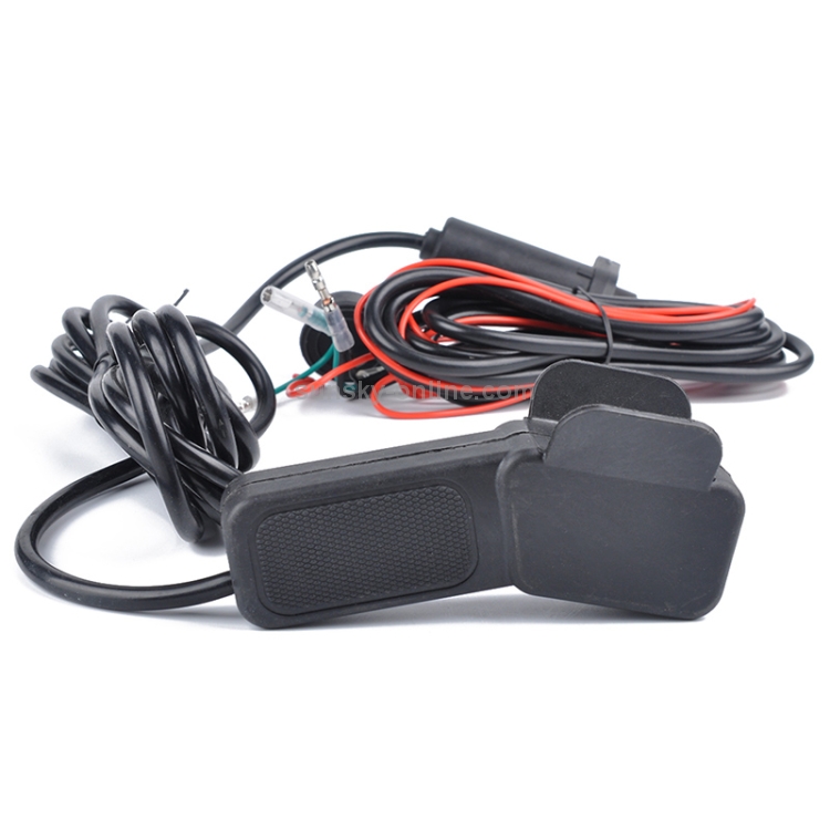 Repeat for the green and red wires.
Finishing Installation
Note: The winch rocker switch you bought might have a different variation depending on which model you bought please refer to that.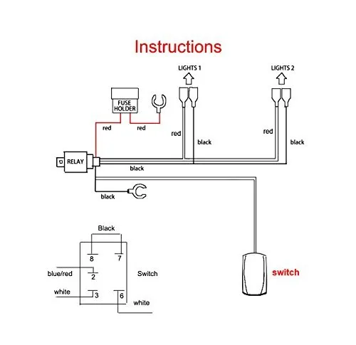
If you are looking for a lightweight winch for lightweight work and does not cost much, consider a 2500 lb winch. The 2500 lb winch may seem tiny compared to the huge 12000lb winches. It still is a winch though, and can still do its job, albeit lighter utility work and at a cheap cost too.
Here are some of our 2500 lb winch recommendations.
Now that you have learned how beneficial a winch rocker switch is and how to install it, what do you think? Share your thoughts below. Our website offers other tips and guides as well such as Best Winch Under $500, Best Pickup Truck Cranes, and Best Rambox Tonneau Cover.
We are dedicated to providing our customers with custom solutions. Feel free to contact us with any questions.
Home / Extras / KFI Winch Switch Kit | Replacement UTV & ATV Winch Switch
KFI UTV Dash Rocker Switch KIT
Kit Includes:
Specifications:
 This mean two contact points instead of just one for better repeatability operation.
KFI Mini-Rocker Handlebar Switch
Kit Includes:
Specifications:
SHARE:
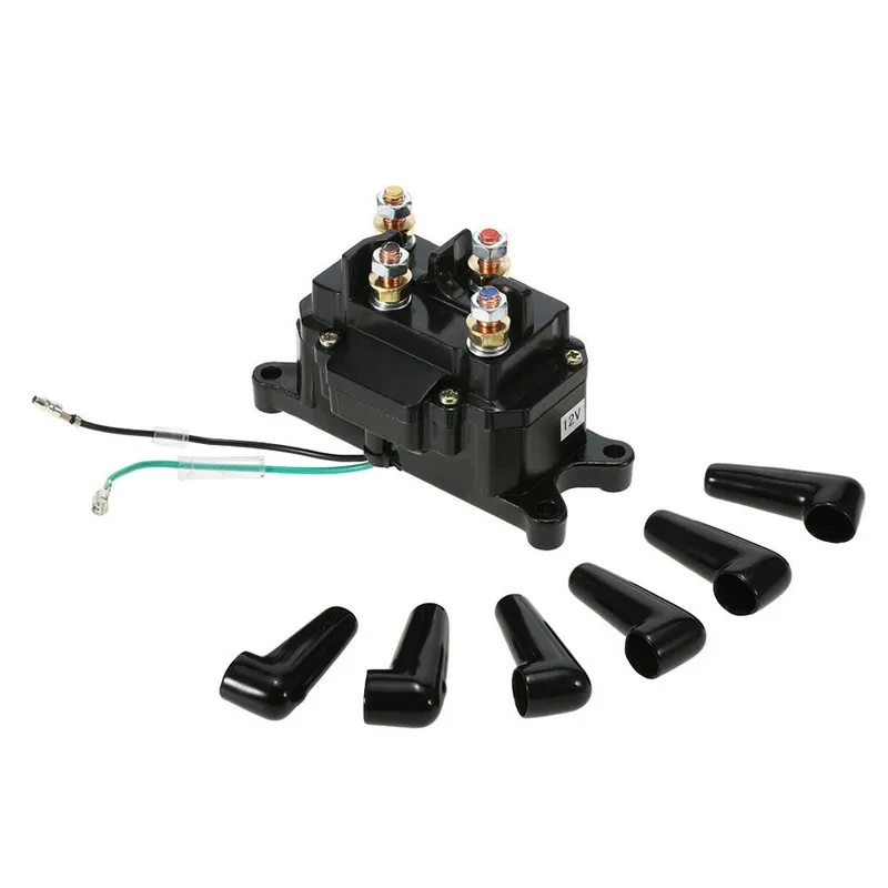
Champion 3500 pounds (1588 kg) Guide of the winch user
9000
ChampionPowerequipment. com
com
Congratulations on your purchase of Champ's ion Power Equipment (CPE) product. CPE designs, manufactures and supports all of our products to strict specifications and guidelines. With proper product knowledge, safe use and regular maintenance, this product should last for many years.
At the time of publication, every effort has been made to ensure the accuracy and completeness of the information in this manual, and we reserve the right to modify, modify and/or improve the product and this document at any time without notice.
CPE values the design, manufacture, operation and maintenance of our products and the safety of the operator and those around the winch. Therefore, IMPORTANTview carefully read this product manual and other product materials, and thoroughly familiarize yourself with the assembly, operation, hazards, and maintenance of the product before use. Fully familiarize yourself and ensure that others who plan to work with the product are also fully familiar with the proper safety and operating procedures before each use. Please always use common sense and always use caution when operating the product to avoid accidents, property damage or personal injury. We want you to keep using your CPE product and enjoy it for years to come.
When contacting CPE for parts and/or service, you will be asked to provide the full model and serial numbers of your product. Rewrite the information contained on the passport plate of your product in the table below
Technical Support command CPE
1-877-338-0999
100722
Safety symbols are designed to draw your attention to possible hazards. Safety signs and their explanations deserve your careful attention and understanding. Safety warnings by themselves do not eliminate any danger. The instructions or warnings contained therein are not a substitute for proper accident prevention measures.
DANGER!
DANGER indicates a hazardous situation which, if not avoided, will result in death or serious injury.
WARNING
WARNING indicates a hazardous situation which, if not avoided, could result in death or serious injury.
ATTENTION!
WARNING indicates a hazardous situation which, if not avoided, may result in minor or moderate injury.
WARNING
WARNING indicates information that is considered important but not hazard-related (eg property damage notices).
WARNING
Cancer and Reproductive Harm www.P65Warnings.ca.gov
WARNING
Do not use as an overhead lift. Do not use this winch to lift or move people or animals. Never step over the cable/rope when working under load. Always keep a safe distance to the opposite side of the cable/rope when working under load.
WARNING
Never exceed the power rating. Be aware that the cable/cable may break before the engine has stopped. For heavy loads at or near rated capacity, always use a breakaway block to reduce strain on the cable/rope.
WARNING
Do not use the winch to secure or hold a vehicle for an extended period of time. Always install lock blocks on the wheels of the vehicle when it is on a slope. Do not use the winch to secure the vehicle for transport purposes. Never move the vehicle to tow a load (towing) while using a cable/winch cable. Never release the freewheel when the winch is under load.
WARNING
Disconnect the remote control and battery cables when not in use.
WARNING
Avoid "shock loads" by periodically using the control switch to take up cable/rope slack.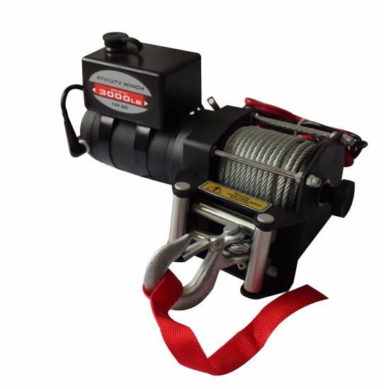 "Impact loads" may exceed the rope/cable and drum rated capacity.
ATTENTION!
Use the winch hook strap when operating the hook to wind or unwind wireline/rope.
ATTENTION!
Always wear gloves to protect your hands when handling cable/rope. Never let the cable/rope slip through your hands.
WARNING
When rewinding the cable/cable, make sure it winds up into the wind and that the cable/cable enters the drum from below, not from above. For proper rewinding, and with gloves on, lightly load the cable/cable by pressing the remote control button to pull the cable/cable. Approach the winch without letting the cable slip out of your hands. Do not allow your hands to come within 12 cm of the winch while rewinding. Turn off the winch and repeat the procedure until a few feet of cable/rope remain. Disconnect the remote control and complete winding by turning the drum by hand with the clutch disengaged.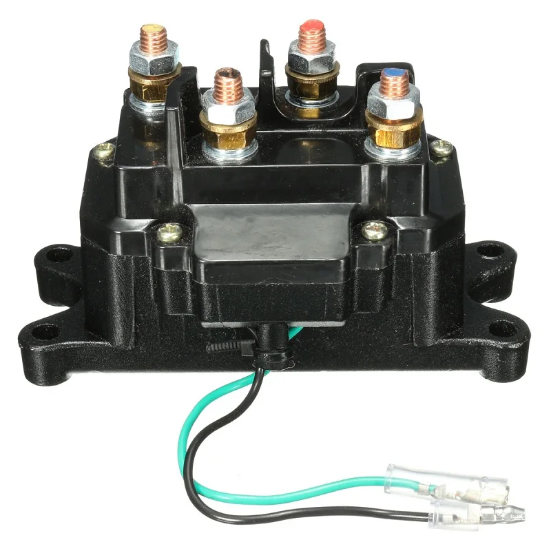 Keep your hands away from the hawse and drum when the winch is energized.
ATTENTION!
Do not wind the cable/rope around any object or catch it on yourself.
ATTENTION!
The lifting time of the winch should be as short as possible. If the engine becomes excessively hot to the touch, stop the winch immediately and let it cool down for a few minutes. Do not pull for more than one minute at or near rated load.
ATTENTION!
If the engine stalls, do not apply power to the winch. Electric winches are designed and built for intermittent use and should not be used permanently.
Some of the following symbols may be used on this product. Please study them and find out their meaning. Correct interpretation of these symbols will enable you to operate the product more safely.
Read this operator's manual before using the winch.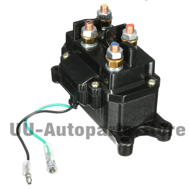 Familiarize yourself with the location and function of the controls and features. Please keep this manual for future reference.
 Engaging the clutch (“In”) locks the winch in the gear system.
  Synthetic rope is fed to the drum in the downwind position through an aluminum cable and twisted at the end to receive the yoke pin.
 Assembly Parts
This 3,500 lb (1,588 kg) CPE winch is designed for this class of standard winch bolt pattern. There are many winch mounting kits available for most popular trucks, SUVs and ATVs that use this set of bolts. If you cannot find the kit locally, contact CPE and we will provide you with a dealer name.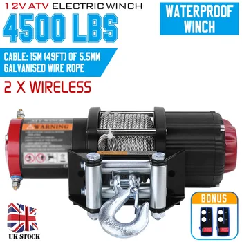
ATTENTION!
See Supplied Parts, Parts section for torque ratings. Mounting bolts must be SAE Grade 5 or higher and torqued to 34 ft-lbs (46 Nm).
WARNING!
When using the mounting plate, make sure the three main parts (motor, drum and gear housing) are properly aligned. Proper alignment of the winch will distribute the full rated load evenly.
CAUTION
The type of vehicle to which the winch and mounting channel will be applied will determine the type of mounting kit to be used (Speed Mount™ Hitch Adapter, Standard Mounting Channel, or Custom Mount Kit).
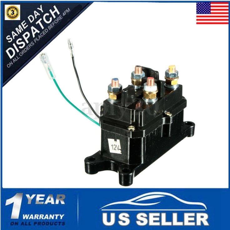
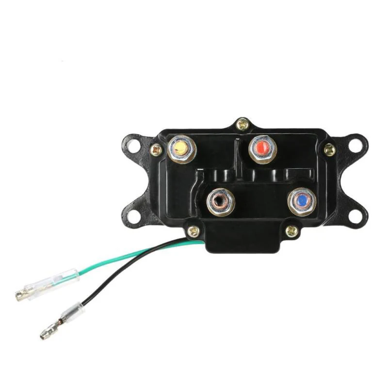
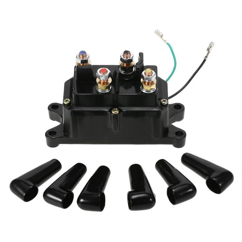
Find a location for the solenoid / contactor. It is recommended to install the solenoid/contactor near the battery in a clean and dry area. Make sure the location you choose provides sufficient clearance from all metal components. Drill mounting holes if necessary. Once a location has been found, DO NOT install the unit until all wiring has been completed (see Wiring section).
CAUTION
Contact of the terminals with metal will cause a direct short circuit, which may damage the solenoid/contactor and/or battery.
ATTENTION!
NEVER run electrical cables over sharp edges, through and/or near moving parts, or near parts that may become hot.
ATTENTION!
Battery cables must NOT be overtightened. Leave some slack for cable movement.
CAUTION
You may need to use a test light to find the correct wire.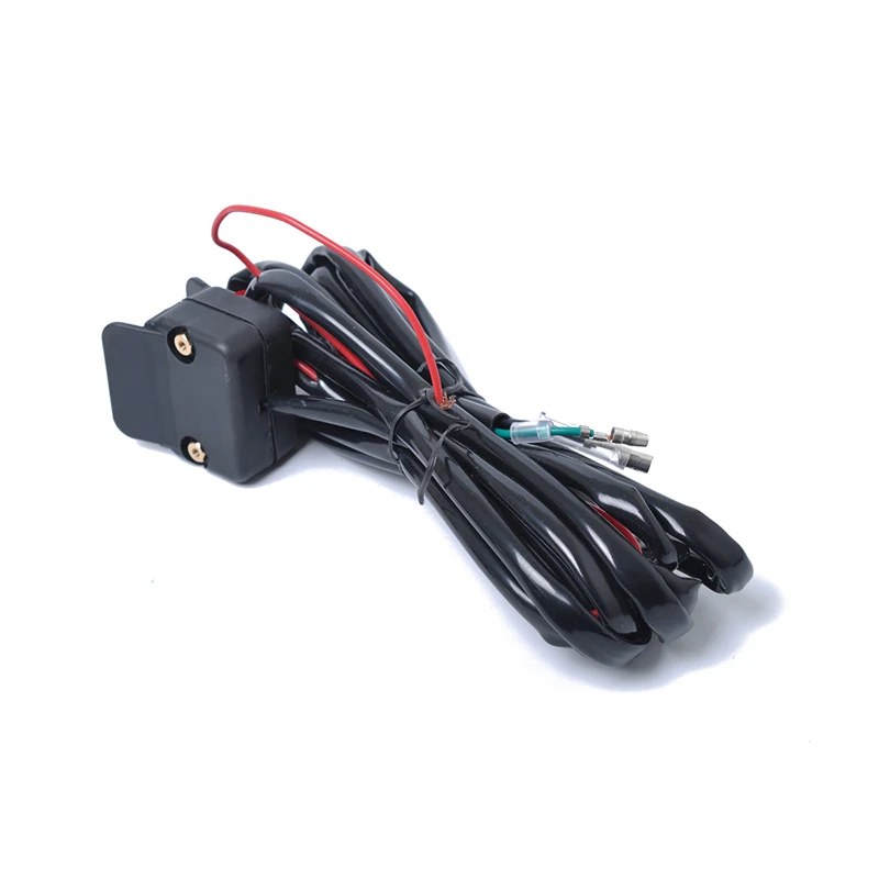 The wire should only be powered when the key is in the ON position.
WARNING
Depending on the location of the solenoid/contactor, you may need to use black and red cables instead of yellow and blue, and yellow and blue instead of red and black.
 Connect the other long red wire to the solenoid/contactor. Use the included cable ties to secure the circuit breaker assembly where convenient.
  If the drum spins and releases more cable, then your connections are accurate. If the drum spins and collects more cable, swap the wires on the motor. Repeat and check rotation.
Your Lebed 100722 is designed for a loading capacity of 3.500 pounds (1.588 kg) in the first layer (Max.) rope layer on the drum. Overloading can damage the winch, motor and/or synthetic rope. For loads over 1,750 lbs (794 kg) we recommend using a pulley block/block block to double the synthetic rope. This will help in two ways:
- reduce the number of layers of rope on the drum, and also,
- reduce the load on the rope by 50%.
When doubling the cable back to the vehicle, attach it to the towbar, frame, or other supporting part. While the winch is operating, the vehicle's engine must remain running to minimize battery drain and maximize winch power and speed.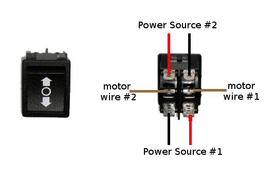 If the winch is used for a significant amount of time with the engine off, the battery may be dead and too weak to restart the engine.
Know your winch before you really need it. We recommend that you do some trial runs to get familiar with the rigging technique, the sounds your winch makes under different loads, how the rope rolls on the drum, etc.
Check synthetic rope and gear before each use. A worn or damaged cable must be replaced immediately. Use only manufacturer's identical cable with exact specifications.
Check winch installation and bolts before each operation to ensure all bolts are tight. Store the remote control in the car in a place where it will not be damaged.
Any winch that appears to be damaged, worn, or not operating normally MUST BE OUT OF SERVICE UNTIL REPAIRED. It is recommended that any necessary repairs be carried out by the manufacturer's authorized repair facility.
Only pull on areas of the vehicle specified by the vehicle manufacturer.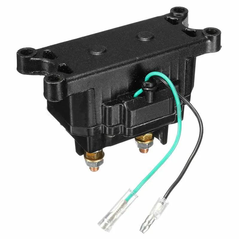 Only attachments and/or adapters supplied by the manufacturer may be used.
Find a suitable anchor such as a strong tree trunk or boulder. Always use a sling as a reference point.
Your winch is equipped with an aluminum cable that helps guide the synthetic cable and reduces snagging during short side pulls. Do not pull the winch at a sharp angle as the synthetic rope will accumulate on one side of the drum causing damage to the synthetic rope and winch.
Short jerks at an angle can be used to straighten the vehicle. Long pulls must be done with synthetic rope at a 90° angle to the winch/vehicle. When pulling a heavy load, cover the synthetic rope with a blanket or jacket five or six feet from the hook.
If the cable breaks, it will ampen snapshot back. For added protection, open the hood of your car. For pulls over 1,750 lbs (794 kg) we recommend using a wrench block/pulley block for double sling synthetic rope.
This reduces the load on the winch and the cable tension by about 50%.
Install the winch so that the uneven surface does not touch the rope. If this is not possible, an abrasive sleeve can be used to protect the rope (A).
 Release the brake pedal only when fully applied. Avoid shock loads on the winch. This may cause damage to the winch, cable and vehicle.
The owner/operator is responsible for all periodic maintenance.
WARNING
Never operate a damaged or defective winch.
WARNING
Improper service will void the warranty.
Perform all scheduled maintenance in a timely manner. Correct any problem before using the winch.
ATTENTION
For service or parts assistance, contact our customer service at 1-877-338-0999.
All moving parts of the electric winch have been factory lubricated with high temperature lithium grease. No internal lubrication is required. Periodically lubricate the cable assembly using a light penetrating oil.
It is recommended that any modifications be carried out by the manufacturer's authorized repair facility and that only parts supplied by the manufacturer be used.
Periodically rinse synthetic rope with water to remove sand, dirt, mud, or debris that may get stuck or accumulate in the rope during use. This will help prolong the life of the rope.
WARNING
Inspect rope before and after each use. If the rope wears out, it must be replaced.
Winch model. . . . . . . . . . . . . . . . . . . . . . . . . . . . . . . 100722
Rated thrust. . . . . . . . . . . . . . . . . . . . . . . 3,500 lb (1,588 kg)
Gear Ratio. . . . . . . . . . . . . . . . . . . . . . . . . 180:1
Motor. . . . . . . . . . . . . . . . . . . . . . . . . . . Permanent magnet . . . . . . . . . . . . . . . . . . . . . . . . . . . 1.2 HP (0.9 kW) (12 V DC)
Duty cycle. . . . . . . . . . . . . . . . . . . . . . . . . . . . . Intermittent
Drum size. . . . . . . . . . . . . . . . . . . . . 1.7"(D) × 3.2"(L). . . . . . . . . . . . . . . . . . . . . . . . . . [44.5 mm (L) × 81 mm (L)]
Synthetic rope. . . . . . . . . . . . . . . 3/16" (L) × 50' (D). . . . . . . . . . . . . . . . . . . . . . . . . . . . [4.8 mm (L) × 15.2 m (L)]
Total weight . . . . . . . . . . . . . . . . . . . . . . . 27.3 lb (12.4 kg)
Net weight . . . . . . . . . . . . . . . . . . . . . . . . . . 24 lb (10.9 kg)
Height . . . . . . . . . . . . . . . . . . . . . . . . . . . . . . . 5 inches (12.6 cm)
Width. . . . . . . . . . . . . . . . . . . . . . . . . . . . . . 4.8 inches (12.1 cm)
Length. . . . . . . . . . . . . . . . . . . . . . . . . . . . . 13.8 in. (35 cm)
Bolt type. . . . . . . . . 4.9" × 3" (12.4 cm × 7.6 cm)
IP rating. . . . . . . . . IP68 water and dust resistant rating
* If the motor becomes too hot to the touch, stop the winch immediately and allow it to cool for 5 minutes. Do not pull for more than one minute at or near rated load.
* * Electric winches are designed and built for intermittent use and should not be used in continuous duty applications.
Double cable and snatch pulley recommended for pulling forces over 1,750 lb (794 kg).
For further technical support:
Technical support service (free number) 1-877-338-0999 [Email is protected]
Warranty*
Chamption on Ion Power Equipment 2 years
Qualification Guarantee
To register your product for warranty and FREE Lifetime Call Center Support, visit: https://www.championpowerequipment.com/register
To complete your registration, you must attach a copy of your purchase receipt as proof of your original purchase.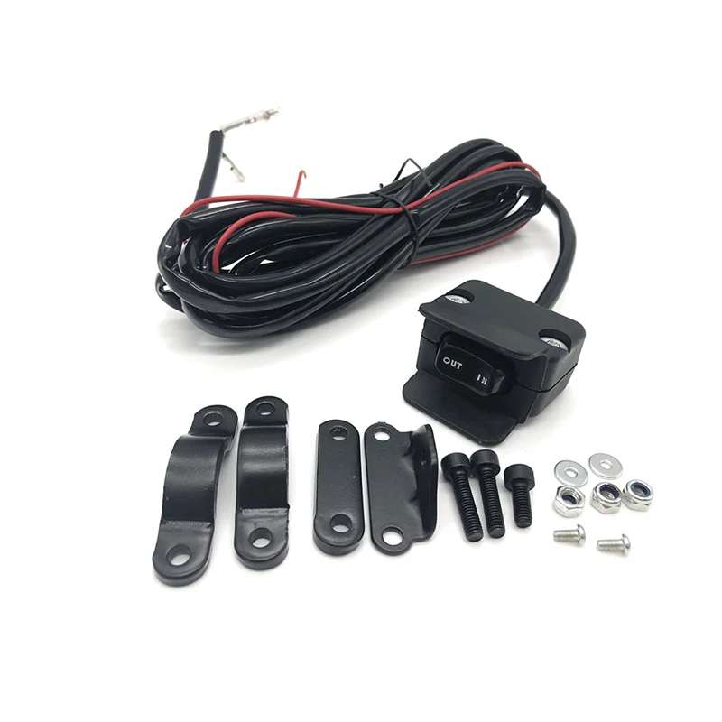 Proof of purchase is required for warranty service. Please register within ten (10) days from the date of purchase.
Repair/Replacement Warranty
CPE warrants to the original purchaser that mechanical and electrical components will be free from defects in material and workmanship for a period of two years (parts and labor) from the original date of purchase and 180 days (parts and labor) for commercial and industrial enterprises. use. Shipping costs for a product submitted for repair or replacement under this warranty shall be borne by the purchaser. This warranty extends to the original purchaser only and is not transferable.
Do not return unit to place of purchase
Contact CPE Technical Service and CPE will resolve any issue by phone or email. If the issue is not resolved by this method, CPE may, at its sole discretion, allow other repair and/or replacement methods.
Warranty exclusions
This warranty does not cover the following repairs and equipment:
Normal wear and tear
Products with mechanical and electrical components require periodic replacement and maintenance to perform well.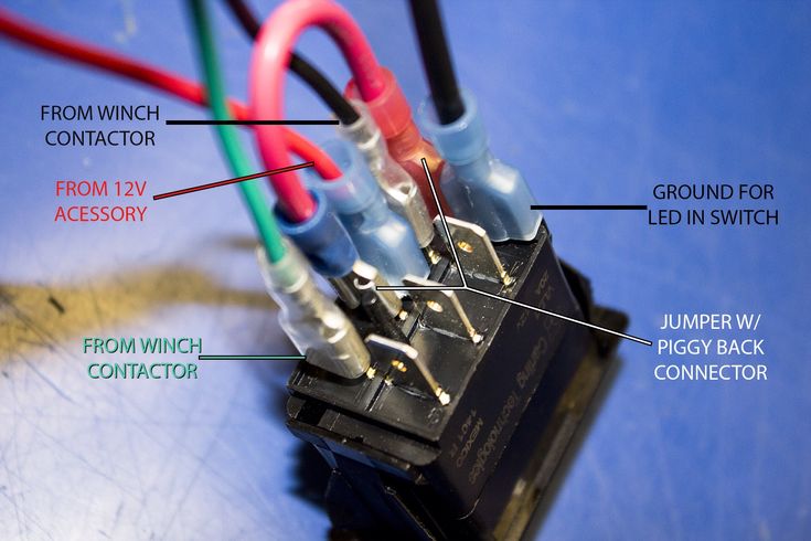 This warranty does not cover repairs if, under normal use, the life of the part or the equipment as a whole has been exhausted.
Installation, Use and Maintenance
This warranty does not cover parts and/or labor if the product is believed to have been misused, neglected, involved in an accident, abused, downloaded beyond product limitations, modified, improperly installed, or improperly connected to any electrical component. This warranty does not cover routine maintenance and is not required to be performed at the factory or by a person authorized by CPE.
Other exclusions
This warranty does not include:
- Cosmetic defects such as paint, decals, etc.
- Wear items such as winch cables, etc. storage.
- failures due to natural disasters and other force majeure circumstances beyond the control of the manufacturer.
- Problems caused by parts that are not original Champ parts of ionic energy equipment.
Limits of implied warranty and consequential damages
Champion Power Equipment disclaims any liability for loss of time, use of this product, shipping, or any incidental or consequential claim by anyone in connection with the use of this product. THIS WARRANTY IS IN LIEU OF ALL OTHER WARRANTIES, EXPRESS OR IMPLIED, INCLUDING THE WARRANTIES OF MERCHANTABILITY OR FITNESS FOR A PARTICULAR PURPOSE.
The device provided as an exchange is covered by the warranty of the original device. The replacement unit's warranty period will continue to be calculated by reference to the original unit's purchase date.
This warranty gives you specific legal rights, which may vary from state to state or province to province. Your state or province may also have other rights that are not covered by this warranty.
Contact Information
Address
Champion Power Equipment, Inc. 12039 Smith Ave. Santa Fe Springs, CA
USA
www.championpowerequipment.com
Customer Service
Toll Free: 1-877-338-0999
[e-mail protected]
Fax: 1-562-236-9429
Maintenance
Toll Free: 1-877-338-0999
[e-mail protected]
EMERGENCY SUPPORT: 6-14-2-2 204-1188
 ca.gov
 We usually use one switch to turn a chandelier or light fixture on and off. However, you can install a walk-through switch or, as it is also called, a switch in the apartment to control the lighting. The device allows you to turn on the light in one place and turn it off in another, for example, at the end of the room. It is compatible with incandescent, energy-saving and LED light bulbs and looks like a traditional switch, but its wiring is different. In this article, we will show you how to connect a single key switch to control lighting from 2 places.
The product has the same design as the usual switch, only the number of outputs for contacts is not 2, but 3: incoming and 2 outgoing.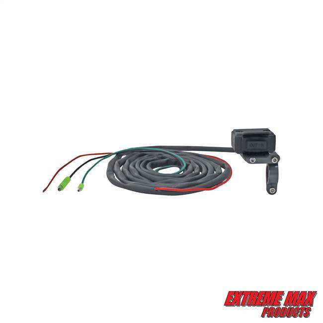 The traditional one either closes or opens the electrical circuit. And the through passage throws the circuit from one contact to another. The principle of operation is shown in the figure. The design makes it possible to turn on the light at one point, and turn it off at another.
There are also differences in appearance. As a rule, for walk-through models, 2 vertical triangles are shown on the key, looking up and down.
If the geometric shapes look to the sides, these are cross (intermediate) switches. They are needed if you want to control the lighting from 3 or more points in the house. The sequence of their connection is more complicated. We do not recommend attempting to make repairs yourself unless you are skilled in electrical wiring.
According to the observations of users, the switches save energy and increase the comfort of using lighting. They are recommended to be mounted in the following cases:
If you have a long corridor or there are darkened turns in the aisle.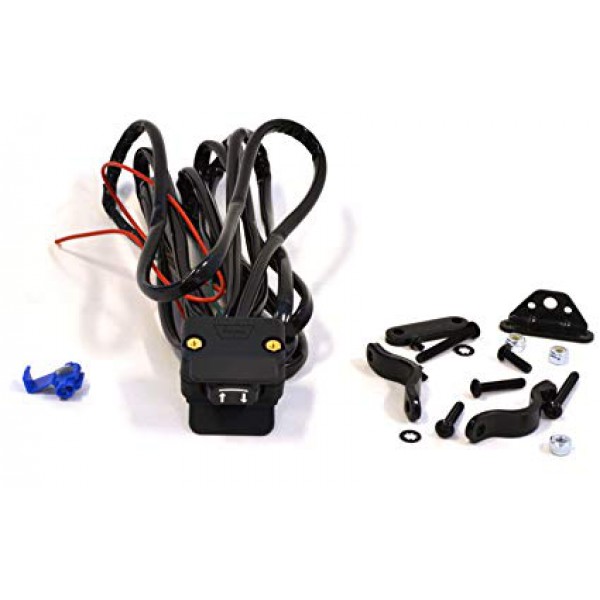
In walk-through rooms, when it is inconvenient to return to turn off the light.
In large bedrooms, when you have to get out of bed before going to bed to hit the switch.
On flights of stairs in multi-storey cottages.
Some believe that in all these cases, you can use the time relay. But people move at different speeds, and the time period may not be enough, or the light will burn in vain. The effectiveness of the switch is obvious.
Before starting the repair, pay attention to 3 important points:
A three-wire wire is used to mount the switch.
Buy 2 limit switches from the same company in the store so that their designs do not differ and they are easy to mount.
It is impossible to connect ordinary switches according to the proposed scheme.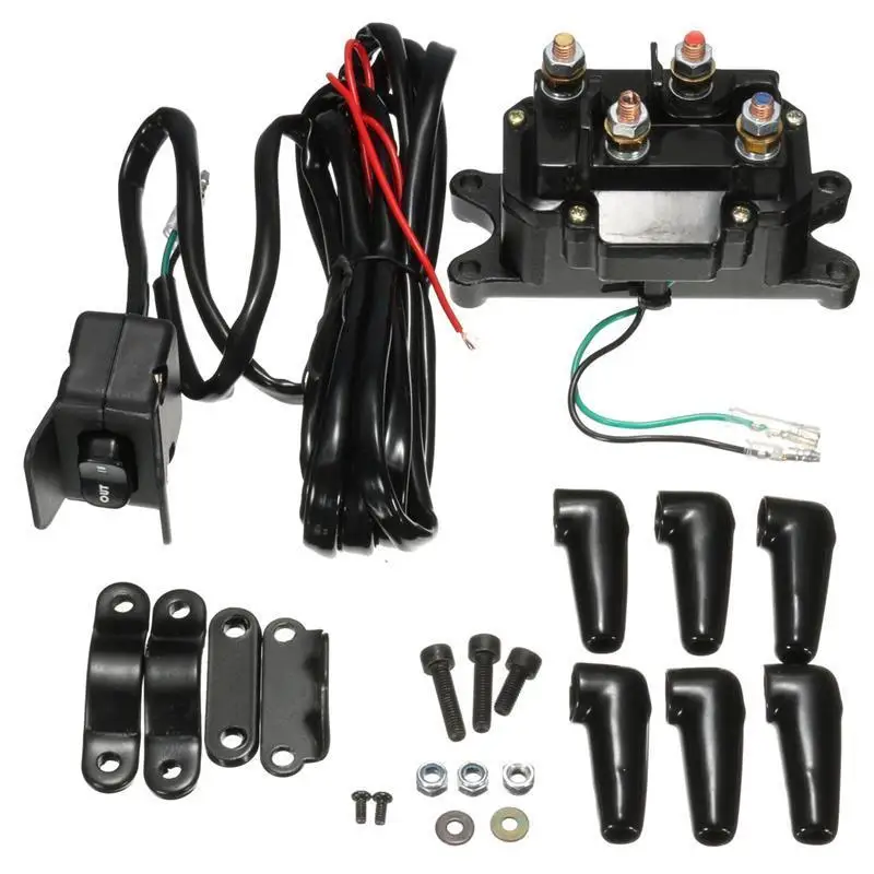 Even two-key models, which also have 3 terminals on the rear panel, are not suitable.
Next, we will describe the sequence of actions, first when installing the switch in the socket, then when connecting the cables in the junction box. All work is carried out in the absence of voltage in the network.
The most important thing at this stage is to find a common contact terminal that will transmit current from the electrical panel. As a rule, a diagram of where which terminal is located is drawn on the back of the switch. If you have an inexpensive model or you do not understand such schematic instructions, use an indicator screwdriver. After finding the desired clamp, connect the phase wire to it. Install the remaining wires in other terminals. Their position doesn't matter. Fix the structure in the socket. The second switch is mounted in the same way, only the phase cable is pulled to the chandelier.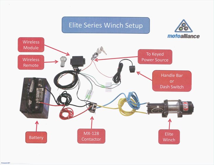
4 cables are brought into the junction or junction box: from the switchboard machine, from the switches (for convenience, we denote them No. 1 and No. 2) and from the lamp. Now you need to connect the wires in pairs correctly. Use the smallest double WAGO terminals for connection.
The wiring diagram for lighting control from 2 different points is shown in the figure. It is of a general nature, then we will describe the sequence of your actions in more detail.
For clarity, the insulation of all wires is a different color. Most common markings
White or gray - phase - a core through which the current moves to the lamp.
Blue - zero - wire with reverse current flow.
Yellow-green - grounding. "Earth" is not involved in the supply of electricity, but prevents shock if one of the circuit elements fails.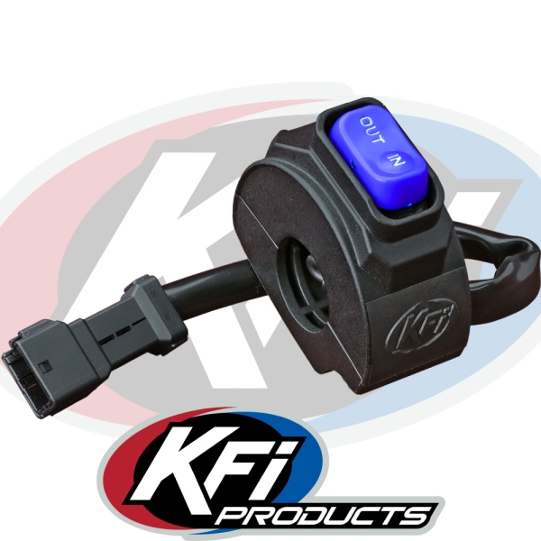
Now connect the wires in series:
Zero cable from the automatic box - with a zero channel extending from the lamp.
Connect ground wires.
Clamp the phase from the switchboard with the phase of the wire from the common terminal of switch No. 1.
The phase of the cable from the lighting fixture is from the common core of switch No. 2.
There are outgoing wires from the switches. They can be interconnected arbitrarily, but try to keep the color layout so that in the future no one gets confused in case of repair.
It remains to check the correct connection. Apply voltage and check the operation of the devices.
We have described the connection diagram of a single-key sample. The principle of connecting two- and three-key is similar. The models have 2 or 3 inputs and 4 or 6 outputs respectively. The main thing during installation is not to get confused in the wires and terminals.
Let's list the typical mistakes that people make when they first encounter the installation of walk-through switches.
Some believe that when installing the product in a socket, the common terminal is the one that is located separately. But different manufacturers have different device designs, so there is no single rule where the phase cable should go.
There are cases when the switch is connected in series with a conventional switch. To solve the problem, it is enough to correctly swap the phases.
Switches have disadvantages that are important to be aware of if you decide whether to install them or not.
The absence of a fixed position of the key, by which you can find out whether the light is on or not. In conventional designs, there is a standard key placement that indicates that no current is being applied.