Recipient Email Address
Press "Enter/Return" or "Space" key to validate your email. Only valid emails can be added. You can share with multiple people.
Subject
Message
Optional
Send a copy to sender's email address
This article tells how Salvadori – the renowned provider of tire recycling solutions and recycling technologies – helped American OTR tire manufacturer efficiently recycle their end-of-life products.
Off The Road (OTR) tires usually pose a huge challenge for companies when it comes to their recycling – OTR tires up to 51 inches in diameter previously were not easily downsized. The question was, how to take advantage by turning waste into something of value.
PreviousNext
Salvadori's equipment supplied to Inland Industrial Tire. Photos by Salvadori.
Inland Industrial Tire is a 3rd generation Off The Road (OTR) tire business in America.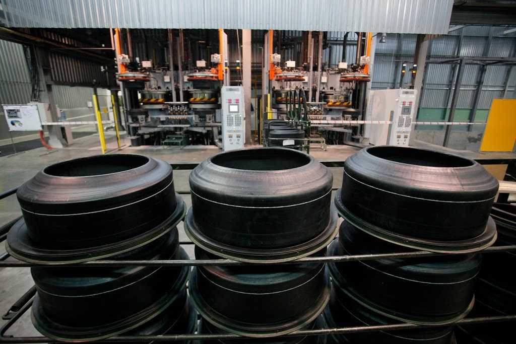 Inland sells and services OTR tires from four northern California locations. Inland CEO Eric Griffin has a dynamic vision to bring Inland’s services full circle. His vision is to recycle, repurpose and reuse those tires that Inland sells and services, and to position Inland as a major player in the new “Circular Economy”.
According to Griffin, what is occurring with scrap [OTR] tires is not sustainable.
“We want to be on the leading edge of the Circular Economy by providing a solution that downsizes and recycles these tires into new useful products. We are on an aggressive growth trajectory to double our business over the next 10 years and candidly, it’s just the right thing to do!” – Griffin said.
Given the challenges end-of-life OTR tires pose to recyclers, the company was looking for a reliable technology supplier to provide an innovative know-how.
To overcome the challenge, Inland was introduced to Salvadori by a representative from sister company TECH, as they had been using TECH’s tire & wheel service products for years. Inland CEO Eric Griffin shared his frustration with not being able to find a solution for this OTR tire downsizing challenge.
“Once I was able to interact with the Salvadori Team and see their facility firsthand I was immediately impressed.” – Griffin says.
After the initial visit, the Salvadori Team scoped the project to design, build and install two pieces of equipment created to meet Inland’s specific challenges.
To help Inland meet it’s ambitios goal, Salvadori designed a completely customized machine named “Wolverine” capable of cutting the largest OTR tires. One important facet of Wolverine, according to Salvadori, is that it is a fully automated piece of equipment which reduces labor costs and mitigates potential workplace injury liabilities. This was particularly important to Inland.
Wolverine II in action. Video by Salvadori.
The second piece of equipment, Hercules 90 is able to quickly and efficiently extract the steel bead from large OTR tires. According to Salvadori, 97% of the rubber is removed in the debeading process which enhances the value of the reclaimed steel.
According to the CEO of Inland, Salvadori’s equipment exceeded the operator’s expectations during the factory acceptance test (FAT), which took place at Salvadori’s manufacturing facility in Rovereto, Italy.
In addition, Salvadori provides the following information about its equipment:
“We are exceptionally pleased with the entire experience, the collaborative nature which enabled us to work through challenges in order to create a world class business solution is very rewarding.” said Inland CEO Eric Griffin.
According to the equipment manufacturer, Salvadori brings over 30 years of experience in recycling products and recycling equipment with an installed customer base in 40 countries around the world.
To learn more about Salvadori Recycling, please visit the company’s official website.
Surely many of you know or have even seen how large automated objects are controlled, for example, a nuclear power plant or a plant with many technological lines: the main action often takes place in a large room, with a bunch of screens, light bulbs and consoles. This control complex is usually called the main control room - the main control panel for controlling the production facility.
Surely you were wondering how it all works in terms of hardware and software, and what data transfer protocols are used there.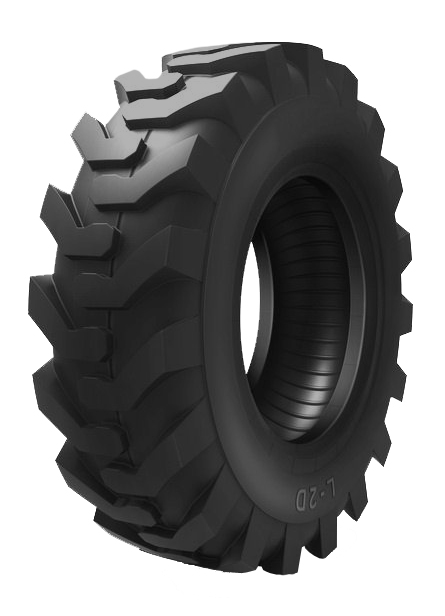 In this article, we will look at how various data gets to the main control room, how commands are given to the equipment, and what is generally needed to control a compressor station, a propane production unit, a car assembly line, or even a sewage pumping unit. nine0005
This set of words, which is not clear to the uninitiated, is used when it is necessary to describe the means of communication between control devices and subordinate equipment, for example, I / O modules or measuring devices.
By controller we mean PLC, i.e. programmable logic controllers (eng. PLC), or PKA, i.e. programmable automation controllers (eng. PAC). There are some differences between the PLC and PCA, however, they are not significant within the framework of this article, therefore, for simplicity, we will use the general term "controller". nine0003
In the Russian-speaking community of asush people, the communication channel between the controller and other devices is usually called the "field bus", because it is responsible for transmitting data that comes from the "field".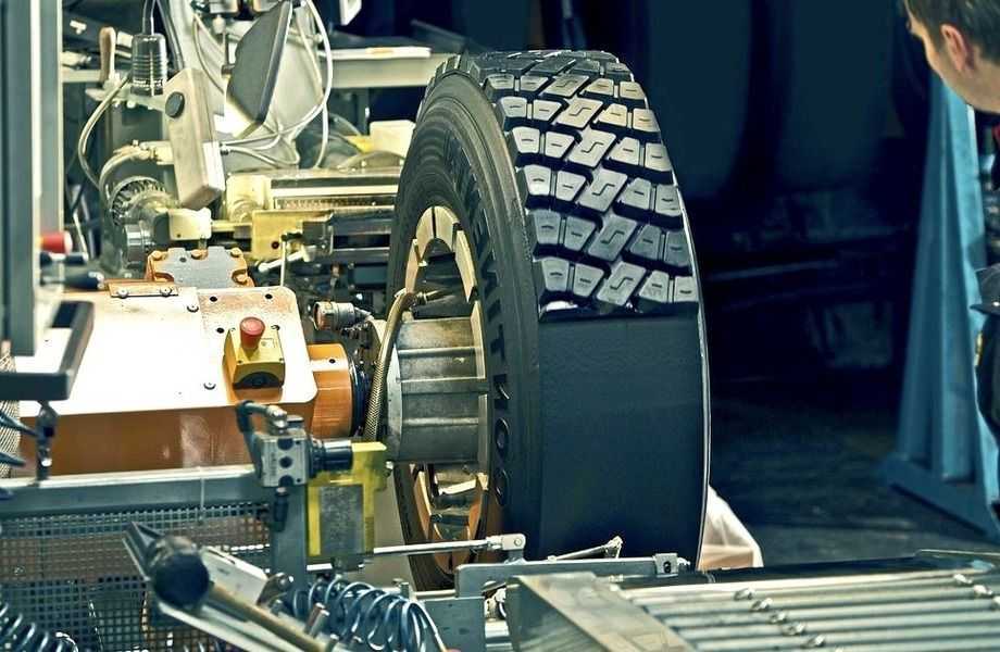
“Field” is a deep professional term that refers to the fact that some equipment (such as sensors or actuators) with which the controller interacts is somewhere far, far away, on the street, in the fields, under the cover of night. And it does not matter that the sensor can be located half a meter from the controller and measure, say, the temperature in the automation cabinet, it is still considered to be “in the field”. Most often, the signals from the sensors that come to the I / O modules still overcome distances from tens to hundreds of meters (and sometimes more), collecting information from remote sites or equipment. Actually, therefore, the exchange bus, through which the controller receives values from these same sensors, is usually called a field bus or, less often, a lower-level bus or an industrial bus. nine0003
It should be noted here that in Europe and the USA, only the devices located “in the field” are considered the field level, but not the data transmission medium. In Russian realities, the term "field bus" or "lower-level bus" is perhaps slightly vague and refers to the method of transferring data from I / O modules to the controller and vice versa.
General scheme of automation of an industrial facility
So, the electrical signal from the sensor travels a certain distance along cable lines (usually along a conventional copper cable with a certain number of cores), to which several sensors are connected. Then the signal enters the processing module (input-output module), where it is converted into a digital language understandable to the controller. Further, this signal goes directly to the controller via the field bus, where it is finally processed. Based on such signals, the logic of the controller itself is built. There is also a reverse way: from the controller, the control command via the field bus goes to the output module, where it is converted from digital to analog and goes through cable lines to actuators and various devices (not shown in the diagram above). nine0003
The top level is everything that can be touched by an ordinary mortal operator who controls the process. In the simplest case, the top level is a set of light bulbs and buttons. Light bulbs signal to the operator about some ongoing events in the system, buttons serve to give commands to the controller. Such a system is often called a "garland" or "Christmas tree" because it looks very similar (as you can see from the photo at the beginning of the article). nine0003
If the operator is more fortunate, then as the top level he will get the operator panel - a kind of flat-panel computer that somehow receives data for display from the controller and displays them on the screen. Such a panel is usually mounted on the automation cabinet itself, so you usually have to interact with it while standing, which causes inconvenience, plus the quality and size of the image - if it is a small-format panel - leaves much to be desired.
And, finally, an attraction of unprecedented generosity - a workstation (or even several duplicates), which is an ordinary personal computer. nine0003
For visual display of information on workstations and flat-panel computers, specialized software is used - SCADA systems. In human language, SCADA is translated as a supervisory control and data acquisition system. It includes many components, such as a human-machine interface that visualizes technological processes, a process control system, a parameter archiving system and event logging, an alarm management system, etc. All this gives the operator a complete picture of the processes taking place in the production, as well as the ability to manage them and quickly respond to deviations from the technological process. nine0003
Top-level equipment must interact in some way with the controller (otherwise why is it needed?). For such communication, upper-layer protocols and some kind of transmission technology, such as Ethernet or UART, are used. In the case of the Christmas tree, of course, such refinements are not needed, the bulbs are lit using ordinary physical lines, there are no sophisticated interfaces and protocols there.
In general, this upper level is less interesting than the field bus, since this upper level may not exist at all (there is nothing for the operator to watch from the series, the controller will figure out what to do and how). nine0003
Few people know, but on the seventh day of the creation of the world, God did not rest, but created Modbus. Along with the HART protocol, Modbus is perhaps the oldest industrial communication protocol, it appeared as early as 1979.
The serial interface was originally used as a transmission medium, then Modbus was implemented over TCP / IP. This is a synchronous master-slave (master-slave) protocol that uses the request-response principle. The protocol is quite heavy and slow, the exchange rate depends on the characteristics of the receiver and transmitter, but usually the score is almost hundreds of milliseconds, especially when implemented via a serial interface. nine0003
Moreover, the Modbus data transfer register is 16-bit, which immediately imposes restrictions on the transfer of real and double types. They are transmitted either in parts or with loss of accuracy. Although Modbus is still widely used in cases where a high exchange rate is not needed and the loss of transmitted data is not critical. Many manufacturers of various devices like to extend the Modbus protocol in their own unique and very original way, adding non-standard features. Therefore, this protocol has many mutations and deviations from the norm, but still successfully lives in the modern world. nine0005 The HART protocol has also been around since the 1980s, it is an industrial communication protocol over a two-wire current loop that directly connects 4-20 mA transmitters and other HART-enabled devices.
Special devices, so-called HART modems, are used for switching HART lines. There are also converters that at the output provide the user with, say, the Modbus protocol.
HART is noteworthy, perhaps, in that in addition to the analog signals of the 4-20 mA sensors, the digital signal of the protocol itself is also transmitted in the circuit, this allows you to connect the digital and analog parts in one cable line. Modern HART modems can be connected to the controller's USB port, connected via Bluetooth, or in the old way via a serial port. A decade ago, by analogy with Wi-Fi, the WirelessHART wireless standard appeared, operating in the ISM band. nine0003
The Modbus and HART protocols have been replaced by non-industrial buses such as ISA (MicroPC, PC/104) or PCI/PCIe (CompactPCI, CompactPCI Serial, StacPC), as well as VME.
The era of calculators has come, having at their disposal a universal data transfer bus, where you can connect various boards (modules) to process a certain unified signal. As a rule, in this case, the processor module (computer) is inserted into the so-called frame, which provides bus interaction with other devices. The frame, or, as true automators like to call it, the “crate”, is supplemented with the necessary I / O boards: analog, discrete, interface, etc., or all this is glued together in the form of a sandwich without a frame - one board above the other. After that, this variety on the bus (ISA, PCI, etc.) communicates with the processor module, which thus receives information from sensors and implements some kind of logic. nine0003
Controller and I/O modules in a PXI cage on a PCI bus. Source: National Instruments Corporation
Everything would be fine with these ISA, PCI (e) and VME buses, especially for those times: the exchange rate does not upset, and the system components are located in a single frame, compact and convenient, hot-swappable input boards - output may not be, but still do not really want to.
But there is a fly in the ointment, and not just one. It is rather difficult to build a distributed system in such a configuration, the exchange bus is local, you need to come up with something to exchange data with other slave or peer nodes, the same Modbus over TCP / IP or some other protocol, in general, there are not enough amenities. Well, the second thing is not very pleasant: I / O boards usually wait for some unified signal for input, and they do not have galvanic isolation with field equipment, so you need to fence a garden of various conversion modules and intermediate circuitry, which greatly complicates the element base. nine0003
Intermediate modules for signal conversion with galvanic isolation. Source: DataForth Corporation
“What about the fieldbus communication protocol?” - you ask. But nothing. It does not exist in this implementation. Through cable lines, the signal goes from the sensors to the signal converters, the converters output voltage to a discrete or analog I/O board, and the data from the board is already read through the I/O ports, by means of the OS. And no specialized protocols. nine0003
What now? To date, the classical ideology of building automated systems has changed a bit. Many factors played a role, from the fact that it should also be convenient to automate, and ending with the trend towards distributed automated systems with nodes remote from each other.
Perhaps, we can say that today there are two main concepts for building automation systems: localized and distributed automated systems. nine0003
In the case of localized systems, where data collection and control is centralized in one specific place, the concept of a certain set of I / O modules interconnected by a common fast bus, including a controller with its own exchange protocol, is in demand. In this case, as a rule, I / O modules include both a signal converter and galvanic isolation (although, of course, not always). That is, it is enough for the end user to understand what types of sensors and mechanisms will be present in the automated system, count the number of required I / O modules for different types of signals and connect them into one common line with the controller. In this case, as a rule, each manufacturer uses its favorite exchange protocol between I / O modules and the controller, and there can be a lot of options. nine0003
In the case of distributed systems, everything that has been said about localized systems is true, except for this, it is important that individual components, for example, a set of I / O modules plus an information collection and transmission device - not a very smart controller that is somewhere in booth in the field, next to the crane that shuts off the oil, could interact with the same nodes and with the main controller at a great distance with an effective exchange rate.
How do developers choose a protocol for their project? All modern exchange protocols provide a fairly high speed, so often the choice of a particular manufacturer is not determined by the exchange rate on this same industrial bus. The implementation of the protocol itself is not so important, because, from the point of view of the system developer, it will still be a black box that provides some internal structure for the exchange and is not designed for outside interference. Most often, attention is paid to practical characteristics: the performance of the calculator, the convenience of applying the manufacturer's concept to the task, the availability of the required types of input-output modules, the possibility of hot-swapping modules without breaking the bus, etc. nine0003
Popular equipment vendors offer their own implementations of industrial protocols: for example, the well-known company Siemens develops its series of Profinet and Profibus protocols, B&R develops the Powerlink protocol, Rockwell Automation develops the EtherNet/IP protocol. The domestic solution in this list of examples: the version of the FBUS protocol from the Russian company Fastwel.
There are also more universal solutions that are not tied to a specific manufacturer, such as EtherCAT and CAN. We will explore these protocols in detail later in this article and see which are best suited for specific applications: automotive, aerospace, electronics, positioning systems, and robotics. Stay in touch! nine0003
One of the most important parts of the controller is the internal bus. Although without microprocessor control devices, they had great functionality, but, however, they had a very significant drawback, namely, they did not have a bus. The reason for this was that for such control devices, each module was unique, that is, it solved some kind of its own task in automation. The connections between such modules were a complex tangle of wires. nine0003
The advent of microprocessors made it possible to greatly simplify the wiring diagram between modules and make it regular and of the same type . The reason for this simplification was the division of functions between function modules and the CPU. The most common functions remained behind the functional modules, which made it possible to significantly simplify their internal structure and unify their connection with the CPU. Common functions include receiving and transmitting signals, as well as their partial processing. Partial signal processing includes amplification, comparison, selection, filtering, galvanic isolation, analog-to-digital conversion, digital-to-analog conversion, and so on. Functional modules have become more versatile, and this versatility was greatly facilitated by the unification of input and output signals, which for all types of controllers began to have the same change ranges. The functions of complete signal processing and additional functions arising from the individual characteristics of the control and monitoring objects were assigned to the CPU and application software. The emergence of bidirectional trunk transceivers, the outputs of which have a third state, also contributed to a significant simplification of the connections between the USO modules and the CPU. Thanks to such transceivers, it was possible to turn the connection scheme between the USO and CPU modules into a full-fledged bus connecting parallel inputs and outputs of the USO and CPU modules of the same name. The original circuit design based on the parallel connection of the outputs of the USO modules according to the "mounted OR" scheme reduced the load capacity of the bus and somewhat complicated the circuit design of the input stages of the USO modules. nine0003
The internal busbar can be designed differently. If the controller has a frame structure, then the internal bus can be made in the form of a connecting printed circuit board with detachable connectors (sockets) into which USO and CPU modules are inserted. When the controller modules are distributed in a cabinet, the connection between them can be made using a ribbon cable. If the controller is made in the form of structurally complete modules installed on a DIN rail, then the bus in such a controller can be implemented using bus connectors. nine0003
First generation controllers had a non-standard internal bus. That is, each manufacturer chose his own type of plug-in connector, and distributed connecting conductors for various purposes over its contacts in the way that was more convenient for him. And although the dimensions of the printed circuit boards of the controller modules were standardized (that is, their sizes were selected from the standard range), controller modules from different manufacturers were incompatible either in the type of connectors or in the binding of signals to connector pins. nine0003
With increasing microprocessor power, controller manufacturers began to switch to a standard internal bus (second generation controllers). The shortened ISA bus was chosen as the standard. The abbreviation ISA is the name of the standard that defined the type of connector, tied the signals to the pins of this connector, and also set the levels of the transmitted signals. Thanks to this, controller modules from different manufacturers, made in the same standard, have become interchangeable. nine0003
The internal bus of microprocessor-based controllers is functionally divided into three parts: an 8-bit data bus, an address bit bus, and a control bus. However, the data bus remained eight-bit, although the processor capacity increased. This is explained by the fact that most of the time in the controllers is spent on data processing, and here the higher the processor capacity, the faster it is carried out. The CPU interrogates the USO modules according to a program-defined cycle, the duration of which for most control objects, due to their inertia, is set equal to one or two seconds. Relatively little time is spent polling the modules (of the order of several milliseconds). Switching to a sixteen-bit data bus gives a gain in time of several microseconds, which does not justify the cost of hardware. An increase in the data bus width leads to an increase in the contacts on the module connectors, and in some cases requires an additional connector, which can lead to an increase in the sizes of the controller module boards and the connection board. In addition, an increase in the width of the data bus leads to an increase in the number of elements in the modules and increases the complexity of manufacturing the product. Therefore, increasing the capacity of controllers at this stage in the development of microprocessor technology is not yet economically feasible. nine0003
11/22/22
MPECVD crystal production plant, automatic control system upgrade,...
Read more 3
