by textileblog
Sewing Thread Inspection:During sewing of garments, frequent breaking of thread, directly influences on the apparel production and its quality. It is important to mention here that in running condition of machine, the sewing threads run through the needles at a speed of 140 to 165 K.M per hour. Thread strength may be decreased from 2 to 32% due to the friction of sewing threads with the various parts of machines & fabrics. For that reason, before buying of sewing threads, the below mentioned properties of threads should be verified:
Can You Use Sewing Thread for Beadi...
Please enable JavaScript
Can You Use Sewing Thread for Beading?
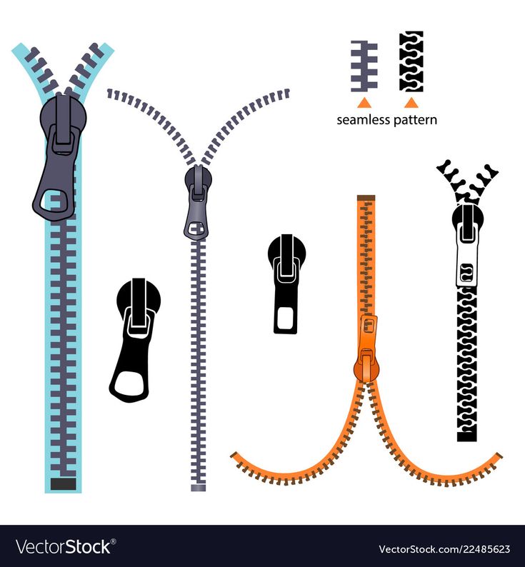
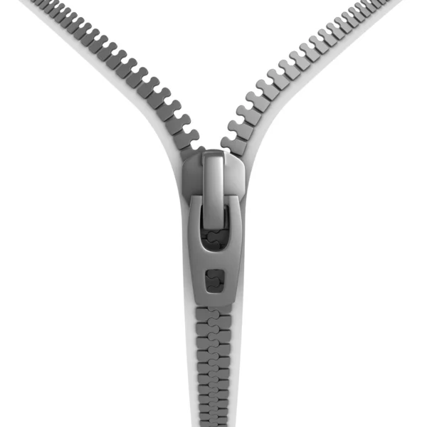
Fig: Sewing thread and zipperA. Thread Construction / Ticket Number:
The tests which should be done in order to be sure about the construction of thread, are as follows:
B. Sewability:
The sewing fitness of a thread is called its sewability. In order to determine the sewability, 3 packages of thread are taken from a lot, 100 yards of sewing is done and the running performance of the machine is listed. The main objective of this test is to know the capacity of flawless and beautiful sewing of each thread in a normal condition and at the highest speed of the sewing machine. During the test of sewability, the other properties of thread that should be examined are as follows:
1. Imperfections: If there is any knot or slub in the thread, the thread will break frequently, causing decreasing of both the efficiency and production of the machine and the quality of the produced goods will also be deteriorated.
You may also like: Sewing Thread Consumption Guide for Professional
2. Finish: The finish of thread is mainly meant to lubricant that helps thread to pass through needle eye and the various guides of machine.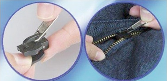 The amount of lubricant in threads may be from 3 to 15%. The amount of lubricant should be in the same percentage for each package of thread in a lot otherwise various problems will arise sewing.
3. The color of thread: Any color of thread including white, must match with its sample and the color of the thread in the same lot should not differ considerably. Otherwise, adverse effect may result on the quality of the garments.
4. The package density: Should not have any difference in density of a package or a cone from another cone. If there is difference in density, the efficiency and productivity of the machine will decrease due to frequent adjustment of the tension of the thread.
5. Winding: Thread should be properly wound in the package. Otherwise thread can break frequently during sewing due to the snarling of thread after coming out of the package. As a result, both the production and the quality of goods may be damaged.
6. Yardage: The length of thread in a package of thread has to be within 2% of the mentioned length (yardage) otherwise that package may be cancelled.
You may also like: Various Factors Influence Sewing Thread Consumption
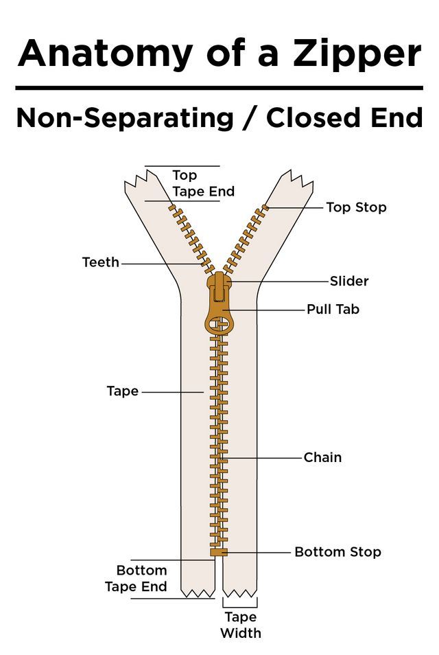
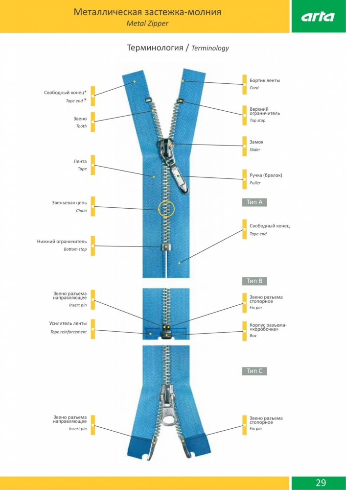
Zipper Inspection:Chain or zipper is a special part of a garment, which if defective, the garment may be unfit for wearing. Need to be ensured beforehand about the below issues so that the defects related to the zippers should not arise.
1. Dimension: Need to be ensured beforehand about the measurement of the length of the chain and the width of the tape so that it does not create any problem for shortage of dimension during attaching to the garments.
2. Stops: The stops ends at the upper end and the lower end of the chain must be stopped by sewing in garments properly, fairly and in well secured.
3. Uniform color: The color of the chain tape must be uniform.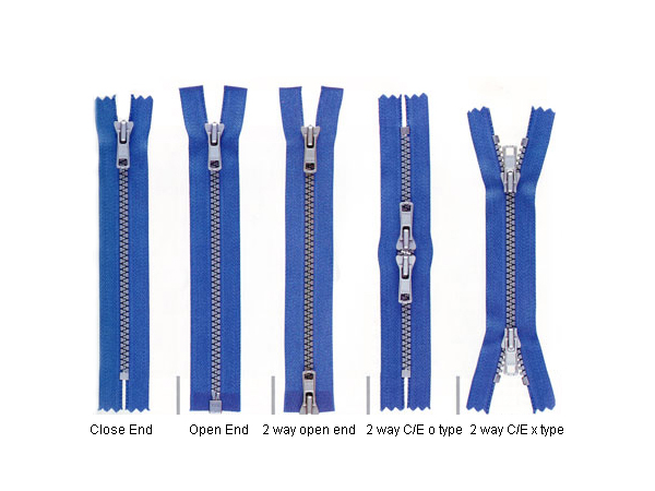
4. Puckering: Need to be ensured so that no puckering in garments happen after attaching of the chain by sewing.
5. Dimension and color: After washing or dry cleaning or ironing, the dimension of the chain or its color should not be changed.
6. Slider: The movement of the slider through the chain should be easy but care should be taken so that the slider can be well locked in the chain.
7. Arrow mark: The chain should be attached in the garment as per the arrow mark in the slider.
Share this Article!
Categories Apparel Industry6 Methods
Zippers varying in specifications and types require different strengths suitable for different purposes.
The methods of testing zipper strength are not limited, but the basic strength is usually determined by following inspection methods.
1. Flat pull strong test
The flat tensile strength is the most basic strength indicator. It is used to test the ability of the zipper teeth to resist the lateral force in the interlocked state, which is very similar to the actual state of use.
2. Top stop holding strength
The zipper chain teeth are interlocked, and the slider is pulled to the upper end stop, and the pull head is pulled. At this time, the strength of the top stop of the zipper can be measured. This is a simulation of the zipper in the holding state, the slider crosses the top stop and pulls off. The ability of the top stop to resist external forces when moving from the ribs.
3. Bottom stop Holding Strength
Pull down the slider to the bottom stop and fix the two sides of zipper by gripper. Measure bottom stop holding strength and resistance of the internal components of the slider.
4. Open tail flat pull strong test
Test the resistance of the open-end zipper insert tube and socket against external force damage. Fix the left and right sides of the open end with the upper and lower clamps.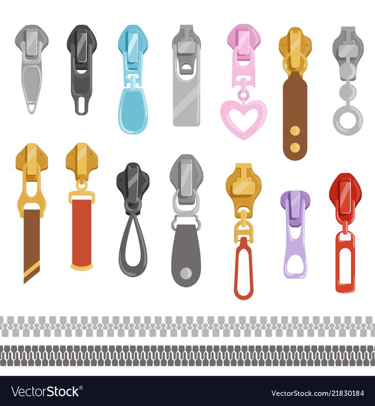 When the zipper is closed, start the machine.
5. Strong test of slider lock
The slider is self-locking in the middle of the connecting teeth. The zipper teeth are divided into left and right parts. Stretching the left and right parts of the zipper can test the locking strength and resistance of the internal components of the slider.
6.Crosswise Strength of Separating Unit
The zipper is locked and the two sides of zipper separating unit are fixed by the tester gripper. Stretch the two sides of zipper separating unit to test its resistance to external force damage
GESTER is professionally engaged in Testing Equipment with 20+ years experience, insists on the use of high-quality materials and advanced technology to manufacture textile testing instruments. Gester’s zipper tester can test zippers well.
GESTER
A. Zipper Rotation Test Machine GT-C39B
Zipper Testing Machine is used to do a variety of zipper reciprocating tests, by testing in a continuous back and forth action. The ultimate aim is to test the zipper to create a distance between joints, loose or connector failure, fluff, wear, etc.
B. Slide Fasteners Reciprocating Tester Zipper Testing Machine GT-C39A
Zipper Testing Machine is used to do a variety of zipper reciprocating tests, by testing in a continuous back and forth action. The ultimate aim is to test the zipper to create a distance between joints, loose or connector failure, fluff, wear, etc.
C. ASTM D2256 Single Yarn Strength Tester GT-A02A
Electronic Single Yarn Strength Tester is used to test the breaking strength and elongation percentage of various cotton, wool, linen, silk, chemical fiber, core-spun single yarn, pure or blending natural or chemical fiber yarns.
Electrolaboratory » Services of electrolaboratory » Measurement methods » Methodology for testing lightning protection systems
Specialists of our electrolaboratory will test the lightning protection of chimneys, industrial, administrative or residential buildings. We will check the condition of the lightning rod, the connection of the lightning rod with the down conductor and the down conductor with the lightning protection ground loop. All work is carried out with high quality and in a short time. It is very important to carry out a lightning protection test with the preparation of a "lightning protection test report" annually, before the start of the thunderstorm period. For any questions, please contact our office. 9
1. General provisions (RD 34.21.122-87).
The list of necessary technical measures is determined by the author, together with the foreman, in accordance with the requirements of SNiP 12-03-99.
When inspecting and checking the condition of lightning rods and down conductors on the roofs of buildings and structures, it is necessary to use assembler's safety belts. If the length of the belt sling is insufficient, it is necessary to use a safety rope previously fixed to the building structure. In this case, one of the persons conducting the tests slowly lowers or pulls the safety rope. When checking the welded joints of external conductors, the design of lightning rods, the tool (hammer) must be tied to prevent falling. When a thunderstorm approaches, all work must be stopped, the team removed from the workplace.
Protection against direct lightning strikes of buildings and structures , related to the lightning protection device to category I, must be carried out by separate rod or wire lightning rods
Protection against direct lightning strikes of buildings and structures , related to the device lightning protection to categories II and III, with a non-metal roof, should be made by stand-alone or installed on the protected object with rod or wire lightning rods.
With a roof slope of not more than 1:8, as a lightning rod, you can use a lightning protection mesh made of steel wire with a diameter of at least 6 mm with a mesh spacing for protection category II of not more than 6x6 m and 12x12 m for II I laid to ground electrodes at least, than 25 m along the perimeter of the building, they should be located no closer than 3 m from the entrances to buildings and in places inaccessible to the touch of people and animals. protection category. Down conductors from a metal roof or lightning protection mesh should be
In all the above cases, in addition, reinforced concrete foundations of buildings should be used as natural grounding conductors for lightning protection systems.
Dimensions of lightning rods, down conductors and grounding elements are given in table 1.
TABLE 1. Form of lightning rods, down conductors Outside In the ground Lightning rods (steel) - section not less than - length not less than 100 mm2 200 mm - - Rope lightning rods (steel stranded rope) - section not less than - length 35 mm2 depending on protection zone - - Round down conductors and jumpers (steel) - diameter not less than 6 mm - Round vertical electrodes (steel) - diameter at least - 10 mm Round horizontal electrodes (steel) * - diameter not less than - 10 mm Rectangular down conductors and earthing conductors (steel) - section not less than - thickness not less than 48 mm2 4 mm 160 mm2 4 mm *Only for equalizing potentials inside buildings and for laying external circuits at the bottom of the pit along the perimeter of the building Ohm. At the same time, the control of the transition resistance of bolted connections of lightning protection systems should be carried out annually with the beginning of the thunderstorm season. Lightning protection devices for buildings and structures must be tested, accepted and put into operation before the start of finishing work. Testing of lightning protection systems includes the following stages: 5.1. Method of measurement by the MRU-101 instrument. 5.1.1 Conditions for taking measurements and obtaining correct results Several conditions must be met in order to carry out measurements correctly. The meter automatically stops the measurement procedure in case of detection of the following abnormal situations: Situation Display symbols Explanations Noise voltage exceeds 24V LIMIT and UN Noise voltage exceeds 40V LIMIT and OFL is emitted a long beep is emitted No current current measurement -r- together with test socket symbol Test probes of required resistance not connected or test leads not connected to probes Test lead resistance exceeds 50 kΩ LIMIT together with the resistance value of the test probe in the additional display field Reduce the resistance value of the probe or increase the soil moisture near the probe Meters out of range OFL Additionally, the meter reports situations in which the measurement result cannot be recognized as correct: Situation Display symbols Explanations Measurement error due to probe resistance deviation of more than 30% LIMIT Battery cells exhausted BAT After turning on the meter with the R key, and after selecting the function with the rotary switch, the noise voltage value is shown on the display. If the noise voltage exceeds 24 V, it is not possible to make a measurement; in this situation, it is necessary to check whether the test leads are connected to the device, whether the power cable is connected to the mains, whether there is a short circuit or a break in the electrical insulation of the test leads, which may interfere with measurements. WARNING! The meter is designed to operate at noise voltages less than 40V. Applying voltages greater than 40V to any test jacks may damage the meter. Measurement starts after pressing the START key. The instrument is performing a measurement cycle and if none of the reasons for blocking described earlier is present. When measuring, the main field of the display displays the symbols D-D - the signal transmission of the version of this measurement stage, and in the field the current values of the parameters measured in this mode of the meter. After the end of the measurement, the values of the resistance value and the resistance of the measuring probe or the resistivity of the soil are displayed. The meter automatically selects the measuring range for each function. Three-pole circuit - the main circuit for measuring the resistance of lightning protection devices . The procedure is as follows: Figure 1. Three-pole circuit for measuring resistance Particular attention should be paid to the quality of the connection between the system under test and the test leads. The contact point must be free of paint, rust, etc. If the resistance of the meter probes is too high, the measured ground resistance will have an additional error. A particularly large measurement error is observed when a small value of the grounding device is measured, which has free contact with the ground (this situation occurs when the lightning rod is made as a good electrode, while the top level of the pound is dry and has poor conductivity). Under this condition, the ratio of the resistance of the measuring probes to the resistance of the investigated earth electrode is very large, and, as a result, the error depends on this ratio. Then, according to the formula given in the appendix "Technical Data", calculations can be made to evaluate the effect of the resistance of the probes, which is ensured by using the diagram given in the same appendix. water of the place where the probe is installed in the ground or by moving the probe to another place on the ground surface.0003 The test lead must also be checked for damage to the insulation or broken contact with the probe terminal, whether the clamp is connected to the test probe, and whether the contact has been corroded. In most cases, the measurement accuracy is sufficient. However, one must be aware of the magnitude of the error resulting from the measurement. In the event that it is necessary to make a measurement without additional error due to the resistance of the test leads, a four-pole circuit is used. To measure the resistance of the system, it is necessary: Figure 2. Four-pole circuit for measuring the resistance of a lightning protection system The list of necessary test tools and equipment is determined by the permitting worker together with the manufacturer. In general, a set of devices, tools, protective equipment should include the following: Works on checking the lightning protection systems of buildings are carried out according to a work permit or by order. The type of work registration is determined by the employee who has the right to issue orders and orders. The composition of the team must be at least two people: These persons must pass a medical examination for admission to climbing work and test knowledge of SNiP 12-03-99 in the scope of safety requirements for climbing work. A special entry is made about the permission to perform climbing work in the knowledge test log and in the certificate of checking values on the page "Certificate for the right to carry out special work". Based on the measurement results, a protocol of the established form is drawn up. Persons who have committed violations of the PTB or PTEEP, as well as those who have misrepresented the reliability and accuracy of measurements, are liable in accordance with the law and the regulation on a mobile electrical laboratory. Electrical laboratory in Dostoyanie residential complex find out more... Our electrical laboratory works in Mayak residential complex learn more... Our electrical laboratory works in Naslediye Residential Complex find out more... Request a call we will call you back! Only at New residential complex in the Moscow district Sokolinaya Gora!!! ...learn more... Electricity supply to residential buildings in the south-east of the capital restored . 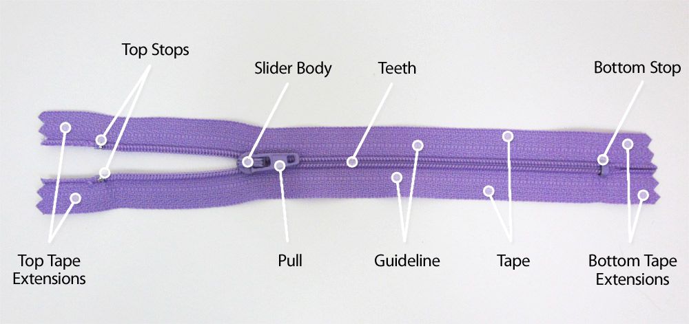 Welded seams should not have cracks, burns, lack of penetration of more than 10% of the length of the seam, unfilled craters and undercuts. The surface of the seam should be evenly scaly, without sagging. The length of the weld should be: for the design of circular sections of at least 6d (d is the diameter of the lightning rod, down conductor, ground electrode), rectangular - 2 V, where B is the width of the strip steel structures of lightning protection systems (clause 3.2 VSN 164-82, GOST 10434-82, SNiP Sh-33-76 section II).
Lightning protection systems are tested:
4. Testing.
 The value of this resistance should not exceed more than five times the results of measurements during acceptance tests. If the grounding conductor simultaneously performs the functions of protective (working) grounding of electrical installations of the building (structure) and grounding of the lightning protection system, additional measurement of its resistance is not required
 5. Measurement methods
![]()
 Other meter parameters can be displayed by pressing the SEL key.
 5.1.2 Measuring the resistance of a lightning protection system using a three-pole circuit.
 Specific values can be read from the main display field by pressing the SEL key
5.1.3 Measuring the resistance of a lightning protection system using a four-pole circuit
 The optimal position of the potential measuring probe is 62% of the distance between the current probe and the investigated lightning protection system
 6. Test tools and equipment
7. Safe working methods
 Persons from electrical personnel not younger than 18 years old, trained and certified for knowledge of PTB, PTEEP and this methodology, provided with tools, personal protective equipment, and overalls are allowed to work.
Blog
Electrical laboratory in Dostoyanie residential complex
Electrical laboratory in Mayak residential complex
Electrical laboratory in Naslediye Residential Complex
Didn't get through?
10%
call us
to receive a discount News
Residential complex Semyonovsky Park has a registration
Electricity supply restored in the south-eastern districts of Moscow
 .. more...
 Lighting of Moscow began 289 years ago year, continuous illumination of Moscow began ... more...
Lightning protection systems should be checked for operability from time to time. The need for such tests is dictated by the safety of both the building and the people in it. In addition, lightning rods are under the constant negative influence of environmental factors, which can lead to a deterioration in their functionality.
Inspection activities are usually divided into types:
Scheduled testing procedure is regulated by the standards established in Instruction RD-34.22.121-87. Checks are regulated by the provisions of the PUE (rules for the installation of electrical installations) and PTEEP (rules for the technical operation of electrical installations of consumers). For outdoor protective devices, the rules are specified in paragraph 1.14 of RD-34.22.121-87.
In accordance with the specified standards, all protected objects are divided into categories. Based on the category established for the building or structure, the frequency of inspection of the lightning protection system is established. For example, for buildings of the first and second category, tests should be carried out every year before the onset of the thunderstorm season. The third category refers to facilities with a minor hazard. In this case, inspections should be carried out every three years.
Checks outside the planned schedule are carried out in the following cases:
Carried out when the protected building is handed over to the customer. Start-up testing is carried out immediately after the completion of the main construction work or according to a previously agreed schedule for the reconstruction of the facility.
The test results are documented. Based on the conclusion, the operation of the system begins.
The task of scheduled, introductory and extraordinary measurements of resistance and inspections of lightning protection devices for other parameters is to assess the compliance of the existing parameters with the regulations and design documents. For this purpose, the quality of installation work is examined, the state of local sections of the system, contacts is determined. The goals of testing, the content and scope of tasks depend on the parameters of the object and the design features of the protection system.
Tests are carried out according to a certain algorithm:
Earthing resistance measurements of lightning rods are carried out separately for each device. The final indicator should differ no more than five times from the data obtained during the introductory tests. If the grounding conductor performs a related task (working grounding of the building and lightning protection system), there is no need to measure the resistance.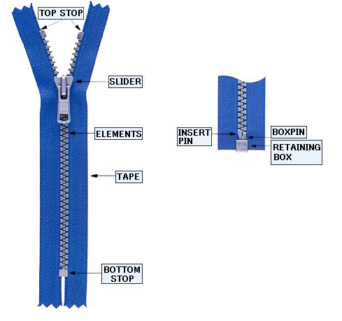
To obtain the most accurate results, scheduled and start-up inspection work is carried out during the lowest level of humidity in the soil adjacent to the building. In regions belonging to permafrost zones, measurements are carried out during the period of maximum freezing of the earth.
Please note! When testing the system, the level of atmospheric pressure is taken into account. This parameter is secondary, but it is included in the final protocol.
High-precision equipment type M-416 is used for testing. The device is used in conjunction with an electrical safety data meter for equipment and electrical installations (MPI-511). At the same time, existing standards allow the use of other measuring instruments with similar capabilities.
The resistance of the functional elements of the protective system is measured by the MRU-101 instrument. The device is capable of automatically stopping the test in case of emergency and displays the following indicators on the monitor:
The noise voltage value is set by pressing the R button or by selecting the measurement function by turning the device switch.
The received data is not recognized as correct if the equipment has detected the following situations:
In the absence of grounds for blocking or small deviations of the input data from the standards, the MTU-101 takes measurements and displays the following data on the display:

Please note! The measurement range for each parameter is automatically determined by the equipment.
For measuring the resistance of a lightning protection system, the method is considered basic. The work is carried out as follows:
Set rotary switch to position RE 3p. Further, measurements begin after pressing the START key.
After the end of the procedure, the display shows the resistance of the earth electrode (RE) and the data received from the probes. The distance between the potential probe and the protective system is reduced to one meter. After doing another freeze. If the results differ by more than 3%, move the current probe further away. The measurement is repeated until an acceptable ratio of the obtained data is obtained.
Three-pole measurements involve several considerations. For example, with an increased resistance of the probes, this indicator for grounding is set with a certain error. The same should be said about the measurements of the resistance of the ground loop, which is in free contact with the ground. The reason for the existing errors is the excessively high ratio of the resistances of the probes and the ground electrode.
To improve the accuracy of the data obtained, it is necessary to achieve better contact of the probes with the ground. For this purpose, the probes are moved to another, more humid place. An alternative to this solution is to artificially moisten the soil before performing the test. In addition, you need to inspect the measuring conductors to make sure that the insulating material is intact, there are no traces of rust, and check the contacts with the probe terminals.
Please note! The results of all additional procedures are recorded in the final protocol.
Compliance with all recommended conditions allows you to get fairly accurate results (taking into account the total measurement error). It should be borne in mind that a correct assessment of the influence of the resistance of the probes requires additional calculations.
If particularly high accuracy of results is required, errors must be eliminated. In this case, the use of a four-pole circuit will help.
The measurements are carried out as follows:

The measuring probe is moved one meter from the protective system. After that, the measurements are made again. The results obtained are interpreted in the same way as in the case of a three-pole system. At the end of the study, the data is recorded in the final protocol.
Please note! Regardless of the scheme used, the distance of the potential probe to a value equal to 62% of the distance between the system under study and the current probe is considered the norm.
The main document indicating the reliability of the data obtained is the test report of the protective system. This document displays all the required performance data.