Our M12 FUEL™ Low Speed Tire Buffer Kit is the world's first cordless tire buffer, delivering performance, control, and runtime to replace pneumatic solutions in the shop. With our MILWAUKEE® POWERSTATE™ Brushless Motor, this tire repair tool provides the performance and size professional tire technicians demand. The tire buffer has the power to complete passenger, light truck, and commercial flat tire repairs. With 2-Mode Drive Control™, you can avoid costly mistakes by performing consistent flat tire repairs with a dedicated Buffing and Drilling mode. With the runtime to perform up to 30 flat tire repairs on a single XC4.0Ah battery, this tire buffer increases productivity with less downtime. This cordless tire buffer provides you with greater access and mobility, eliminating the frustrations of hoses and compressors.
POWERSTATE™ Brushless Motor delivers the power to complete passenger, light truck, and commercial flat repair
REDLINK PLUS™ Electronic Intelligence enables advanced communication between your batteries and tools, allowing for unmatched levels of performance, protection, and productivity.
Dedicated buffing and drilling 2-Mode Drive Control™ avoids costly mistakes and performs more consistent flat repairs
Unmatched Performance with the runtime to complete up to 30 flat repairs on a single XC4.0Ah battery
Eliminates Compressors and Hoses, providing greater productivity, portability, and lower cost of ownership
LED light to illuminate the work area
Premium rubber overmold withstands corrosive materials and provides increased comfort when in use
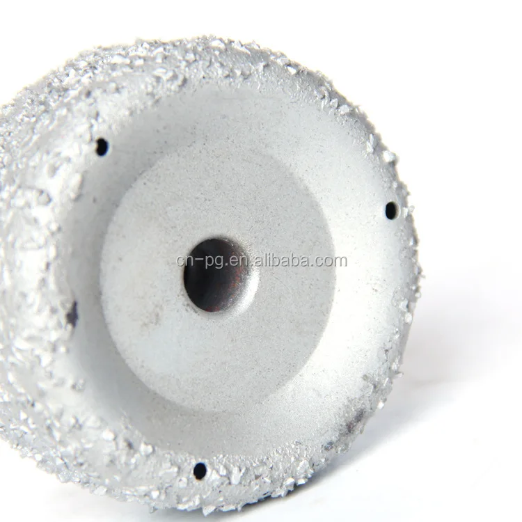
Quick change collet for fast and easy change of buffing wheel or carbide cutter
REDLITHIUM™ batteries deliver more work per charge and more work over the life of the battery
Compatible with all M12™ batteries & chargers
Download Operator’s Manual Download Service Parts List
Battery Specifications
Voltage
12V
Battery Type
12 Volt Lithium Ion
Product Specifications
Cordless Feature
Cordless
Tool Warranty
3 Year Limited Warranty
Power Source
Cordless
Motor Type
POWERSTATE Brushless
Length
10.
1 in
Weight
1.9 lb
Height
2.4 in
Width
2.0 in
Collet Size
7/16"
RPM
0 – 2,500
Brushless
Yes
Battery System
M12
M12 FUEL Low Speed Tire Buffer (Kit)
The M12 FUEL™ Low Speed Tire Buffer is the world's first cordless tire buffer, delivering performance, control and runtime to replace pneumatic solutions in the shop. With the POWERSTATE™ Brushless Motor, this tool delivers the performance and size professional tire technicians demand. The tire buffer has the power to complete passenger, light truck, and commercial flat repair. WIth 2-Mode Drive Control™, avoid costly mistakes by performing consistent flat repairs with a dedicated Buffing and Drilling mode. With the runtime to perform up to 30 flat repairs on a single XC4.0Ah battery, this tire buffer increases productivity with less downtime. The cordless tire buffer provides you with greater access and mobility, eliminating the frustrations of hoses and compressors. In addition to the tool, this kit includes one M12™ REDLITHIUM™ CP2.0Ah battery and one XC4.0Ah.
Features
POWERSTATE™ Brushless Motor delivers the power to complete passenger, light truck, and commercial flat repair
REDLINK PLUS™ Electronic Intelligence enables advanced communication between your batteries and tools, allowing for unmatched levels of performance, protection, and productivity.
Dedicated buffing and drilling 2-Mode Drive Control™ avoids costly mistakes and performs more consistent flat repairs
Unmatched Performance with the runtime to complete up to 30 flat repairs on a single XC4. 0Ah battery
Eliminates Compressors and Hoses, providing greater productivity, portability, and lower cost of ownership
LED light to illuminate the work area
Premium rubber overmold withstands corrosive materials and provides increased comfort when in use
Quick change collet for fast and easy change of buffing wheel or carbide cutter
REDLITHIUM™ batteries deliver more work per charge and more work over the life of the battery
Q: Does the quick-change adapter for use with buffing wheels come with the bare tool and the kit?
A: Yes, the quick-change adapter comes with bare tool, kit, and commercial combo kit. The quick-change adapter can be combined with all common buffing wheels used by pneumatic low speed tire buffers today.
Q: Is this tool a full pneumatic low speed tire buffer replacement?
A: Yes, the M12 FUEL™ Low Speed Tire Buffer can complete all buffing and drilling applications in passenger, light truck, and commercial truck tires that are currently performed by the most common pneumatic low speed tire buffers in the market today
Q: Is this tool a pneumatic replacement for high speed tire buffers?
A: No, pneumatic high speed tire buffers are used for retread/recapping tires which is a completely different application than flat repair. High speed tire buffers operate at speeds of up to 22,000 RPM and should not be used for flat repair applications due to risk of burning or scorching the tire.
Q: What is the 2-Mode Drive Control™ on this tool?
A: The tool has 2 dedicated modes that the user can switch between. A buffing mode at 2,500 RPM & a drilling mode at 1,200 RPM. These modes are optimized to deliver the needed power and speed to complete the application safely and efficiently, increasing user control. Pneumatic tools have no way to provide this
Q: Why is Milwaukee® offering their own buffing wheel accessories?
A: We saw significant variation in buffing wheel performance based on brand, shape, size, and grit in the market today. Therefore, we wanted to deliver a buffing wheel accessory that maximized performance during buffing applications and further enhances the productivity of the user when used with our tool
Q: Will the tool be compatible with existing buffing wheel and carbide drilling bit accessories used by pneumatic low speed tire buffers?
A: Yes, the tool is compatible with all common buffing wheel & carbide drill bit accessories in the market used by pneumatic low speed tire buffers today
Q: What is the warranty on the tool?
A: The M12 FUEL™ Low Speed Tire Buffer has a 3-year warranty. Milwaukee® warranty standards apply, including evaluation of wearable components and extreme use. This is higher than most pneumatic low speed tire buffers which typically only offer a 1-year warranty.
Q: Will a separate rubber boot be available for the M12 FUEL™ Low Speed Tire Buffer?
A: No, a separate rubber boot is not currently available. The tool uses a premium rubber overmold which provides improved resistance to shop environment and chemicals.
Q: Why does this tool come with both the CP2.0Ah & XC4.0Ah battery pack?
A: The tool can perform all buffing & drilling applications for passenger through commercial with the CP2.0Ah pack. However, the XC4.0Ah pack is included to
deliver more power while drilling, if needed, for the heaviest commercial truck tires such as dump trucks and haulers.
User Manual milwaukee M12 FTB Fuel Low Speed Tire Buffer
User Manual milwaukee M12 FTB Fuel Low Speed Tire Buffer
.
GENERAL POWER TOOL SAFETY WARNINGS
Read all warnings, instructions, illustrations, and specifications provided with this power tool. Failure to follow all of the instructions below may result in electric shock, fire and/or serious injury. Retain all warnings and instructions for future reference. The term “power tool” in warnings refers to your corded (corded) power tool or cordless (cordless) power tool.
WORK AREA SAFETY
Keep your work area clean and well lit. Cluttered or dark places can cause accidents.
Do not use power tools in explosive environments, such as in the presence of flammable liquids, gases or dust. Power tools create sparks which may ignite the dust or fumes.
Keep children and bystanders away when operating power tools. Distraction can lead to loss of control.
ELECTRICAL SAFETY
Power tool plugs must match the outlet. Do not modify the plug in any way. Do not use adapter plugs with grounded power tools. Unmodified plugs and suitable outlets will reduce the risk of electric shock.
Avoid body contact with grounded or grounded surfaces such as pipes, radiators, stoves and refrigerators. There is an increased risk of electric shock electric shock if your body is grounded.
Do not expose power tools to rain or moisture. Water entering a power tool increases the risk of electric shock.
Do not overuse the cord. Never use the cord to carry, pull or disconnect a power tool. Keep cord away from heat, oil, sharp edges or moving parts. Damaged or entangled cords increase the risk of electric shock.
When using a power tool outdoors, use an extension cord suitable for outdoor use. Using a cable suitable for outdoor use reduces the risk of electric shock.
If you are using a power tool in an advertisement If this cannot be avoided, use a source protected by a residual current device (RCD). The use of an RCD reduces the risk of electric shock.
PERSONAL SAFETY
Stay alert, watch what you are doing and use common sense when operating a power tool. Do not use a power tool if you are tired, under the influence of drugs, alcohol or medication. A moment of inattention while operating a power tool can result in serious injury.
Wear personal protective equipment. Always wear safety goggles. Protective equipment such as a respirator, non-slip safety shoes, hard hat or hearing protection, used in appropriate conditions, will reduce the risk of injury.
Prevention of unintended start. Before connecting to a power source and/or battery pack, or lifting or carrying the tool, make sure the switch is in the off position. Carrying power tools with your finger on the switch or supplying power to power tools with the switch turned on can cause accidents.
Remove the adjusting key or wrench before turning on the power tool. A wrench or wrench left on a rotating part of the power tool can cause injury.
Don't overdo it. Always stand on your feet and keep your balance. This allows better control of the power tool in unexpected situations.
Dress appropriately. Do not wear loose clothing or jewelry. Keep hair and clothing away from moving parts. Loose clothing, jewelry or long hair can get caught in moving parts.
If devices are provided for connecting dust collectors and dust collectors, make sure they are connected and used properly. The use of a dust collector can reduce the risk associated with dust.
Don't let the familiarity gained from frequent tool use let you relax and ignore the principles of tool safety. Careless action can lead to serious injury in a fraction of a second.
USE AND CARE OF THE POWER TOOL
Do not apply force to the power tool. Use the correct power tool. The right power tool will do the job better and safer at the rate it was designed for.
Do not use the power tool unless the switch turns it on and off. Any power tool that cannot be operated with the switch is dangerous and must be repaired.
Disconnect the plug from the power source and/or remove the battery, if disconnected, from the power tool before making any adjustments, changing accessories, or storing the power tool. These preventive safety measures reduce the risk of starting the power tool accidentally.
Store idle power tools out of the reach of children and do not allow anyone unfamiliar with the power tool or these instructions to operate the power tool. Power tools are dangerous in the hands of untrained users.
Take care of power tools and accessories. Check for skewed or seized moving parts, broken parts, or any other condition that may affect the operation of the power tool. If damaged, have the power tool repaired before use. Many accidents are caused by poorly maintained power tools.
Keep cutting tools sharp and clean. Properly maintained cutting tools with sharp cutting edges are less likely to seize and are easier to control.
Use power tools, accessories, attachments, etc. in accordance with these instructions, taking into account the working conditions and the work to be performed. Use of the power tool for operations other than those intended may result in a hazardous situation.
Keep handles and gripping surfaces dry, clean and free of grease. Slippery handles and gripping surfaces make it difficult to safely handle and control the tool in unexpected situations.
USE AND CARE OF THE BATTERY
Charge only with a battery charger specified by the manufacturer. A charger that is suitable for one type of battery pack may create a risk of fire when used with another battery pack.
Only use power tools with specially designed batteries. Use of any other battery packs may create a risk of injury or fire.
When the battery is not in use, keep it away from other metal objects such as paper clips, coins, keys, nails, screws or other small metal objects that can connect one terminal to another. Shorting the battery terminals together may cause burns or fire.
Battery may leak liquid in adverse conditions; avoid contact. In case of accidental contact, rinse with water. If liquid gets into eyes, additionally seek medical attention. Liquid leaking from the battery may cause irritation or burns.
Do not use a damaged or modified battery or tool. Damaged or modified batteries may behave unexpectedly, resulting in a fire, explosion, or risk of injury.
Do not expose the battery or tool to fire or extreme temperatures. Exposure to fire or temperatures above 130 °C (265 °F) may cause an explosion.
Follow all charging instructions and do not charge the battery or tool outside the temperature range specified in the instructions. Incorrect charging or at temperatures outside the specified range may damage the battery and increase the risk of fire.
Services
Have your power tool serviced by a qualified repair person using only identical replacement parts. This will ensure the safety of the power tool.
Never repair damaged batteries. Servicing of battery packs should only be performed by the manufacturer or authorized service providers.
SPECIFIC SAFETY REGULATIONS FOR BUS BUFFER
General safety warnings for grinding, sanding and polishing operations:
This power tool is designed to be used as a grinding, grinding or polishing tool. Read all safety warnings, instructions, illustrations, and specifications provided with this power tool. Failure to follow all of the instructions below may result in electric shock, fire and/or serious injury.
Do not use accessories not specifically designed or recommended by the tool manufacturer. Just because an accessory can be attached to your power tool does not guarantee safe operation.
The rated speed of the grinders must be at least equal to the maximum speed marked on the power tool. Sanding accessories running faster than their rated speed may break and fly apart.
The outside diameter and thickness of the accessory must match the power of your power tool. Wrong-sized accessories are not properly controlled.
The size of the wheel arbor, grinding drum or any other attachment must be suitable for the power tool's spindle or collet. Accessories that do not fit the power tool's mounting hardware will lose balance, vibrate excessively, and may result in loss of control.
Arbor-mounted wheels, grinding drums, cutters or other accessories must be fully inserted into the collet or chuck. If the mandrel is not held sufficiently and/or the wheel offset is too long, the installed wheel may become loose and fly out at high speed.
Do not use a damaged accessory. Before each use, check accessories such as abrasive wheels for chips and cracks, sanding drum for cracks, tears or excessive wear. If the power tool or accessory has been dropped, inspect it for damage or install an undamaged accessory. After inspecting and installing the nozzle, step away from the plane of the rotating nozzle and turn on the power tool at maximum idle speed for one minute. Damaged accessories usually break during this test time.
Wear personal protective equipment. Depending on the application, use a face shield, goggles, or goggles marked AS/NZS 1337.1 conformity. If necessary, wear a dust mask, hearing protection, gloves, and a work apron capable of stopping fine abrasive particles or pieces of workpiece. Eye protection must be capable of stopping flying debris generated by various operations. A dust mask or respirator must be able to filter particles generated by your work. Prolonged exposure to high intensity noise can cause hearing loss.
Keep bystanders at a safe distance from the work area. Everyone entering the work area must wear personal protective equipment. Fragments of a workpiece or broken fixture may fly out and cause injury outside the immediate area of effect.
Hold the power tool only by insulated gripping surfaces when performing operations where the cutting tool may touch hidden wiring. Touching a cutting tool to a “live” wire can make exposed metal parts of the power tool “live” and cause an electric shock to the operator.
Always hold the tool firmly in your hand(s) while starting. The moment the motor reacts when it accelerates to full speed, it can cause the tool to twist.
Use clamps to support the workpiece whenever possible. Never hold a small workpiece in one hand and a tool in the other while working. Clamp Machining a small workpiece allows you to use your hand(s) to control the tool. Round material such as dowels, pipes or tubes tend to roll while cutting and can cause the bit to stick or jump towards you.
Never put down the power tool until the tool has come to a complete stop. A rotating accessory can grip the surface and take the power tool out of your control.
After changing bits or making any adjustments, make sure that the collet nut, chuck, or any other adjustment devices are securely tightened. Loose control devices can move unexpectedly causing loss of control, loose rotating components are violently thrown.
Do not switch on the power tool by carrying it on its side. Accidental contact with a rotating accessory may catch on your clothing and pull the accessory into your body.
Clean the ventilation openings of the power tool regularly. The motor fan draws dust into the case, and excessive accumulation of metal powder can cause an electric shock hazard.
Do not use power tools near flammable materials. Sparks can ignite these materials.
Do not use accessories that require liquid coolant. Use of water or other liquid coolants may result in electric shock or electric shock. Kickback and Related Warnings Kickback is a sudden reaction to a pinched or seized rotating wheel, sanding belt, brush, or any other attachment. Pinching or binding causes the rotating tool to stop quickly, which in turn causes the power tool to move uncontrollably in the opposite direction of the tool rotation. For the former, that is, if the abrasive wheel gets caught or pinched by the workpiece, the edge of the wheel that enters the pinch point can cut into the surface of the material, causing the wheel to skid or slip out. The wheel may bounce towards or away from the operator, depending on the direction of travel of the wheel at the pinch point. Under these conditions, abrasive wheels can also break. Kickback is the result of power tool misuse and/or improper operating procedures or conditions and can be avoided by taking the proper precautions listed below.
Hold the power tool firmly and position your body and hand so that you can resist the kickback force. The operator can control the kickback force if appropriate measures are taken.
Take extra care when working around corners, sharp edges, etc. Avoid bouncing or snagging on the attachment. Corners, sharp edges, or bouncing can catch on a rotating accessory and cause loss of control or kickback.
Do not attach a notched saw blade. Such blades create frequent kickback and loss of control.
Always feed the drill into the material in the same direction as the cutting edge exits the material (in the same direction as the chips). Feeding the tool in the wrong direction causes the drill tip to pop out of the work and pull the tool in the direction of that feed.
When using rotary files, high-speed cutters or tungsten carbide cutters always provide reliable work. These wheels will seize if they are slightly warped in the groove and may cause kickback. When gripping a cutting wheel, the wheel itself usually breaks. When a rotary file, high-speed cutter, or tungsten carbide cutter catches it, it may jump out of the groove and you may lose control of the tool. Additional safety warnings To reduce the risk of injury, wear appropriate respiratory protection or use a suitable dust removal solution when working in dusty conditions.
Do not use the battery as leverage. Use the correct power tool for your application. The right power tool will do the job better and safer at the rate it was designed for.
Always use common sense and be careful when using tools. It is impossible to foresee every situation that could lead to a dangerous outcome. Do not use this tool if you do not understand these operating instructions or if you feel that the operation is beyond your ability; contact MILWAUKEE® Tool or a trained professional for more information or training.
Watch labels and nameplates. They carry important information. If they are unreadable or missing, contact a MILWAUKEE® Service Center for a replacement. Some dust from sanding, sawing, sanding, drilling and other construction activities contains chemicals known to cause cancer, birth defects or other reproductive harm. Some former & lesser of these chemicals are:
lead from lead based paint
crystalline silica from brick, cement and other stone products, and
arsenic and chromium from chemically treated wood. Your risk from these exposures varies depending on your exposure to these chemicals: work in a well-ventilated area and work with approved protective equipment such as respirators specifically designed to filter out microscopic particles.
ADDITIONAL SAFETY INSTRUCTIONS
To reduce the risk of fire, personal injury, and product damage due to a short circuit, never immerse a tool, battery, or charger in liquid or allow liquid to flow inside them. Corrosive or conductive liquids such as sea water, some industrial chemicals, bleaches or products containing bleach, etc. may cause a short circuit.
Do not charge non-rechargeable batteries.
SYMBOLOLOGY
V Volt DC n XXXX min Rated revolutions per minute (rpm) Read operator's manual Wear safety goggles. Regulatory Compliance Mark (RCM). This product complies with applicable regulatory requirements. Do not dispose of power tools with household waste. End-of-life electrical tools and electronic equipment must be collected separately and returned to an environmentally friendly recycling facility.
CHARACTERISTICS
Cat. No. …………………………………………………M12 FTB volt. ………………………………………………………….12 V DC Battery type ……………………………………………….. M12™ Charger type……………………………………………. M12™ Nominal RPM………………………………….. 0-1200/2500 Quick Change Adapter Maximum Polisher Diameter……………..80mm (3-1/8″) Maximum drill head diameter………………… 9.5 mm (3/8″) Recommended Ambient Operating temperature…………….. .. -17°C to 51°C
FUNCTIONAL DESCRIPTION
how often do you do this type of work. Reduce
Tsang
Regime selector
Fuel level indicator
Processing
LED
Switch Switches
Clovard Switches
Installation For specific charging instructions, see the operator's manual that came with your charger and battery.
Battery removal / installation
To remove the battery, press the release buttons and remove the battery pack from the tool.
Always remove the battery before replacing or removing accessories. To insert the battery, insert the block into the body of the tool. Make sure it is securely locked in place.
Use only accessories specifically recommended for this tool. Others may be dangerous. Use only accessories with a maximum safe operating speed that is at least equal to the maximum speed marked on the power tool. This speed depends on the strength of the accessory, which provides a reasonable degree of safety. It does not mean the best or most efficient performance. Do not exceed the maximum safe operating speed.
Accessories
Tips, cones, plugs, grinding and detachment circles should be protected from:
Humidity and extreme moisture content
Any type of solvent
Tempensions
acute wheels must be stored:
in an organized manner so that points, cones, plugs or wheels can be removed without disturbing or damaging other points, cones, plugs or wheels
with safety information
wheels DO NOT drop, roll or push. Discard tips, cones, plugs, or wheels that have been dropped, rolled, bumped, subjected to extreme temperature changes, or come into contact with solvents or moisture.
Installing accessories
Remove dust and debris from the collet body before installing the adapter.
Insert the collet with the nut secured into the collet body. Thread the collet nut onto the spindle, but do not tighten yet.
Clean the auxiliary arbor, then insert it into the collet at least 25 mm (1 in.). The mandrel will protrude approximately 13 mm (1/2″) above the collet and accessory.
While holding the spindle shaft with a 1/2" open end wrench, securely tighten the collet nut with a 11/16" open end wrench.
When removing an accessory, reverse the procedure.
To reduce the risk of injury, always tighten the collet securely on grinders and clean arbors before inserting them into the collet. Otherwise, high-speed rotation of the tool may cause the bit to fly out of the collet.
OPERATION
To reduce the risk of injury, always wear appropriate eye protection marked in accordance with AS/NZS 1337.1.
When working in dusty conditions, wear suitable respiratory protection or a suitable dust remover.
Fuel gauge
Turn on the tool to check the battery level. The fuel gauge will light up for 2-3 seconds. When less than 10% charge is left, 1 indicator on the fuel gauge will flash 4 times. To signal the end of charging, 1 indicator on the fuel gauge will flash 8 times and the tool will not start. Charge the battery. If the battery gets too hot, the fuel gauges will flash alternately and the tool will not work. Let the battery cool down.
Using the mode switch
Mode selection button or used to adjust the rotation speed (RPM) for the application: To select the mode: Press the mode switch forward to select polish. mode. It is used inside the inner shell of a tire. Press the mode select button down to select the drilling mode. mode. This application is used on the inside and outside of the tire.
Mode
Drilling mode
Politing mode
RPM
0-1,200
0-2500
9000 9000 9000 9000 9000
224
If you have just installed an accessory or are starting a work period, test it by letting it run for one minute before applying it to the workpiece. Never use an accessory that has been dropped. Unbalanced or damaged accessories can damage the workpiece, damage the tool, and cause stress that can lead to accessory failure.
Use a clamp, vise, or other practical means to hold your work.
To start the tool, slide the switch lock forward (1) and press the paddle switch (2). NOTE. When the switch is pressed, the LED lights up.
Allow the tool to reach full speed before starting work.
Increase or decrease pressure on the switch to change speed. The further the switch is pressed, the faster the speed.
Control pressure and surface contact between accessory and workpiece. Never knock accessories at work. Too much pressure causes accessory failure or speed reduction.
Release the switch to stop the tool. Make sure the tool has come to a complete stop before putting down the tool.
If the tire buffer starts to vibrate, stop the engine immediately and check if the accessory is dull. Blunt accessories will cause the tool to vibrate and may cause the collet to come off the tool. Always replace or sharpen dull accessories. Accessories designed for specific purposes. Use tips, cones, plugs, grinding wheels and cut-off wheels only for the purpose for which they were designed. Follow the manufacturer's instructions for care and use.
SERVICE
To reduce the risk of personal injury, always unplug charger and remove battery from charger or tool before performing any maintenance. Never disassemble the tool, battery or charger. Contact a MILWAUKEE® Service Center for ALL repairs.
Service Tool
Keep tool, battery and charger in good condition by performing a regular maintenance program. Inspect your tool for problems such as excessive noise, misaligned or seized moving parts, broken parts, or any other condition that could affect tool performance. Return tool, battery, and charger to a MILWAUKEE® Service Center for repair. After six months to one year, depending on use, return the tool, battery, and charger to a MILWAUKEE® Service Center for inspection. If the tool does not start or run at full power with a fully charged battery, clean the contacts on the battery. If the tool still does not work properly, return the tool, charger, and battery to a MILWAUKEE® Service Center for repair.
To reduce the risk of injury or damage, never immerse a tool, battery, or charger in liquid or allow liquid to flow inside them.
Cleaning
Remove dust and debris from air vents. Keep your pens clean, dry and free of grease. Use only mild soap and cloth for cleaning as some cleaners and solvents are harmful to plastic and other insulated parts. Some of these include gasoline, turpentine, lacquer thinner, paint thinner, chlorinated cleaning solvents, ammonia, and household cleaners containing ammonia. Never use flammable or combustible solvents near tools.
Repair
Return the tool, battery and charger to the nearest authorized service center for repair.
ACCESSORIES
Use only recommended accessories. Others may be dangerous. A complete list of accessories can be found online at www.milwaukeetool.com.au/ www.milwaukeetool.co.nz or contact your distributor.
WARRANTY - AUSTRALIA & NEW ZEALAND
See Australia & New Zealand Warranty included with tool. This warranty only applies to product sold by authorized dealers in Australia and New Zealand.
SERVICE - AUSTRALIA & NEW ZEALAND
MILWAUKEE® prides itself on making a premium product that is Nothing But Heavy DutyTM. Your satisfaction with our products is very important to us! If you experience any problems with the operation of this instrument, contact your authorized MILWAUKEE® dealer.
For a list of MILWAUKEE® Dealers, Warranty Agents, or Service Agents, contact MILWAUKEE® Customer Support or visit our website. (Australia toll free 1300 645 928) (New Zealand toll free 0800 645) or visit milwaukeetool.com.au/milwaukeetool.co.nz.
Miluoi power tool Corporation 13135 West Lisbon Road, Bruckfield, Wisconsin, USA 53005
Milwaukee Tool (Australia) KELlets-Road, Rowville, Victoria, 3178 Melbourne, Australia 9000, Australia , Austral New Zealand) 274 Church Street, Penrose
Tool Milwaukee | Milwaukee Tool Australia Official Site | Nothing but HEAVY DUTY®
The characteristic of rubber deformation under compression is fully used here. The rapid growth of deformations is accompanied by a gradually increasing load, and the rubber buffer becomes the stiffer, the more it is deformed.
Typical body buffers are shown in fig. 401, and for the chassis - in fig. 402. The main dimensions of buffers for bodies are given in Table. 56.
Characteristics of round buffers "Megulastic" (Fig. 403) is given in Table. 57. Dimensions of round buffers are chosen so that
the maximum deformation of rubber under the influence of dynamic load does not exceed the allowable limits [103, 127, 128].
The deformation of a rubber buffer loaded with a vertical dynamic force (Fig. 404) is calculated [58] using the following formula:
where / is the buffer deformation under dynamic load, cm; K is the height of the fall of the load G on the buffer, cm; G is the mass of the load falling on the buffer, kg; s din - dynamic stiffness 6v (beoa, kgf / cm, and - max
small "permissible buffer compression, N, given in table. 57; f d - deformation of the buffer during compression by force P d > given in Table 57. a is the correction factor for dynamic loads given in Table 58.
57 refer to buffers
made of rubber with a hardness of HSh 60. When it is necessary to use rubber with a different hardness, select the correction factor corresponding to this hardness from table. 58. The resulting deformation of the buffer should not exceed 25% of the height of the rubber.
Table 56
Basic dimensions of round buffers for bodies, mm
D
h
d x
d
Dt
25
10 15 20
8
4
15
5
30
25
18
6
30
22
40
20 25 30
12
5
30
10
403. Designations of the main dimensions of the buffers "Megulastic" [58]
The deformation of the rubber buffer (in cm), loaded with a dynamic horizontal force (Fig. 405), is calculated using the following formula:
where V is the speed of the impacting mass when it meets an obstacle, cm/s; g is the acceleration due to gravity 981 cm/s 2 .
Table 57
Characteristics of round buffers [58]
Dimensions, mm
Compression load, N
Deformation, cm
D
n
S
G
1
d nax
t
Pd check
f d
16
4
1
M4
10
370
0. 3
15
13
1
M4
15
4
70
1.2
15
6
1
M4
15
110
0.5
15
30
-
M4
15
70
2.8
20
16
1.5
Mb
18.5
5.8
130
1.5
26
18.0
1.5
Mb
22
270
1. 5
26
18.0
1.5
Mb
10
270
1.5
30
16
2
M8
13
370
1.4
30
26
2
M8
23
7.4
330
2.4
35
40
2
M8
23
520
3.8
40
26
2.5
M10
27.5
2. 8
10.0
740
2.4
40
30
2.5
M8
22.5
7.9
700
2.8
45
45
2.5
M12
25.5
760
-
50
36
2.5
M10
27.5
2.8
10.0
1000
3.4
50
12
2.5
M10
27.5
3500
1.0
50
21
2. 5
M10
27.5
2.8
10.0
1400
1.9
70
55
3
M12
37
3.8
10.5
2750
5.2
75
20
3
M12
37
3.8
10.5
4000
1.7
75
30
3
M12
37
3.8
10.5
3 200
2.7
75
45
3
M12
37
3. 8
10.5
2400
4.2
100
56
4
M16
46
4.2
3 100
4.6
100
69
4
M16
46
4.2
15.8
4 300
6.5
160
65
4
M16
46
4.2
15.8
14000
6.1
200
45
6
M16
44
15.8
35,000
3.9
405. Buffer loaded with a horizontal dynamic force [58]
404. Buffer loaded with vertical dynamic force [58]
Fig. Fig. 406. Bumper of a Swedish passenger car SAAB (length about 2 m, rubber weight about 4 kg)
Pic. 407. Bumper of a Swedish car VOLVO
Deformation during a horizontal impact should not exceed the values given for f d in Table 57, more than 50%.
Increasingly, front and rear rubber bumpers are used in passenger cars (Fig. 406 and 407) [11-15, 23, 135]. For example, Ford uses natural rubber bumpers, while others use synthetic rubber. The introduction of bumpers of this type leads to greater traffic safety. Studies initiated by US insurance companies have shown that in the US compensation,
paid out for minor injuries in road accidents eats up billions of dollars. The same situation exists wherever there is heavy traffic. Minor injuries usually occur when an accident occurs at low vehicle speeds.
In order to improve traffic safety, in 1973, the United States introduced the MVSS215 safety regulation, which requires that if a car traveling at a speed of 2. 2 m / s (8 km / h) hits a stationary obstacle, the functioning of the steering device should not be impaired , brakes, drivetrain, suspension, fuel system, exhaust and cooling systems.
Lighting devices, direction indicators, hood, trunk roof, doors should also remain in working order. It is expected that these requirements will soon be tightened, since the critical speed at the time of the collision should increase to 4.4 m/s (16 km/h).
Automotive companies in Europe, especially those exporting their products to the USA, strive to ensure that their cars also meet these requirements. This can be achieved by skillfully designing rubber bumpers. Often they are * multi-chamber rubber beams with HSh 70-90, fixed on fixing steel beams.
The rubber used to produce these safety bumpers should have high aging resistance and little change in elasticity over a temperature range of -40 to +80°C. for their manufacture in vehicles.


 1 in
1 in
 The tire buffer has the power to complete passenger, light truck, and commercial flat repair. WIth 2-Mode Drive Control™, avoid costly mistakes by performing consistent flat repairs with a dedicated Buffing and Drilling mode. With the runtime to perform up to 30 flat repairs on a single XC4.0Ah battery, this tire buffer increases productivity with less downtime. The cordless tire buffer provides you with greater access and mobility, eliminating the frustrations of hoses and compressors. In addition to the tool, this kit includes one M12™ REDLITHIUM™ CP2.0Ah battery and one XC4.0Ah.
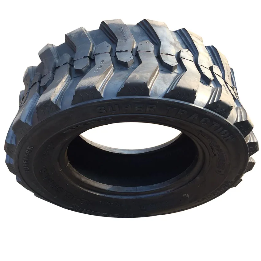 0Ah battery
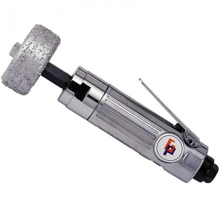 0 Battery (48-11-2420)
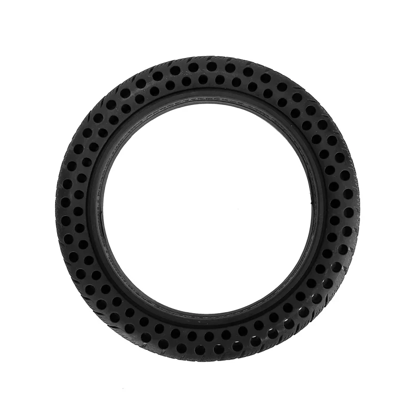 High speed tire buffers operate at speeds of up to 22,000 RPM and should not be used for flat repair applications due to risk of burning or scorching the tire.
 Milwaukee® warranty standards apply, including evaluation of wearable components and extreme use. This is higher than most pneumatic low speed tire buffers which typically only offer a 1-year warranty.
 Do not use adapter plugs with grounded power tools. Unmodified plugs and suitable outlets will reduce the risk of electric shock.
 Any power tool that cannot be operated with the switch is dangerous and must be repaired.
 Shorting the battery terminals together may cause burns or fire.
 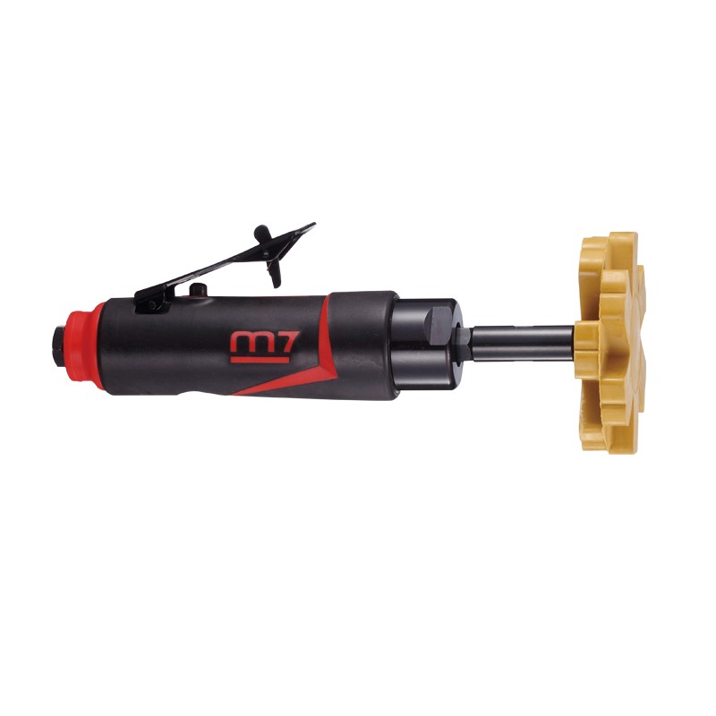 This will ensure the safety of the power tool.
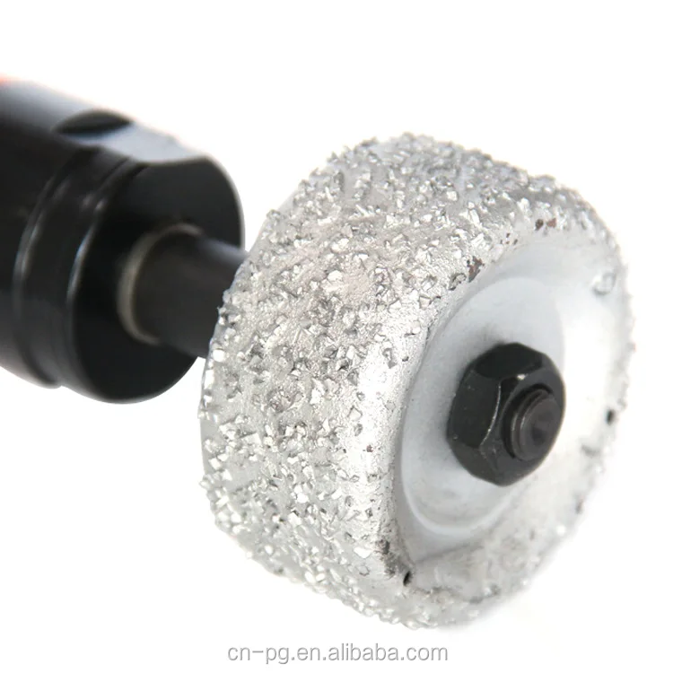
 Damaged accessories usually break during this test time.
 Accidental contact with a rotating accessory may catch on your clothing and pull the accessory into your body.
  The wheel may bounce towards or away from the operator, depending on the direction of travel of the wheel at the pinch point. Under these conditions, abrasive wheels can also break. Kickback is the result of power tool misuse and/or improper operating procedures or conditions and can be avoided by taking the proper precautions listed below.
  Feeding the tool in the wrong direction causes the drill tip to pop out of the work and pull the tool in the direction of that feed.
  It is impossible to foresee every situation that could lead to a dangerous outcome. Do not use this tool if you do not understand these operating instructions or if you feel that the operation is beyond your ability; contact MILWAUKEE® Tool or a trained professional for more information or training.
 ………………………………………………………….12 V DC
  To insert the battery, insert the block into the body of the tool. Make sure it is securely locked in place.
  Discard tips, cones, plugs, or wheels that have been dropped, rolled, bumped, subjected to extreme temperature changes, or come into contact with solvents or moisture.
 Press the mode select button down to select the drilling mode. mode. This application is used on the inside and outside of the tire.
  Designations of the main dimensions of the buffers "Megulastic" [58]
  Buffer loaded with a horizontal dynamic force [58]
  2 m / s (8 km / h) hits a stationary obstacle, the functioning of the steering device should not be impaired , brakes, drivetrain, suspension, fuel system, exhaust and cooling systems.
  The further the switch is pressed, the faster the speed.
  Never disassemble the tool, battery or charger. Contact a MILWAUKEE® Service Center for ALL repairs.
  Keep your pens clean, dry and free of grease. Use only mild soap and cloth for cleaning as some cleaners and solvents are harmful to plastic and other insulated parts. Some of these include gasoline, turpentine, lacquer thinner, paint thinner, chlorinated cleaning solvents, ammonia, and household cleaners containing ammonia. Never use flammable or combustible solvents near tools.
  Your satisfaction with our products is very important to us! If you experience any problems with the operation of this instrument, contact your authorized MILWAUKEE® dealer.
 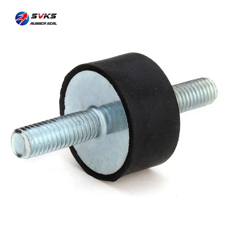 The rapid growth of deformations is accompanied by a gradually increasing load, and the rubber buffer becomes the stiffer, the more it is deformed.
 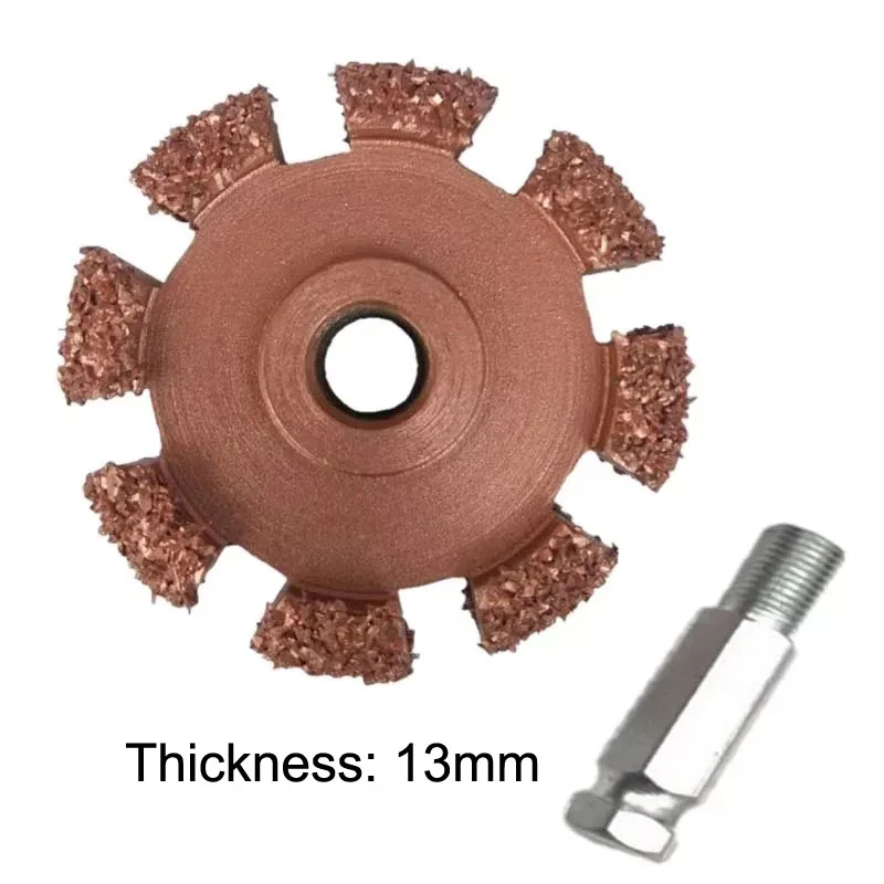 57; f d - deformation of the buffer during compression by force P d > given in Table 57. a is the correction factor for dynamic loads given in Table 58.
  3
3  5
5  8
8  5
5  8
8