Valve stems are a crucial part of any tire. Well, they are not part of a tire per se, but they are an auto part designed to ensure the tires’ safety and performance. Therefore, valves are important!
Valves keep air pressure from escaping tires. From valve cores to caps and versatile valve types, we will walk you through everything you need to know about valves and how said valves function.
The small tube system that you can use to fill your tires with air is called a valve stem. This system is basically a one-way door used to transfer gas (in this case air pressure) into a chamber (tire). Different valve types are available.
Valves are located on most pneumatic tires, from automobile to bicycle models. Tire valves are used to add or remove air pressure inside the tire. Once air pressure enters the tire, tire valves do not let it escape on their own.
A tire stem helps tires keep their optimal pressure levels, by using its different components. Valves consist of a valve stem body, a valve core, and a valve stem cap. These work together to keep the correct pressure levels inside the tires.
The various components of valves work together to enable the tire’s secure performance. Air pressure loss can occur if the valves are damaged. But, as long as they properly function, valves will hold air and guarantee the tires’ performance.
There are versatile types of tire valves available for purchase. The type you need greatly depends on various components: mainly what type of tire the valves are used on.
There are three different tire air valve stems manufactured:
These have various applications! Let’s talk about them in more detail.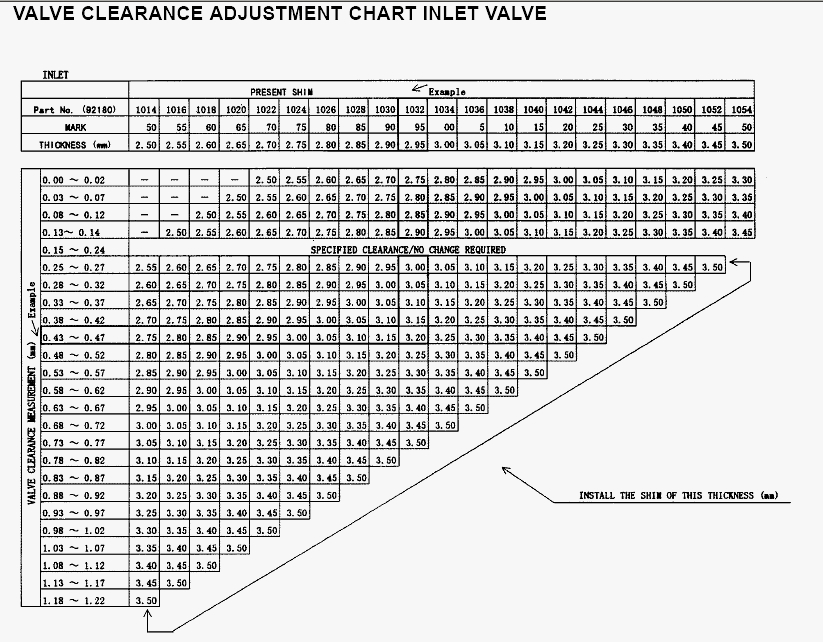
Probably the most common valve type is the tubeless rubber snap-in tire valve, as they are suitable for passenger cars, light-duty trailers, and various light trucks. Additionally, they can be used in autocross competitions as well.
These tire valves hold a maximum of 65 psi, as a cold tire inflation pressure. This valve stem size usually ranges between 0.7″ to 2.5″ and it can fit 0.453″ or 0.625″ diameter rim holes. Often they sport plastic valve stem covers, but some can be purchased with chrome sleeves or a metal tire pressure cap. However, this is merely for aesthetic purposes.
Check out this valve stem sizes chart:
The tubeless snap-in high-pressure tire valves function in the same manner as the previous type does. However, they are used for applications where the maximum pressure is above 65 psi. In other words, they are for medium- to heavy-duty trucks and trailers, that use pressure to handle larger weights.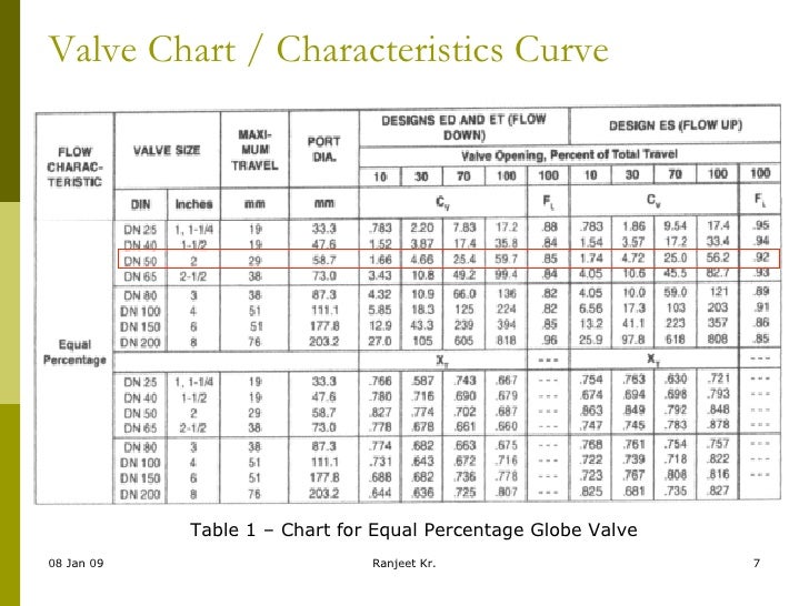
These tire valves are made in two rim hole fittings: 0.453″ for tires with a max cold inflation pressure of 80 psi, and 0.625″ for those with 100 psi. Due to the vehicle applications, these valve stem sizes range between 1.25″ to 2″. High-pressure valve stems are designed for steel wheels. They are equipped with thick rubber snap-in bases, metal barrels, and plastic pressure caps.
Size chart of high-pressure, tubeless snap-in valves:
High-pressure metal valve stems are clamp-in models that use a rubber grommet, which seals the valve against the wheel when you tighten the holding nut. These valves are generally manufactured for high speed, racing vehicles, or for vehicles exceeding 130 mph.
Most metal clamp-in tire valves are available for 0.453″ and 0.625″ rim holes. However, some special applications are available for 0.236″ and 0.315″ rim holes. Additionally, they come in straight or bent styles to accommodate even unique wheel shapes. These valves hold maximum cold tire inflation of 200 psi.
These valves have two fitting types: with the retaining (holding) nut inside or outside of the rim. For aesthetic reasons, many drivers prefer it to be hidden inside the rim. However, outer placements allow you to tighten the nut whenever it is necessary.
We have talked about the types of tire valves you can purchase for different vehicles. Now, let’s see their components.
Like most auto parts, valves also consist of multiple parts, which are:
These individual parts of valves work together to hold air in the tires. Some are crucial and some don’t have to be used. However, these parts working together will guarantee the vehicle’s secure drive.
A valve cap should be used on all valve stems. There is a good reason for this! Moisture contamination and loss of air pressure at high speeds can cause problems.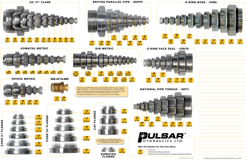 They can damage the valve core or cause the tire to do flat. However, a valve cap will help prevent these issues.
Tire valve caps are available to be manufactured from plastic, metal, or metal with a special screwdriver design. When these caps are used greatly depends on which vehicle they are on. When it comes to everyday driving, a plastic tire pressure valve cap should be enough. However, for racecar applications, a metal one is better. Tire stem caps are either knurled or hexagon-shaped to make them easier to remove.
While missing tire valve covers are not the end of the world, it is advisable to replace them. For one, it is a second seal that prevents pressure from escaping, in case valve core damage occurs. On the other hand, it also makes sure that sand, dirt, and moisture does not enter the stem and damage it.
A valve core is the main seal inside the stem. This part of the stem seals tire pressure inside the tire, preventing it from escaping. It should be tightly screwed into the valve core chamber. They are manufactured with shorter (for high speed applications) and longer lengths, and nickel-plated and brass valve cores are available.
It is important that you only use a nickel-plated valve core with an aluminum tire pressure sensor valve stem. This is due to brass valve cores in such applications experiencing corrosion that can transfer and affect the aluminum wheel as well. This is to protect the wheel and its integrity.
These valve cores basically consist of a spring-loaded pin that is moveable. This allows air pressure to inflate and deflate the tires. This valve stem seal prevents pressurized air from escaping the tires when the caps are off. The valve stem core is durable, but dirt, moisture, and sand can damage it. Dirt and sand will prevent valve cores from sealing properly, while moisture will freeze and damage the valve cores.
If you fit wheel covers on your car, you can use valve extensions to make the inflation process easier. These nylon or metal extenders are available in sizes between 0.5″ and 2″.
It is important to select the ideal extension length or to purchase durable, preferably metal, ones. Road and weather conditions and driving habits can easily damage these extensions, which will leave to other issues.
If your vehicle uses direct TPMS sensors, then the valve stems also hold the sensor inside the tire. Mechanics do this with metal clamp-in or rubber snap-in valves. These TPMS sensor tire valve stems work together to transmit information to the TPMS monitor.
The two different TPMS stem types function a bit differently. Let’s see how!
A clamp-in valve stem-sensor combination fits the sensor with a rubber seal and a retaining. These two parts, along with the valve cores and caps, need to be tightened correctly, in order to prevent pressure loss.
These TPMS rubber valves need nickel-plated valve cores to prevent damage. Galvanic corrosion can damage brass cores, which will transfer onto the aluminum barrel with time – leading to even bigger damage.
The other type of TPMS sensor tubeless tire valve is the rubber snap-in version. These accept TPMS sensors can be different, and purchasing valve stems that accommodate them in crucial.
If the TPMS stems are not compatible, it will lead to air pressure loss. Using the correct combination of valves and TPMS sensors will ensure a safer driving experience.
Have you ever noticed a vehicle with green valve stem caps?
Well, there is a reason for their distinct color! These valve stem seals keep the pressure inside of nitrogen-filled tires. Many believe that adding nitrogen in tires improves their performance, durability, fuel economy, etc.
Therefore, nitrogen valve stem caps are green!
Are Valve Stems Replaced with New Tires?
Usually, when mounting new tires on a vehicle, it is advisable to get new valve stems for tires as well.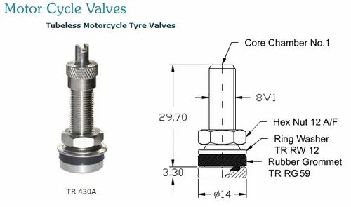 However, when you purchase new tires, the tire valve stem is not included.
The valve stem sizes you need depend on the rim size. Low-profile rims (up to 0.9″) will need a 1.5″ stem while a 1.3-1.7″ rim should have a 2.3″ valve stem. Anything taller than 1.9″ needs at least a 3.1″ valve stem to properly function.
To find a slow leak in a tire, you will needs a spray bottle and soapy water. Mix liquid soap and water in a spray bottle and spray the entire tire (sidewalls, tread area, along the rim, and the valve stem). The slow leak will be there the soapy water forms small bubbles with the escaping air.
Air pressure escapes the tire when the valves are open because of the different pressure levels inside the tire and in the atmosphere. The high pressure of the tire flows out until the tire features the atmospheric pressure. This causes the tire to go flat.
While there are three main types of tire valves: rubber snap-in, high-pressure snap-in, and high-pressure metal clamp-in; which type is appropriate for the application depends on the vehicle, required tire inflation pressures, driving circumstances, and wheel design. The Tire and Rim Association in the United States have given valve design numbers to different types and sizes of valves.
Valves can be installed in any position on the wheel, from horizontal to vertical, to match the wheel’s appearance. To accommodate valve-mounted tire pressure monitoring system transmitters, the most common valve alignment is almost horizontal, employed by many wheel manufacturers.
While tire valves can operate at any angle, valves mounted on a vertical axis and used at high speeds are more prone to lose pressure because of centripetal forces pushing the valve core and enabling air to escape. In our guide, you can find all valve stems the same size and which sized tire valve stem sizes fit your wheels.
By the end, you’ll see it’s much easier to get the right tire valve stems when you use a valve stem size chart. (Read Drywall Screw Sizes Chart)
It used to be that if the tubeless valve stem fit the hole in the wheel, it was the right one. This isn’t true, but it’s what they thought at the time. Today, that assumption could cause a lot of problems.
The tubeless valve stems that are in use today haven’t had many problems over the years. The huge popularity of tubeless tires today is proof that they work well and that the valve stems they need work well, too.
Increased inflation pressures and higher speed limits make selecting the proper valve stem extremely important.
Light truck owners have told the International Tire and Rubber Association (ITRA) that their tires suddenly lose air, sometimes when they’re going at a high rate of speed. It turns out that these people were using the wrong valve stems.
In light-duty trucks, most of the complaints are about snap-in valve stems on tires with ply ratings of up to 95 pounds per square inch. Most of the problems are with TR413 or TR15 series valve stems (6.6 bars).
These tires are now called medium- or even heavy-duty truck and bus tires because they have a lot of plys and are made out of steel. But because they can carry a lot of weight, some tires are still made in the sizes we used to think of as commercial light truck tires.
It’s sometimes the same size as the valve stem hole in a wheel for a passenger car. First, the TR413 series valve stems were designed to handle inflation pressures up to 60 pounds per square inch (4.1 bars).
However, they can only handle 65 psi (4.5 bars). Many old catalogs still in use say that the valve stems in the TR413 and TR415 series can only be used at 60 psi. This is not true.
One of the most likely problems you may encounter with the TR413 and TR415 series valve stems at any inflation pressure above 65 psi is the vale stem running at a higher than average temperature due to hot weather or other similar condition.
This can cause the valve stem to crack, blow out the rim hole, or become unseated.
In most cases, this can be fixed by replacing the old valve stem with a TR600HP or TR801HP high-pressure snap-in valve stem. These valve stems can handle up to 100 psi (6.9 bars). Another good idea is to use a metal valve stem that can be clamped in and has a 200 psi rating (13.8 bars).
The TR600HP and TR602HP valve stems have holes that are .453 inches wide. The TR801HP and TR802HP stems have holes that are .625 inches wide. (Learn How To Test Water Heater Element)
On wheels with stem holes that are more than .156 inches thick, the TR413 valve stem should not be used because it has a lower pressure.
The TR600HP high-pressure valve stems can only be used on wheels with a stem hole thickness of less than.205 inches. The TR602HP, TR801HP, and TR802HP valves all have the same tolerance.
Metal valve stems must be used when the rim thickness at the stem hole is more than .205 inches. If the area around the hole is coined meets the requirements, the wheel can be thicker. However, you should use the stem that fits the wheel’s stem hole.
Metal valve extensions should never be used with the TR600HP and TR801HP series snap-in valves as the centrifugal force generated at high speeds by the added weight of the metal extension can break or crack the stem, causing it to unseat and result in a loss of air.
This can probably occur even if the inflation pressure is within the limits of the snap-in valve stem.
Only plastic extensions should be used on snap-in valve stems from the TR600HP or TR801HP series, which have snap-in parts. If you have valve stems that can be clamped into place with metal, you only need extensions made of metal. The metal extensions should not be longer than is necessary.
If a car is going to be used both on and off the road, it’s always best to use clamp-in valve stems made of metal that are as short as possible.
A lubricant that isn’t made from petroleum should be used on all snap-in valve stems before they are put in the stem hole.
In addition, the stem hole should be checked to make sure there are no sharp edges or metal slivers that could damage the stem. There should also be no rust, excessive paint drippings, or other buildup on the valve stem seating area.
If you follow procedures according to industry standards and still have problems losing air through the stem hole, check the specifications for the stem hole in the wheel, including the prementioned thickness limitations.
It might not be big enough to machine or coin around the stem hole on some wheels with a.453-inch stem hole. On this type of wheel, the coined area must be at least.125 inches bigger than the valve hole.
The Tire and Rim Association Yearbook has all the information you need about specifications. You can also ask your suppliers for help.
Never assume that the stem on the tire/wheel assembly you’re working on for a customer is the right one, even if it looks like it. (Learn How To Clean Concrete Without Pressure Washer)
Someone who handled the tire/wheel assembly before you may have made a mistake or failed to fit the valve stem to the hole size, air pressure, or application. Installing the right stem can be as important as matching the wheel parts on a wheel with a lot of parts.
While there are no real standard sizes, here are some examples of valve stems you can find.
TR13
TR15
 618 and 0.633-inch rim hole.
TR 300
TR JS2
TR6
JS 89
Here are a few different varieties of valve stem types outside the above basic types.
Tubeless rubber snap-in valves have a maximum cold tire inflation pressure of 65 psi. They are suited for passenger cars, light-duty trailers, and light trucks, as well as autocross competition.
Rubber snap-in valves with effective lengths ranging from 7/8″ to 2-1/2″ accommodate either.453″ or.625″ diameter holes in the rim. (Find the Best Pressure Washer)
While most rubber snap-in valves have a plastic cover, some have chrome sleeves and metal caps to match the look of a custom or alloy wheels.
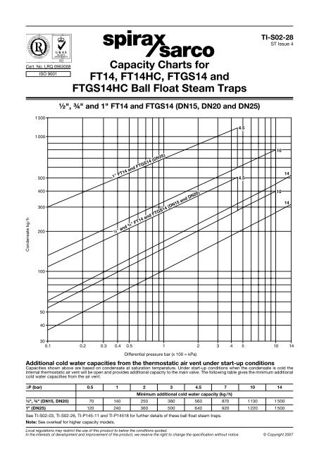
| Industry Valve Number | Max Inflation Pressure (PSI) | Effective Length (Inch) | Hole Diameter in Wheel (Inch) |
|---|---|---|---|
| 412 | 65 | 0.88 | 0.453 |
| 413 | 65 | 1.25 | 0.453 |
| 414 | 65 | 1.50 | 0.453 |
| 415 | 65 | 1.75 | 0.453 |
| 418 | 65 | 2.00 | 0.453 |
| 423 | 65 | 2.50 | 0.453 |
| 415 | 65 | 1.25 | 0.625 |
| 425 | 65 | 2.00 | 0.625 |
Tubeless high-pressure snap-in valves are designed for medium and heavy-duty trucks and trailers and must be used when the recommended cold tire inflation pressures exceed 65 psi.
The maximum cold inflation pressure for.453″ rim holes are 80 psi, whereas the maximum cold inflation pressure for. 625″ rim holes are 100 psi.
In steel wheels, high-pressure snap-in valves have a thicker rubber base with a metal barrel and a plastic cap. This type of valve is often found in these types of wheels. There are effective lengths that range from 1-1/4″ to 2″ long.
| Industry Valve Number | Max Inflation Pressure (PSI) | Effective Length (Inch) | Hole Diameter in Wheel (Inch) |
|---|---|---|---|
| 600HP | 80 | 1.27 | 0.453 |
| 602HP | 80 | 2.00 | 0.453 |
| 801HP | 100 | 1.31 | 0.625 |
| 802HP | 100 | 2.00 | 0.625 |
High-pressure metal clamp-in valves can be used with almost any wheel. They are recommended for all track activities and when the speed of the vehicle is going to be more than 130 mph.
When the retaining nut on metal clamp-in valves is tightened, a rubber grommet seals against the wheel.
While metal clamp-in valve design and styling can result in retaining nuts being hidden inside the wheel or visible outside, those with the retaining nut on the outside have the advantage of examining and modifying retaining nut tightness without having to remove the tire from the wheel.
Metal clamp-in valves have a maximum operating pressure of 200 psi and are available in rim sizes 0.453″ or 0.625″, as well as custom sizes like 6mm (.236″) or 8mm (.315″).
In addition, metal clamp-in valves have a metal cap available in straight or bent configurations to fit wheels with unusual forms.
They have effective lengths ranging from flush to 2″ and in straight or bent configurations to fit wheels with unique geometries. For racing applications, low-profile and lightweight alloy clamp-in valves are also available.
Regardless of valve type, the valve core is the primary sealing component and should be fitted snugly into the valve core chamber.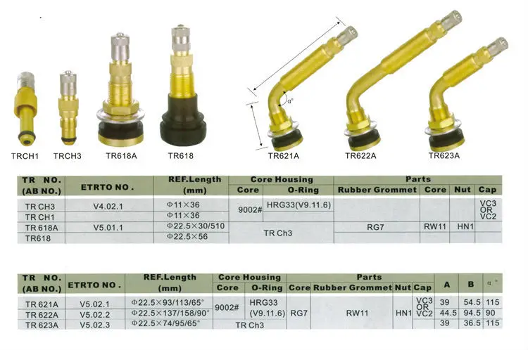 Valve cores are available in two lengths: short and long, with the latter being favored for high-performance applications.
Valve cores are offered in nickel-plated and brass finishes. A valve stem will experience galvanic corrosion if a standard brass valve core is used in aluminum; the brass valve core will eventually seize in the valve’s aluminum barrel.
Nickel-plated valve cores must instead of brass valve cores in the aluminum valve stems of tire pressure monitoring sensors to help avoid galvanic corrosion.
When inflating a tire, all valve cores have a seal coupled to a moveable, spring-loaded pin that permits pressurized air to flow while allowing air to escape when the pin is depressed to unseat the seal.
While valve cores can withstand a working pressure of 300 psi, grit, sand, and moisture must be avoided. Grit and sand may prevent valve cores from properly closing, and moisture can freeze and undermine the seal in freezing conditions.
Valve caps should always be used for various reasons, including high-speed pressure loss and core contamination.
If the cap on tire valve is compromised, the valve cap acts as a backup seal, preventing air from escaping.
While utilizing valve caps may make checking tire pressures in the pits at a racetrack take longer, the consequences of a tire losing pressure are far harsher.
Valve caps come in three different types: plastic dome, metal dome, and a metal “screwdriver” design for tightening and loosening valve cores.
If you want to drive on the racetrack, you’ll need metal valve caps instead of plastic dome caps. This is because racetracks can get very hot, and plastic dome caps can’t handle that.
Valve caps are knurled to make tightening and loosening easier, and some metal caps include hex head designs. To completely seal the valve, metal caps utilize a rubber washer or o-ring.
If the cap on the tire valve cap is missing, squeeze the valve core briefly to release a small amount of air before monitoring or adding air pressure. This will allow debris to be blown out of the valve by the pressurized air inside the tire.
It’s more challenging to avoid wetness because it’s sometimes difficult to get a steady dry air source. Therefore, checking or adding tire inflation pressure outside during a blizzard is not suggested unless required.
Vehicles with wheel covers may also use nylon or metal extensions ranging in length from 1/2″ to 2″ to facilitate checking and adjusting tire pressures easier.
Mud, ice, and snow have packed into the tips of the nylon extensions and enable air to escape because they are exposed to the weather.
If the nylon extensions scrape against a curb, the damaged tip can depress the valve core, escaping air. Ideally, tire valves of adequate length or metal extensions threaded to take a valve cap should be used.
Tire valves should be inspected and changed if any cracking emerges. Rubber deteriorates with time, and tire valves are not intended to resist degradation throughout the life of two standard tires in typical service.
According to industry standards, tire valves should be replaced whenever new tires are mounted.
While Track & Competition DOT tires may only last a few weekends, the metal clamp-in tire valves should be replaced every other year.
Heat delivered to the wheels from the brakes is much higher than in everyday use, and even any valve type could suffer.
Even if you have these on a light-duty trailer, even if the inner tube or tire is fine, the tire valve could degrade because of the weather no matter how much you use your trailer.
Metal clamps or rubber snap-in valves are used to hold sensors and transmitters in place in many direct tire pressure monitoring systems (TPMS).
The threaded insert at the base of these distinctive metal clamp-in valves accepts the bolt that connects the sensor/transmitter to the valve.
Quick Jump Items
The air vent valve is a device for the ventilation systems, which is used to regulate and control the air flow. Throttling valves are used to control the airflow rate in the ventilation system using a manual or automatic actuator (electric or pneumatic).
Externally, the damper is a metal case made for a certain size of the air duct, inside which there is a blade fixed on an axis and driven by a lever or an electric drive.
Air damper actuator catalog Air damper and valve catalog
Selecting the appropriate actuator for a particular air valve requires consideration and consideration of a number of factors:
If the air damper needs to be fixed in one position after initial adjustment (e.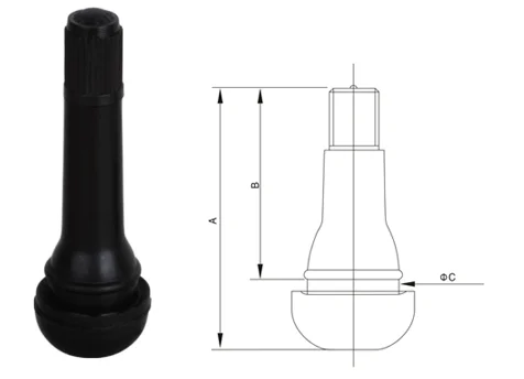 g. balancing damper) or if its position only needs to be changed a couple of times a year (e.g. for summer/winter changeover), a manual actuator may be engaged. drive. If the damper is required for automatic operation as part of a ventilation and air conditioning system, an electric or pneumatic actuator must be provided.
In the following, we will only consider direct connected electric drives.
Electric actuators for air valves of ventilation systems are divided by:
air valve actuators have two main divisions: spring return actuators and non spring return actuators .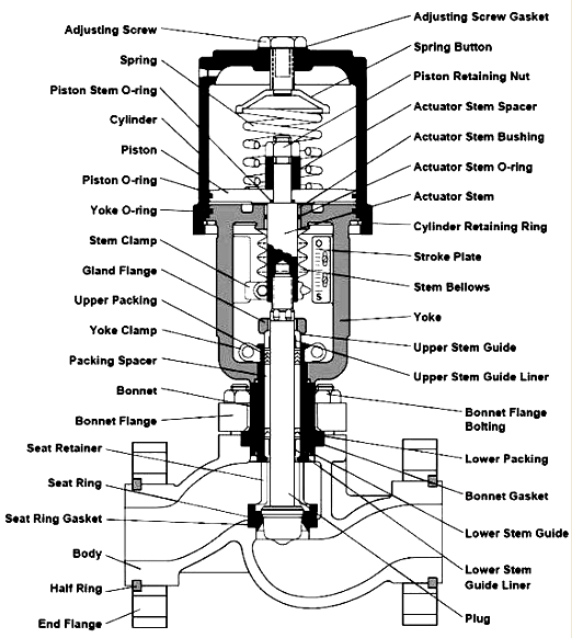
Spring return actuators are designed for HVAC applications. They perform security functions, are designed, for example, to protect against freezing, smoke. When the air damper of the valve is moved to its normal operating position, the return spring is charged in the electric actuator, when the power supply is interrupted, the energy stored in the spring returns the damper to the protective position.
Electric actuators without spring return are designed to control air dampers in building ventilation and air conditioning systems. In these actuators, the spring, when the power supply is interrupted, retains the specified position.
If you want the air damper to move to the safety position when the power supply to the actuator fails, select spring return actuator .
How the built-in return spring works - simultaneously with
turning the air damper to the normal position, the return spring
is cocked. In the event of a power failure, the damper automatically returns to the guard position
due to the energy of the spring. Spring actuators
can be used, for example, on outside air dampers
to protect water heat exchangers from freezing.
These servo drives have three types of control signal: two-position, three-point and modulating (0…10Vdc).
If it is necessary that the air damper remains in its original position when the power supply to the actuator is interrupted, select actuator without return spring .
Actuators without built-in return spring remain in the same position when the supply voltage is switched off.
These servo drives have three types of control signal: two-position, three-point and modulating (0…10Vdc).
In the photo above you can compare models from Dastech and Belimo with the same torque. The difference between the model with a return spring is not only in control, but also in overall dimensions - they are larger. The case of electric actuators without a spring, as a rule, is made of plastic and they are noticeably lighter. But models with a spring return work faster, the AR-05N24S damper turn time is 70/20 seconds, while the LM24A-S has 150 seconds. in both directions.
Lack of spring return allows to produce ventilation actuators with minimal dimensions and reduces their cost.
two-position electric actuators (open/closed control) are controlled by power on or power off. Turning on the power starts the actuator and brings it to the set operating position. Removing power allows the actuator spring to return the air damper to its original position, depending on whether it is "normally closed" or "normally open".
Three-point control (pulse control) - the stem moves by an amount proportional to the duration of the supply signal. With three-point control, the position of the stem does not depend on the voltage and the actuator receives an opening or closing signal. In the case of three-point control, the magnitude of the control signal is constant, but it comes through different channels. When one contact closes, the drive opens (or closes), when the second contact closes, the drive closes (or opens). If power is not supplied to either the first or the second, the drive stops. Thus, by applying a sequence of pulses / pauses to the appropriate contacts, the actuator can be moved to any position.
Analog control (proportional) - stem moves by an amount proportional to the control signal (voltage or current). With analog control (direct), the position of the electric actuator stem depends on the magnitude of the applied voltage in the range from 0 to 10V (2-10V). For example, if the controller has determined that a control valve controlled by an electric drive should be half open, then it sends an analog control signal with a nominal value of 5 Volts, if the valve should be fully opened, then a control signal of 10V should be generated.
Having decided on the type of control, select the drive torque.
Actuator closing force is measured in Newtons per meter (Nm). The magnitude of the force determines which valve and at what pressure drop the actuator can close. The required force for closing is specified in the characteristics of the control valve.
The actual torque required to operate the valve depends on a number of factors:
How the damper is installed in the duct and how the actuator is installed can greatly affect torque requirements. Valves installed with a skewed square profile (losing the correct rectangular shape) can require many times more torque than dampers installed evenly and correctly.
Always select a valve actuator with a rated torque greater than the desired damper torque. When choosing an actuator that will use a lever arrangement rather than the preferred "straight" connection, it is recommended to consider an additional safety factor (margin) of 30 to 50%. When in doubt, the next larger drive is always the safest choice.
| Torque table depending on valve size | ||||||||||||||
|---|---|---|---|---|---|---|---|---|---|---|---|---|---|---|
| Air valve cross section, mm | 200 | 250 | 300 | 400 | 500 | 600 | 700 | 800 | 1000 | 1200 | 1400 | 1600 | 1800 | 2000 |
| 200 | 3 Nm | 3 Nm | 3 Nm | 3 Nm | 3 Nm | 3 Nm | 3 Nm | 3 Nm | 3 Nm | 5 Nm | 5 Nm | 5 Nm | 5 Nm | 5 Nm |
| 250 | 3 Nm | 3 Nm | 3 Nm | 3 Nm | 3 Nm | 3 Nm | 3 Nm | 3 Nm | 5 Nm | 5 Nm | 5 Nm | 5 Nm | 8 Nm | 8 Nm |
| 300 | 3 Nm | 3 Nm | 3 Nm | 3 Nm | 3 Nm | 3 Nm | 5 Nm | 5 Nm | 5 Nm | 5 Nm | 8 Nm | 8 Nm | 8 Nm | 8 Nm |
| 400 | 3 Nm | 3 Nm | 3 Nm | 3 Nm | 3 Nm | 5 Nm | 5 Nm | 5 Nm | 5 Nm | 8 Nm | 8 Nm | 8 Nm | 8 Nm | 8 Nm |
| 500 | 3 Nm | 3 Nm | 3 Nm | 3 Nm | 5 Nm | 5 Nm | 5 Nm | 5 Nm | 8 Nm | 8 Nm | 8 Nm | 8 Nm | 10 Nm | 10 Nm |
| 600 | 3 Nm | 3 Nm | 3 Nm | 5 Nm | 5 Nm | 5 Nm | 8 Nm | 8 Nm | 8 Nm | 8 Nm | 10 Nm | 10 Nm | 10 Nm | 10 Nm |
| 700 | 3 Nm | 3 Nm | 5 Nm | 5 Nm | 5 Nm | 8 Nm | 8 Nm | 8 Nm | 8 Nm | 10 Nm | 10 Nm | 10 Nm | 20 Nm | 20 Nm |
| 800 | 3 Nm | 3 Nm | 5 Nm | 5 Nm | 5 Nm | 8 Nm | 8 Nm | 8 Nm | 8 Nm | 10 Nm | 10 Nm | 20 Nm | 20 Nm | 20 Nm |
| 1000 | 3 Nm | 5 Nm | 5 Nm | 5 Nm | 8 Nm | 8 Nm | 8 Nm | 8 Nm | 10 Nm | 10 Nm | 20 Nm | 20 Nm | 20 Nm | 20 Nm |
| 1200 | 5 Nm | 5 Nm | 5 Nm | 8 Nm | 8 Nm | 8 Nm | 10 Nm | 10 Nm | 10 Nm | 20 Nm | 20 Nm | 20 Nm | 20 Nm | 20 Nm |
| 1400 | 5 Nm | 5 Nm | 8 Nm | 8 Nm | 8 Nm | 10 Nm | 10 Nm | 10 Nm | 20 Nm | 20 Nm | 20 Nm | 20 Nm | 20 Nm | 20 Nm |
| 1600 | 5 Nm | 5 Nm | 8 Nm | 8 Nm | 8 Nm | 10 Nm | 10 Nm | 20 Nm | 20 Nm | 20 Nm | 20 Nm | 20 Nm | 30 Nm | 30 Nm |
| 1800 | 5 Nm | 8 Nm | 8 Nm | 8 Nm | 10 Nm | 10 Nm | 20 Nm | 20 Nm | 20 Nm | 20 Nm | 20 Nm | 30 Nm | 30 Nm | 30 Nm |
| 2000 | 5 Nm | 8 Nm | 8 Nm | 8 Nm | 10 Nm | 10 Nm | 20 Nm | 20 Nm | 20 Nm | 20 Nm | 20 Nm | 30 Nm | 30 Nm | 30 Nm |
| Torque table depending on damper section | ||||||
|---|---|---|---|---|---|---|
| Shutter size | 100 mm | 125 mm | 160 mm | 200 mm | 250 mm | 315 mm |
| Section area | 0. 008 m² 008 m² | 0.012 m² | 0.02 m² | 0.03 m² | 0.05 m² | 0.08 m² |
| Actuator force | 2 Nm | 2 Nm | 3 Nm | 3 Nm | 3 Nm | 3 Nm |
| Example | DA-02N24 | Dastech DA-04N220 | ||||
| Shutter size | 355 mm | 400 mm | 500 mm | 630 mm | 800 mm | 1000 mm |
| Section area | 0.1 m² | 0.13 m² | 0.2 m² | 0.31 m² | 0.5 m² | 0.79 m² |
| Actuator force | 3 Nm | 4 Nm | 5 Nm | 6 Nm | 8 Nm | 16 Nm |
| Torque table depending on damper area | ||
|---|---|---|
| Force | Gate area up to | Electric drive example |
| 2 Nm | 0. 4 m2 4 m2 | Belimo CM24-SR-R (2Nm/24V) |
| 2.5 Nm | 0.5 m2 | Belimo TF230 (2.5Nm/230V) |
| 3 Nm | 0.6 m2 | Belimo LU230A (3Nm/230V) |
| 4 Nm | 0.8 m2 | Belimo LF24 (4Nm/24V) |
| 5 Nm | 1 m2 | Belimo LM24A (5Nm/24V) |
| 7 Nm | 1.5 m2 | Siemens GMA121.1E (7Nm/24V) |
| 8 Nm | 1.5 m2 | Lufberg DA08N24 (8Nm/24V) |
| 10 Nm | 2 m2 | Belimo NF230A (10Nm/230V) |
| 15 Nm | 3 m2 | Siemens GEB331.1E (15Nm/230V) |
| 16 Nm | 3 m2 | Lufberg DA16N220 (16Nm/230V) |
| 18 Nm | 3.5 m2 | Siemens GCA321.1E (18Nm/230V) |
| 20 Nm | 4 m2 | Belimo SM230A (20Nm/230V) |
| 24 Nm | 4. 5 m2 5 m2 | Lufberg DA24N220S (20Nm/230V) |
| 25 Nm | 4.5 m2 | Siemens GBB331.1E (25Nm/230V) |
| 30 Nm | 6 m2 | Belimo EF230A (30Nm/230V) |
| 32 Nm | 6 m2 | Lufberg DA32N220 (32Nm/230V) |
| 35 Nm | 7 m2 | Siemens GIB331.1E (35Nm/230V) |
| 40 Nm | 8 m2 | Belimo GM230AE (40Nm/230V) |
Important! The data given in the table are indicative. It is worth remembering that air valves with high tightness require more effort to regulate the air damper. The pressure and speed of the air flow in the ventilation system also have a strong influence. Therefore, in any case, it is recommended to buy an electric drive with a margin.
Manufacturers of servo drives indicate the recommended air damper area in the passport, however, the recommendations can vary greatly, so Belimo for the NM230A-S model (10Nm / 230V) indicates a damper up to 2m², but Siemens for a similar model GLB336. 1E (10Nm / 230V ) indicates a smaller area - up to 1.5m².
It should be remembered that dampers with an area of three or more square meters are often structurally made with two or more stems. The lamellae associated with them are independent. In this case, several drives with less effort are installed.
The supply voltage of the electric drive must correspond to the supply voltage of the control controller, for example, to a controller powered by a 24V mains voltage, only an electric drive powered by 24V can be connected. Most servos are available in 24V or 230V. Accordingly, the choice is limited to only two options.
Actuators can be produced with additional switches that perform additional functions, are designed to signal the end positions or perform a switching function at any position of the damper. The switching points for switches A and B (one for each) can be set independently from each other in the range 0–90° in steps of 5°.
Actuator stroke, measured in millimeters, corresponds to the distance between the maximum down stroke and the maximum up stroke. The stroke of the electric actuator must be greater than or equal to the stroke of the control valve.
Actuator speed, measured in sec/mm, corresponds to the time in seconds required to move the stem by 1 millimeter.
Maximum fluid temperature at which an electric actuator can be used. The electric drive itself does not come into contact with the coolant, but the heat from the coolant is transferred through the valve stem to the electric drive stem. If the operating temperature is higher than the maximum temperature, rod coolers should be used.
Electrical connection of air actuator without return spring with 2/3 position and modulating control for 24V and 220V
Electrical connection for spring return air actuator with 2-position and modulating control for 24V and 220V. Wiring diagram for auxiliary switches (for 1 SPDT and 2 SPDT)
Question. Can fire damper actuator be used?
Reply. Yes you can. The principle of operation of the OZK electric drive is similar to servo drives installed on ventilation dampers.
Question. What is the difference between an air drive and a fire engine?
Answer. The principle of operation is the same, but there are differences in the materials used. For example: Belimo firefighters use a body made of fire-resistant non-flammable plastic or metal, bushings and a gearbox are made of metal. Those. fire servomotors comply with fire safety requirements (applied to OZK dampers), but air ones do not.
There is also a difference in the transmission link for installation on the shaft. For firefighters, it is mainly designed for a square shaft 12x12 mm, and for ventilation, a universal grip is used that fits both round and square shafts of different sizes.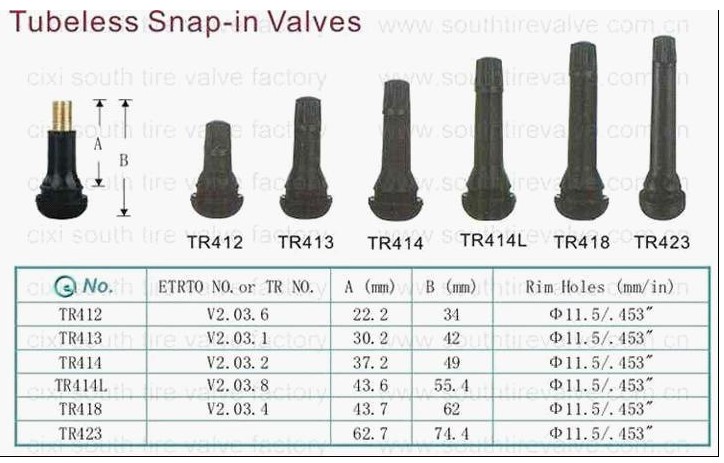
Question. Are there spring return actuators with smooth control?
Answer. Available, but not available from all manufacturers. For example, Belimo and Lufberg have it, but Nanotek doesn't.
If you find it difficult to choose the right electric drive for the ventilation damper, you can contact Panoramavent managers for advice. Experienced employees of our company will try to find for you the drive that you need.
The main parameters and dimensions of the valves comply with the standards specified in Table 1.
Table 1
| Name of the main parameters and dimensions | Values by type or version | |||
|---|---|---|---|---|
PKK-40MN-0. 6(F) 6(F) | PKK-40MS-0.6(F) | PKK-40MN-1.6(F) | PKK-40MS-1.6(F) | |
| 1 Nominal diameter DN, mm: — coupling — flanged | 40 50 | 40 50 | 40 50 | 40 50 |
| Name of main parameters and dimensions | Values by type or version | |||
| PKK-40MN-0.6(F) | PKK-40MS-0.6(F) | PKK-40MN-1.6(F) | PKK-40MS-1.6(F) | |
| 2 Maximum inlet pressure, MPa (kgf/cm²) | 0.6(6) | 0.6(6) | 1.6(16) | 1.6(16) |
| 3 Controlled pressure regulation limits: | ||||
| a) with low pressure spring, MPa (kgf/cm²) | 0. 0015…0.005 0015…0.005 (0.015…0.05) | 0.0015…0.005 (0.015…0.05) | ||
| b) with medium pressure spring, MPa (kgf/cm²) | 0.005…0.06 (0.05…0.6) | 0.005…0.06 (0.05…0.6) | ||
| 4 The lowest inlet pressure at which the main valve closes, MPa (kgf/cm²): | ||||
| - when operating on natural gas, MPa (kgf / cm²): | 0.01…0.015 (0.1…0.15) | |||
| - when operating on liquefied gas, MPa (kgf / cm²) | 0.03…0.05 (0.3…0.5) | |||
| 5 Seal class | A according to GOST 9544-2005 | |||
| 6 Connecting dimensions: | ||||
| - socket - inlet and outlet internal thread | G 1½ | |||
| - flanged | GOST 12815-80 isp. 1 per Ru=1.6 MPa 1 per Ru=1.6 MPa | |||
| Overall dimensions, mm, no more, coupling (flanged) | ||||
| length | 177 (180) | |||
| width | 124 (125) | |||
| height | 252 (268) | |||
| 7 Face-to-face, mm, socket (flanged) | 170 (180) | |||
| 8 Coupling (flanged) weight, kg, not more than | 4.7 (6.1) | |||
MTBF at least 4000 hours.
Average service life, years, not less than – 15.
Assigned service life, years, not less than – 40.
; 2 - main valve; 3 – membrane box; 4 - check valve; 5 - top valve; 6 - cover; 7 - adjusting glass; 8 - spring; 9 - membranes; 10 - starting plug; 12 - filter
Safety shut-off valve PKK-40M consists of a body (see pictures), a main valve, a membrane box, a check valve with a filter, a top valve, a cover, an adjusting cup, a spring, two membranes and a starting plug .
The valve has a socket or flanged valve body with integral seat. On the upper flange of the housing there is a membrane box, on top of which there is a cover with an adjusting cup and a spring. Lower and upper membranes are inserted between the ends of the body, box and cover and are clamped with bolts.
Inside the body there is a main valve with a spring that covers the seat. The upper threaded part of the valve stem is connected to the lower diaphragm. The end of the rod is the saddle. There are two mutually perpendicular holes in the rod connecting the cavities of the housing and the membrane chamber. A small (upper) valve is fixed in the upper membrane. A starting plug and a check valve are screwed into the threaded holes of the membrane box.
When slowly opening the inlet valve, the valve jump is not allowed, the gas fills the cavity under the membrane and fills the space between the membranes through two mutually perpendicular holes in the stem.
The start plug must be unscrewed to open the valve. In this case, the gas between the membranes will quickly escape into the atmosphere through the holes in the plug.
The inlet gas pressure, overcoming the force of the main valve spring, will lift the lower diaphragm up to the stop, and the hole at the end of the stem will be closed by the small valve of the upper diaphragm. After that, the starting plug is screwed back.
Gas enters the network through the open main valve and from the controlled area, through the impulse tube, through the check valve enters the cavity between the membranes.
If the controlled gas pressure exceeds the value set by the upper spring, the upper diaphragm will rise, the hole on the stem will open, and the same inlet gas pressure will be established on both sides of the lower diaphragm.
Under the action of the spring, the main valve is lowered onto the seat, shutting off the gas supply, and due to the closing of the check valve, the communication between the cavity of the membrane chamber and the impulse line will stop.