Currency USD
Skip to Content
Compare Products
Currency USD
Fitment CategoryPassengerATV
Year20232022202120202019201820172016201520142013201220112010200920082007200620052004200320022001200019991998199719961995199419931992199119901989198819871986198519841983198219811980197919781977197619751974197319721971197019691968196719661965196419631962196119601959
Make-
Model-
SubModel-
Year202120202019201820172016201520142013201220112010200920082007200620052004200320022001200019991998199719961995199419931992199119901989198819871986198519841983198219811980197919781977197619751974197319721971
Make-
Model-
SubModel-
View as Grid List
10 Items
Show
122436All
per page
Sort By PositionProduct NamePriceInnerMasterFrequencyCenter BoreMakeLengthSet Descending Direction
View as Grid List
10 Items
Show
122436All
per page
Sort By PositionProduct NamePriceInnerMasterFrequencyCenter BoreMakeLengthSet Descending Direction
TPMS Valve Stems are available in Snap In and Metal Bolt In configurations. TPMS Valve Stems are constructed of the same materials as Snap In and Metal Bolt In valve stems and available in different configurations for that specific application or sensor type. TPMS Valve Stems and rubber components are made with 30% EPDM rubber molding. EPDM, (ethylene propylene diene monomer) is a type of synthetic rubber that exhibits resistance to hydraulic fluids, similar to the characteristics of brake fluid, and outstanding resistance to heat, ozone, and weather. All our valve stem assemblies offered are manufactured to SAE requirements.
| Regardless of the valve type, the valve core is the fundamental sealing device and should be snugly screwed into the valve core chamber. Valve cores come in short and long lengths, with the short length being preferred for high performance applications. Valve cores are available in both nickel-plated and brass. The nickel-plated valve core is used in aluminum valve stems of tire pressure monitoring sensors because using a standard brass valve core in an aluminum tire pressure sensor valve stem will experience galvanic corrosion* and the brass valve core will eventually seize in the valve's aluminum barrel. All valve cores feature a seal attached to a movable, spring-loaded pin that allows pressurized air to pass when inflating a tire, or to allow air to escape when the pin is depressed to unseat the seal. Valve cores have a working pressure of 300 psi. It is important to protect them from grit, sand and moisture. Grit and sand might prevent valve cores from sealing completely, and moisture can freeze in cold temperatures and defeat the seal. |
Valve Caps
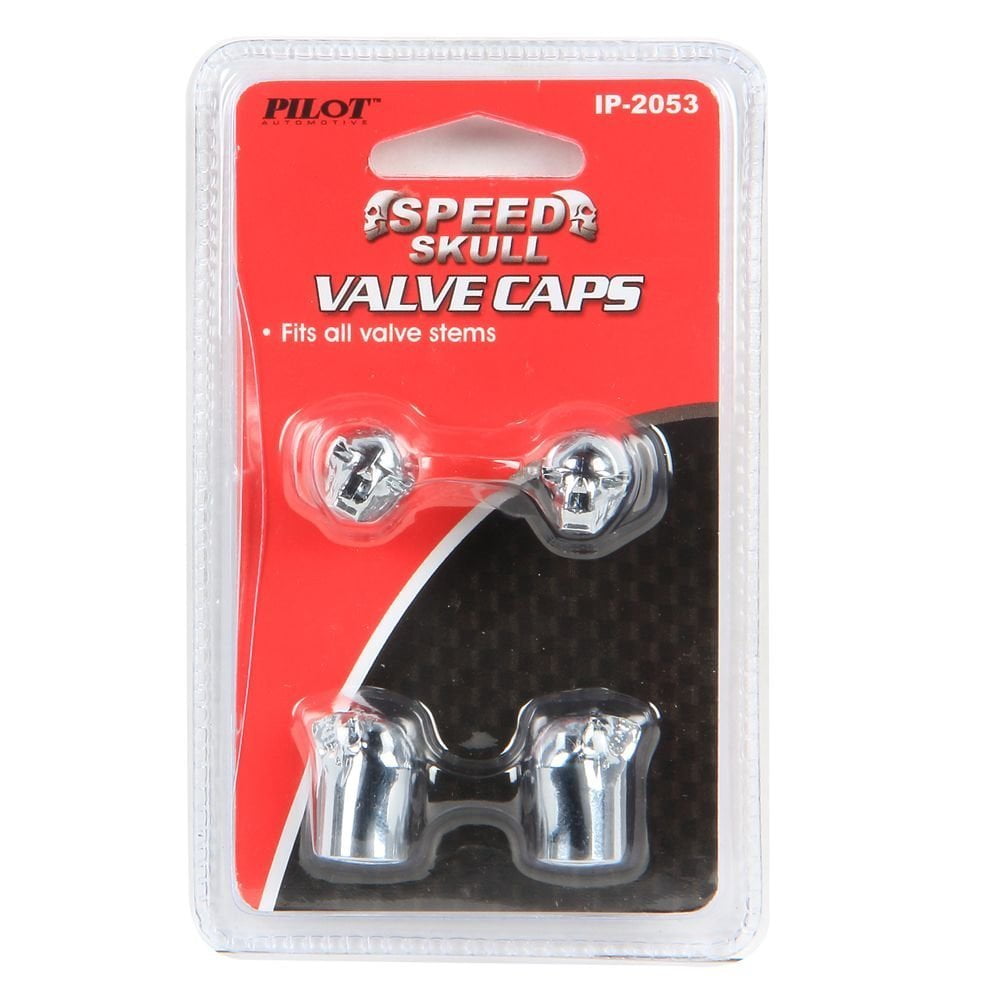
Valve Caps are available in plastic and metal. The plastic caps are fine for normal driving whereas metal valve caps to designed to withstand the high temperatures applications. Valve caps are knurled to make it easier to tighten or loosen them, while some metal caps feature hex head designs tools are available for easier removal and installation. Valve caps use a rubber washer or o-ring to seal the valve completely.
High-speed pressure loss and core contamination are reasons why valve caps should always be used.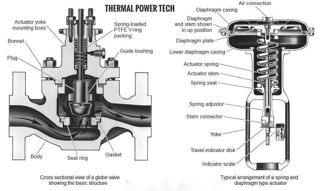 In the event anything disrupts the valve core's seal, the valve cap provides a backup seal that prevents air from escaping.
Shop By
Shopping Options
Valve Stem Length
Valve stems are a crucial part of any tire. Well, they are not part of a tire per se, but they are an auto part designed to ensure the tires’ safety and performance. Therefore, valves are important!
Valves keep air pressure from escaping tires. From valve cores to caps and versatile valve types, we will walk you through everything you need to know about valves and how said valves function.
The small tube system that you can use to fill your tires with air is called a valve stem. This system is basically a one-way door used to transfer gas (in this case air pressure) into a chamber (tire).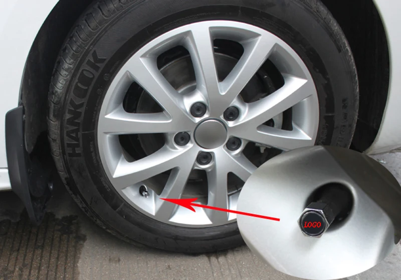 Different valve types are available.
Valves are located on most pneumatic tires, from automobile to bicycle models. Tire valves are used to add or remove air pressure inside the tire. Once air pressure enters the tire, tire valves do not let it escape on their own.
A tire stem helps tires keep their optimal pressure levels, by using its different components. Valves consist of a valve stem body, a valve core, and a valve stem cap. These work together to keep the correct pressure levels inside the tires.
The various components of valves work together to enable the tire’s secure performance. Air pressure loss can occur if the valves are damaged. But, as long as they properly function, valves will hold air and guarantee the tires’ performance.
There are versatile types of tire valves available for purchase. The type you need greatly depends on various components: mainly what type of tire the valves are used on.
There are three different tire air valve stems manufactured:
These have various applications! Let’s talk about them in more detail.
Probably the most common valve type is the tubeless rubber snap-in tire valve, as they are suitable for passenger cars, light-duty trailers, and various light trucks. Additionally, they can be used in autocross competitions as well.
These tire valves hold a maximum of 65 psi, as a cold tire inflation pressure. This valve stem size usually ranges between 0.7″ to 2.5″ and it can fit 0.453″ or 0.625″ diameter rim holes. Often they sport plastic valve stem covers, but some can be purchased with chrome sleeves or a metal tire pressure cap. However, this is merely for aesthetic purposes.
Check out this valve stem sizes chart:
The tubeless snap-in high-pressure tire valves function in the same manner as the previous type does.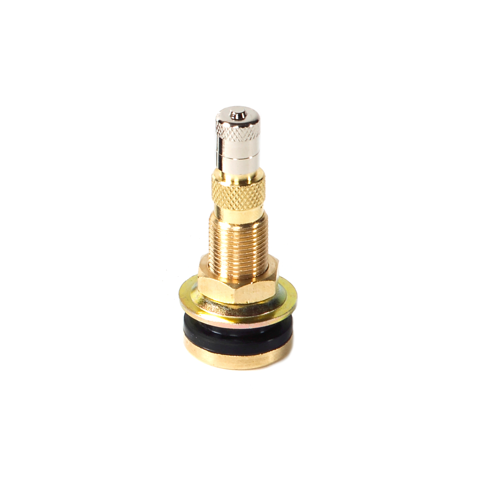 However, they are used for applications where the maximum pressure is above 65 psi. In other words, they are for medium- to heavy-duty trucks and trailers, that use pressure to handle larger weights.
These tire valves are made in two rim hole fittings: 0.453″ for tires with a max cold inflation pressure of 80 psi, and 0.625″ for those with 100 psi. Due to the vehicle applications, these valve stem sizes range between 1.25″ to 2″. High-pressure valve stems are designed for steel wheels. They are equipped with thick rubber snap-in bases, metal barrels, and plastic pressure caps.
Size chart of high-pressure, tubeless snap-in valves:
High-pressure metal valve stems are clamp-in models that use a rubber grommet, which seals the valve against the wheel when you tighten the holding nut. These valves are generally manufactured for high speed, racing vehicles, or for vehicles exceeding 130 mph.
Most metal clamp-in tire valves are available for 0.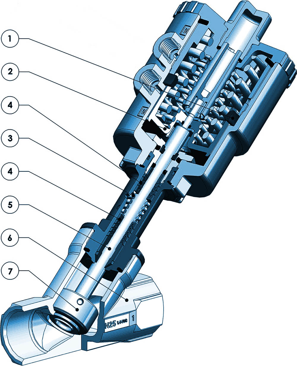 453″ and 0.625″ rim holes. However, some special applications are available for 0.236″ and 0.315″ rim holes. Additionally, they come in straight or bent styles to accommodate even unique wheel shapes. These valves hold maximum cold tire inflation of 200 psi.
These valves have two fitting types: with the retaining (holding) nut inside or outside of the rim. For aesthetic reasons, many drivers prefer it to be hidden inside the rim. However, outer placements allow you to tighten the nut whenever it is necessary.
We have talked about the types of tire valves you can purchase for different vehicles. Now, let’s see their components.
Like most auto parts, valves also consist of multiple parts, which are:
These individual parts of valves work together to hold air in the tires. Some are crucial and some don’t have to be used. However, these parts working together will guarantee the vehicle’s secure drive.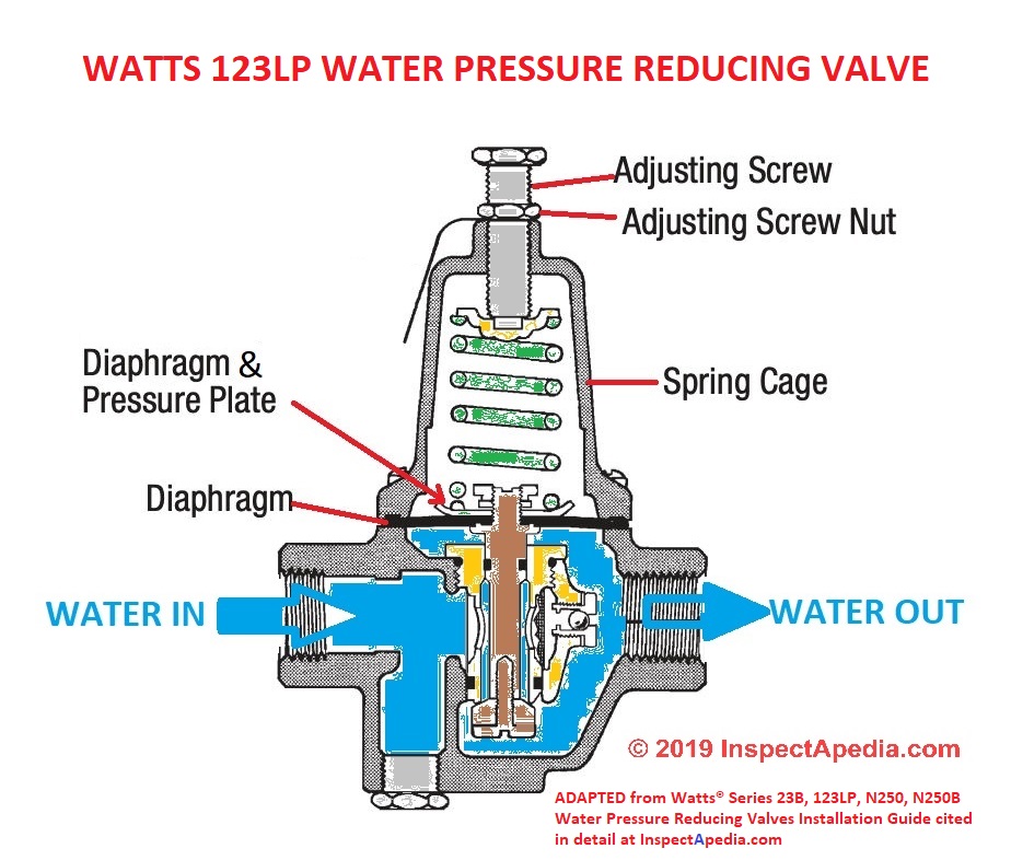
A valve cap should be used on all valve stems. There is a good reason for this! Moisture contamination and loss of air pressure at high speeds can cause problems. They can damage the valve core or cause the tire to do flat. However, a valve cap will help prevent these issues.
Tire valve caps are available to be manufactured from plastic, metal, or metal with a special screwdriver design. When these caps are used greatly depends on which vehicle they are on. When it comes to everyday driving, a plastic tire pressure valve cap should be enough. However, for racecar applications, a metal one is better. Tire stem caps are either knurled or hexagon-shaped to make them easier to remove.
While missing tire valve covers are not the end of the world, it is advisable to replace them. For one, it is a second seal that prevents pressure from escaping, in case valve core damage occurs. On the other hand, it also makes sure that sand, dirt, and moisture does not enter the stem and damage it.
A valve core is the main seal inside the stem. This part of the stem seals tire pressure inside the tire, preventing it from escaping. It should be tightly screwed into the valve core chamber. They are manufactured with shorter (for high speed applications) and longer lengths, and nickel-plated and brass valve cores are available.
It is important that you only use a nickel-plated valve core with an aluminum tire pressure sensor valve stem. This is due to brass valve cores in such applications experiencing corrosion that can transfer and affect the aluminum wheel as well. This is to protect the wheel and its integrity.
These valve cores basically consist of a spring-loaded pin that is moveable. This allows air pressure to inflate and deflate the tires. This valve stem seal prevents pressurized air from escaping the tires when the caps are off. The valve stem core is durable, but dirt, moisture, and sand can damage it. Dirt and sand will prevent valve cores from sealing properly, while moisture will freeze and damage the valve cores.
If you fit wheel covers on your car, you can use valve extensions to make the inflation process easier. These nylon or metal extenders are available in sizes between 0.5″ and 2″.
It is important to select the ideal extension length or to purchase durable, preferably metal, ones. Road and weather conditions and driving habits can easily damage these extensions, which will leave to other issues.
If your vehicle uses direct TPMS sensors, then the valve stems also hold the sensor inside the tire. Mechanics do this with metal clamp-in or rubber snap-in valves. These TPMS sensor tire valve stems work together to transmit information to the TPMS monitor.
The two different TPMS stem types function a bit differently. Let’s see how!
A clamp-in valve stem-sensor combination fits the sensor with a rubber seal and a retaining. These two parts, along with the valve cores and caps, need to be tightened correctly, in order to prevent pressure loss.
These TPMS rubber valves need nickel-plated valve cores to prevent damage. Galvanic corrosion can damage brass cores, which will transfer onto the aluminum barrel with time – leading to even bigger damage.
The other type of TPMS sensor tubeless tire valve is the rubber snap-in version. These accept TPMS sensors can be different, and purchasing valve stems that accommodate them in crucial.
If the TPMS stems are not compatible, it will lead to air pressure loss. Using the correct combination of valves and TPMS sensors will ensure a safer driving experience.
Have you ever noticed a vehicle with green valve stem caps?
Well, there is a reason for their distinct color! These valve stem seals keep the pressure inside of nitrogen-filled tires. Many believe that adding nitrogen in tires improves their performance, durability, fuel economy, etc.
Therefore, nitrogen valve stem caps are green!
Are Valve Stems Replaced with New Tires?
Usually, when mounting new tires on a vehicle, it is advisable to get new valve stems for tires as well.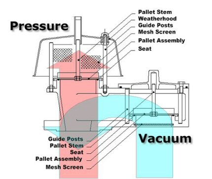 However, when you purchase new tires, the tire valve stem is not included.
The valve stem sizes you need depend on the rim size. Low-profile rims (up to 0.9″) will need a 1.5″ stem while a 1.3-1.7″ rim should have a 2.3″ valve stem. Anything taller than 1.9″ needs at least a 3.1″ valve stem to properly function.
To find a slow leak in a tire, you will needs a spray bottle and soapy water. Mix liquid soap and water in a spray bottle and spray the entire tire (sidewalls, tread area, along the rim, and the valve stem). The slow leak will be there the soapy water forms small bubbles with the escaping air.
Air pressure escapes the tire when the valves are open because of the different pressure levels inside the tire and in the atmosphere. The high pressure of the tire flows out until the tire features the atmospheric pressure. This causes the tire to go flat.
Page not found. Wrong address typed or such page does not exist
Vacancies
Delivery
 4 (Whole welded)
  ZRD pressure regulator.
 Pressure regulator ZRD.
ZRD pressure regulator
1-check valve, 2, 12 - guides, 3 - shut-off valve, 4, 10 - springs, 5 - screw rod, 6- filter, 7- locknut, 8- shaped nut, 9- body, 11-closing valve, 13- check seat valve
Pressure regulator ZRD is used on diesel locomotives with diesel driven compressor. Pressure regulator (Fig. 3.15.) consists of a body 9 , in which there are two screw rods 5 with 8 shaped nuts, 7 locknuts and adjusting springs 4 and 10 . Ledges of shaped nuts are placed in the vertical groove of the body 9 , which excludes their rotation on the screw rods 5 .
Spring 4 rests against the shut-off valve 3 and spring 10 against the closing valve 11 . The lower end surface of valves 3 and 11 is made combined - in the form working and stall (ring) areas. Valves 3 and 11 have the ability vertical movement in guides (nests) 2 and 12 . Saddle 13 screwed into guide 12 spring loaded check valve 1 . Internal cavity of the body the regulator is divided by partitions into three chambers: the shut-off valve (left), main tank (middle) and switching valve (right). In the middle chamber of the body is located filter 6 with horse hair.
Spring 4 shut-off valve adjustable to pressure 8.5 kgf/cm 2 a closing valve spring 10 - for 7.5 kgf/cm 2 .
Spring force adjustment 4 and 10 are made by turning the screw rods 5 . In this case, shaped nuts 8 , moving in the vertical direction, change spring tightening force. Idle switch pressure adjustable rotation of the left screw rod 5 , but for work move - right rod. After adjustment, the rods 5 are fixed lock nuts 7 .
To the bottom of the housing (attachment (GR) and ¼ " threaded pipes from the (RUK) compressor unloaders mounted on the suction valves. On the regulator body there is an atmospheric outlet (At) .
Compressor running under load compressed air from GR passes into the middle part of the pressure regulator, from where it enters through the filter 6 under the shut-off valve 3 , acting on its working area, and to the check valve 1 . At this moment, the camera including valve, pipeline RUK to unloading compressor devices and therefore, the cavity above the diaphragm 14 (Fig. 3.4.) communicated with the atmosphere through the hole At . When the pressure in GR is increased to 8.5 kgf/cm 2 the shut-off valve 3 will move away from its saddle up. In this case, the air pressure extends to a large (stall) valve area, which causes its clear rise.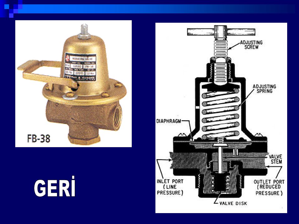 Opening the shut-off valve 3 allows air to pass under the shut-off valve 11 , which also opens (rises up) because it spring adjusted to pressure 7 , 5 kgf/cm 2 . The switching valve, resting against the top end part guide (sockets) 12 , disconnects right chamber regulator from channel RUK . At the same time, channel RUK ceases to communicate with the atmosphere, and the right camera The regulator continues to communicate with At .
Rising up, switching valve 11 provides air passage from GR into the channel RUK through the previously opened shut-off valve 3 and releases the check valve 1 , which rises with its spring up (opens) and also starts pass air from GR into the channel RUK , and at the same time along the lower horizontal channel in the mating part - into the chamber (left) of the circuit breaker valve. The increased pressure in the left chamber of the regulator, together with the spring 4 , ensures seating (closing) of the shut-off valve 3 . With this position of the valve 3 , the air in the channel RUK will only pass through the open check valve 1 .
From channel RUK air passes into the cavity above diaphragm 14 (Fig. 3.4.) compressor unloaders. At diaphragm 14 bends down and acts on piston 13 which, overcoming the force of the springs 12 and 10 , moves down the rod 11 and stop 9 . Last with his fingers, presses the valve plates of the suction valves from the seat and holds them in this (open) position. The compressor goes into idle mode, at which LPC suck air from atmosphere and push out it back through the suction filters, and HPC sucks in the air left in the refrigerator and pushes it back into the refrigerator.
After depressurizing GR to 7.5 kgf/cm 2 spring 10 lowers the closing valve 11 onto the seat, which moves down (closes) the check valve 1 .