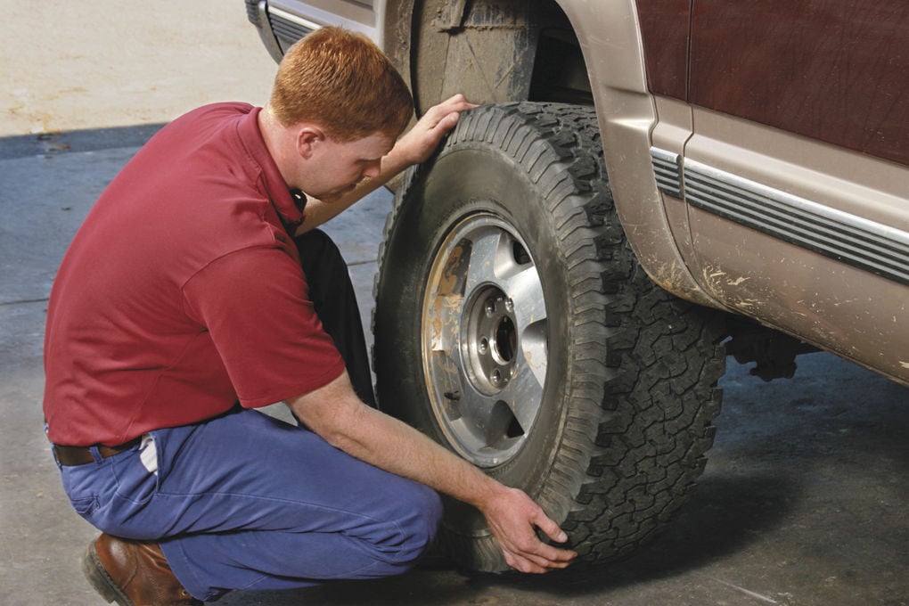
Flat tires are a common occurrence when traveling by car. You can have many options to fix this problem, but using a flex seal on tires is the fastest temporary solution.
Although this flex seal is not suitable for high pressure, it is an effective tool for flat tires. Let’s explore the following article to understand better the cause of a flat and how to use a seal on tires to fix it.
Buy Flex Seal on Amazon
What Causes Your Tires To Collapse?Flat tireFirst of all, you need to know the information about the cause of your flat one so that you can prevent it and find the best way to fix it. In fact, many factors lead to this unexpected incident, as common as:
Punctured by sharp objectsWhile traveling on the road, there can be a lot of sharp objects such as dams, metal pieces, glass shards, or nails, and more than your car can run over. At that time, you will feel your wheel deflate quickly.
Sharp object puncture is a fairly common incident for motorists. Moreover, this incident is quite unexpected, making it difficult for you to avoid. But it is better not to drive too fast because if you hit a nail at high speed, your car may overturn.
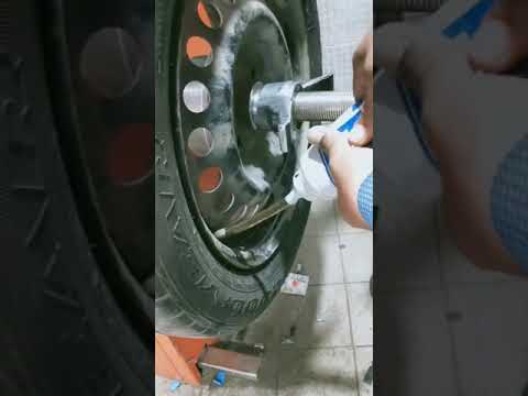
Damage to the valve bodyValve bodyThe valve body is an important part because if this part is damaged, it will cause the tires to deflate and deflate quickly. Physical impacts can damage this valve body from the outside.
Besides, if your valve body is too dirty or not tight, creating a gap is also the cause of reduced pressure. Over time, it can make your car flat and can be dangerous for you on the road. Therefore, after each time the valve tower inflates, pay attention to check and tighten it.
Tire is rubbed or tornRubbed wheelThe problem of a flat tire can also stem from the cause of your tires being worn and damaged. If you often travel on rough roads, the tires will wear more.
In particular, old tires are often easily worn and out of air quickly, and deflation occurs. Therefore, it is better to check the condition of the tires regularly to replace them in time to ensure safety when traveling.
Grain leakPressure can also decrease due to air leaking from the beads, which are the edges on the rim. Usually, this process is very slow, and you can hardly detect it.
So, to check for this problem, you need to spray soapy water on your wheels and valves and watch. If tiny balls appear, it is a leak. Also, you need to check the whole to detect the exact cause of the tire deflation.
Buy Flex Seal on Amazon
Can A Flex Seal Fix A Tire?Flex Seal Fix A TireSure, a flex seal can fix a tire, and it’s a great way to fix it quickly and efficiently.
With its easy-to-stick characteristics, properties such as tire rubber components, and sealing ability, flex seal can fix air leaks.
If you need to travel on a long journey, it is better to have a spare tire, pump, and carry some flex seal to fix the problem yourself. In particular, if your car accidentally bites a sharp object, you will find flex seals really useful.
When you find a flat tire, it’s important to check what’s causing the problem. Flex seals help seal leaks quickly and keep you moving normally.
So, to fix a flat problem in deserted areas, you can check for cracks and use a flex seal to seal and inflate to move forward.
However, we do not recommend using more than one of these products on the same tire. When there are too many flex seals on the tire, they can cause the wheel to clump, which is dangerous for you.
For more details, check out this video below:
Does Flex Seal Work On Rims?The simple answer is maybe because Flex Seal also comes in liquid form, you can also use it as a rubber coating to protect the rim.
The job of this layer is to keep moisture to limit the impact of debris, stones, and other factors impacting on the rim.
The use of Flex Seal for rims is an interesting idea to help limit physical impacts on the rim. As a result, it will be more durable, less prone to scratches, abrasion, or oxidation.
As such, this product is highly applicable, and you can use it not only for tire repair but also to protect other vehicle parts effectively.
Is Flex Seal Permanent?People are also interested in the durability of Seal. Some argue that they will last forever. This opinion may be true, but not all types have such ideal durability.
The durability of Seals will depend on many factors, including the environment, the paint layer added, and the maintenance mode. Therefore, to increase the durability of this product, periodically maintain and check them.
At the same time, the best way to have seals with high durability is to choose to buy quality products at reputable addresses.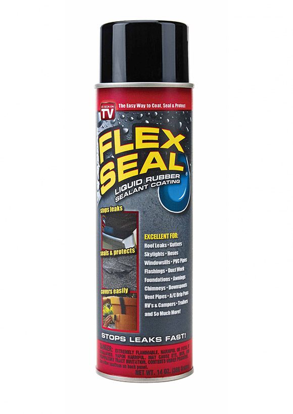
Statistically, this product can last for many years without cracking, peeling, or losing any of its strength or tightness properties. Therefore, it has quite a good durability. However, it is difficult to confirm it is permanent because it can be affected by several factors other than the environment.
Some people consider 24 months as the period in which Seals stay at their best.
Understandably, this product will last the life of your tire. And when the tire has deteriorated, you should also replace it with a new one to ensure your safety, especially on long trips.
Buy Flex Seal on Amazon
ConclusionIn short, a flat tire is an incident that can often happen unexpectedly when you are in traffic. Then, using a flex seal on tires is an optimal solution to help you fix it temporarily before going to the repair center.
Hopefully, with the information we shared in this article, you can understand the causes and how to fix the problem. We hope you have safe and smooth journeys!
by Hank Brown
Categories Cars
There are a lot of problems that can be experienced in a vehicle. Especially for the tires, there are a lot of situations that you can be under. Tires can be flat, or they might leak.
With that, as a car driver, you will look for ways to fix your tires. So we have created this article. Many people ask about flex seals, how effective they are, and how they work with their tires.
With that, we will be talking about flex seal for tires. Let us get started.
Table of Contents
A flex seal is not made to be used on high-pressure applications. If there is an extreme emergency, it can be used as a temporary repair for an inner tire tube. If you want it to be successful, you have to use multiple overlapping layers of Flex seal.
Because of the inherent risks of highway use, it is recommended that licensed mechanics repair the car’s tires. So it is not recommended to use Flex Seal to repair an automobile tire.
Flex seal will stick to any surface that is wood, porcelain, concrete, tile, metal, plastic, fabric, glass, drywall, rubber, cement, or dry surfaces. Flex seal will also work on roofs, windowsills, gutters, skylights, downspouts, awnings, chimneys, campers, trailers, and many more. It can also be applied to plastics, masonry, and more.
Flex seal will stick to any surfaces like metal, rubber, glass, aluminum, porcelain, plastic, vinyl, and many more. However, the flex seal might not be compatible with the vinyl, rubbers, or plastics.
Flex seal will work on windowsills, flashings, gutters, roofs, downspouts, awnings, vent pipes, campers, trailers, and many more. In addition, you can apply it to wood, concrete, copper, masonry, glass, plastics, and many more.
They will let the flex seal dry for two days to ensure the most accurate results. Then, they will then run water over the leak.
Many do not recommend using flex seal liquid to repair an automobile tire. Therefore, it is not recommended to use flex seal liquid for an automobile tire.
Car drivers want to know if a flex seal can work on inner tubes. It is not recommended to use a flex seal to repair an automobile tire. They can stick to almost any surface like fabric, glass, aluminum, or plastic.
In addition, a flex seal is not made to be used for applications with high pressure. However, you might be in an emergency, and it can be used to repair an inner tire tube temporarily.
People want to know if a flex seal can work on inner tubes.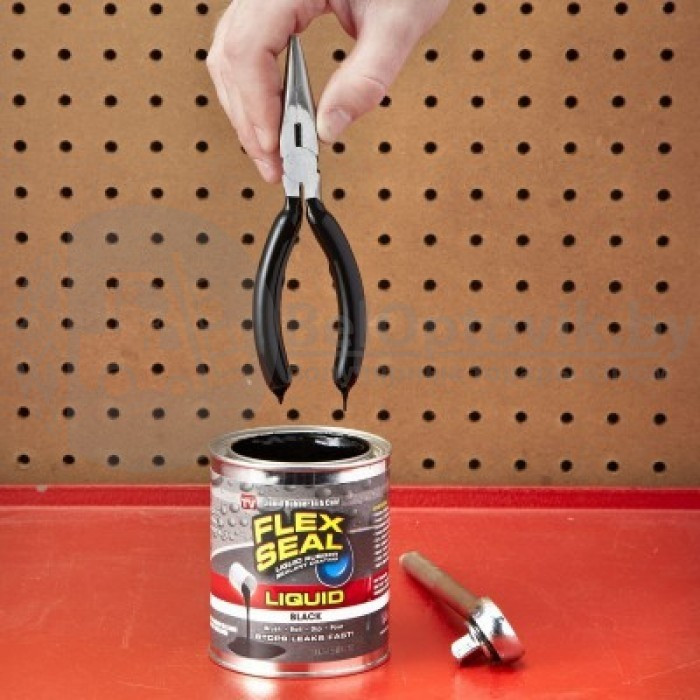 A flex seal is not made to be used for high-pressure applications. However, it can repair a bicycle tire inner tube in an emergency.
A flex seal can be fine on trailers or trucks, but not for mowers. You must go forty-five miles per hour.
A flex seal has toluene. It is a solvent that is powerful enough that you can turn shoe rubber into an erase-like paste. This makes sense that this toluene will dissolve paint and destroy tires.
Flex Seal is a flexible liquid and a rubberized liquid. It can be used to repair the puncture hole in bike tires.
In summary, people want to ask so many questions about flex seals. Flex Seal can be used for car troubles.
However, not all car troubles can be used for it. There are also limits to what Flex Seal can do.
Also Read:
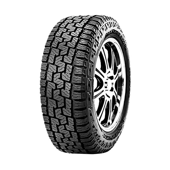
 265 Tires
Image credits – Canva
PUMPING
EQUIPMENT
SITE OF
OFFICIAL DEALER AND AUTHORIZED
SERVICE PARTNER
GRUNDFOS - CJSC SINTO
The page you requested was not found. We may have removed or moved it. Perhaps you came from an outdated link or entered the address incorrectly. Use the search or sitemap.
 ) Polydos, KD
  Basic concepts and definitions. Dosing and disinfection
 Concrete compaction equipment
Concrete mixture in the manufacture of reinforced concrete products and structures is compacted by vibration, centrifugation, vibration stamping, vibration rolling and pressing. The choice of method for compacting the concrete mixture depends on the configuration, design and purpose of the reinforced concrete product and the technology adopted for its manufacture.
In transport construction, two methods of concrete mixture compaction are mainly used: by vibrating with the help of special vibration mechanisms (vibrators) and by centrifugation, i.e. in special machines using centrifugal force.
Vibrators used to compact the concrete mixture are classified according to the type of drive and the method of transmitting the vibrations of the concrete mixture. Depending on the type of drive, they are divided into electric, pneumatic and hydraulic. Electric vibrators are divided into electromagnetic and electromechanical.
According to the method of transmitting vibrations, surface, external, deep and machine vibrators are distinguished.
The vibration source of any vibrator is a vibration mechanism, the design of which depends on the purpose of the vibrator. The most common are unbalance, electromagnetic and pneumatic vibration mechanisms.
Unbalance vibratory mechanisms are produced in two types: the mechanism of the first type is a hollow body, inside of which an unbalance is mounted on two ball bearings. The unbalance is rotated by a rigid or flexible shaft connected to the motor shaft. When the unbalance rotates, circular vibrations occur, transmitted through the bearings to the housing, and from it to the compacted concrete mixture. The vibration frequency of the body corresponds to the number of revolutions of the shaft on which the unbalance is installed. Such vibration mechanisms are used in internal vibrators.
Fig. 1. Schemes of vibration mechanisms
Fig. 2. Schematic diagram of pneumatic vibrating mechanism
The unbalanced mechanism of the second type is a hollow body, inside of which there is an electric motor with one or two unbalances. When the motor shaft rotates, unbalances create circular vibrations, which are transmitted through the bearings to the vibrator housing or the working platform (depending on the design of the vibrator). This principle of operation for deep, surface, external and easel vibrators.
The electromagnetic vibrator is a platform mounted AC electromagnet. The core of the electromagnet is rigidly fixed in the center of the working platform, and the armature is connected to the working platform of the electromagnet by means of lugs and bolts with springs. An alternating electric current, passing through the winding of a coil put on a core, creates an electromagnetic field that causes the armature and core to periodically attract and repel them under the action of a spring. The frequency of the oscillations created in this way depends on the frequency of the alternating current flowing through the winding of the core coil.
Such mechanisms are used in vibrating platforms, vibrating screens and feeders.
Pneumatic vibrating mechanism is a cylinder, inside of which there is a piston, which reciprocates under the action of compressed air. Compressed air enters the cylinder through the junction box alternately from the right and left sides of the piston through the inlet channels and bypass channels. The speed of the piston, and hence the frequency of oscillation of the vibration mechanism, depends on the pressure of the compressed air entering the cylinder.
The planetary vibrator has a ring in the housing. A slider mounted on a rod rolls along the treadmill of this ring. The rod is rotated by the motor shaft through a hinge.
Fig. 3. Diagram of the electromagnetic vibration mechanism
Fig. 4. Scheme of the planetary vibrating mechanism
The oscillation frequency in planetary vibration mechanisms depends on the number of revolutions of the rod on which the slider is fixed, as well as on the diameter of the slider and the treadmill.
Surface vibrators transmit the vibrations of the concrete mixture with their working part, installed directly on the surface of the compacted layer. These vibrators are used in the construction of road surfaces, floors, etc.
Electromechanical surface vibrator consists of a metal trough and an unbalance vibrating mechanism bolted to the trough.
The vibration mechanism is mounted in a housing and is an asynchronous electric motor with two unbalances.
External vibrators are mounted on the formwork of the concrete product or structure and transmit vibrations of the concrete mixture through this formwork. Such vibrators are used for the construction of columns, vaults, pipes and other monolithic reinforced concrete structures, as well as for the manufacture of large reinforced concrete products in molds. In addition, these vibrators are used to facilitate the unloading of materials from dump trucks and bins, passing materials through chutes and through screens.
External pendulum type vibrator has a specially designed asynchronous squirrel-cage motor stator fixed in two elongated bearing shields acting as pendulum arms. The lower ends of these shields are connected with the base working plate of the vibrator by means of bearings and axles. Sector unbalances are installed at the output ends of the motor rotor shaft. They are closed with covers bolted to end shields.
Internal vibrators transmit the vibrations of the concrete mixture with their body immersed in the mixture. These vibrators are used to compact large masses of concrete mixture in the construction of large structures from monolithic concrete.
Internal vibrator with flexible shaft and unbalanced vibrating mechanism consists of a closed-type electric motor with a gearbox, a flexible shaft and a vibrating tip, inside which an unbalanced vibrating mechanism is placed.
Electromechanical vibrators are produced with a power of 0.2 to 4 kW with an oscillation frequency of 6 thousand, 10 thousand and 20 thousand per minute and a driving force of 130 to 3000 kgf. In addition, there are pneumatic vibrators with the number of vibrations from 2 thousand to 18 thousand per minute.
Fig. 5. Surface vibrator
Fig. 6. External pendulum vibrator
Fig. 7. Flexible Shaft Vibrator
-
Concrete mixture or mortar is saturated with air during mixing, transportation, distribution and laying in a form (formwork). Various mechanical compaction methods are used to remove air from the mixture. A few seconds after the start of mechanical action on it (compression - rolling, vibration, exposure to centrifugal forces or vacuum, etc.), the mixture turns from a gelatinous state into a heavy liquid, fills all parts of the molds, envelops the reinforcement, the surface of the concrete mix occupies a horizontal position while the air bubbles go up. The duration of the mechanical action on the mixture depends on its rigidity and usually does not exceed several minutes. With an excessively long exposure, the mixture is stratified - a large aggregate sinks to the bottom of the mold, the reinforcing cage is displaced, etc.
In the repair and construction of buildings, vibration and less often vacuum methods of compacting the concrete mixture are used. Vibration compaction is based on the communication of harmonic vibrations of the concrete mixture, as a result of which, due to the impact on the components of alternating velocities and accelerations, the bonds between the components are broken. With an increase in the amplitude and frequency of vibrations, the intensity of the destruction of bonds between the components increases, while the productivity of the vibrocompactor increases.
According to the type of vibration exciters, vibration devices are divided into eccentric, in which vibrations are created due to the rotation of an unbalanced unbalanced mass, and into machines, in which vibrations are created due to the reciprocating movement of a certain mass. As a driving force in vibration devices, compressed air, electromagnetic fields or a mechanism driven by an electric, hydraulic and pneumomotor or an internal combustion engine are used.
According to the shape of vibrations, vibrators are divided into vibrators with circular and rectilinear vibrations.
By design, vibration devices are divided into surface, deep with a remote or with a built-in engine. Some types of vibrators are used to vibrate various devices and systems, and therefore they are attached to molds for the manufacture of products, to bunkers, skips, etc.
Surface vibrator is a trough-shaped shield 6 with handles for its movement on the surface of the product. A vibration element is attached to the shield, consisting of an electric motor, a rotor, at the ends of the shaft of which unbalances are installed in the form of a semicircle or sector.
The electric motor is supplied with alternating current from a safety voltage network of 36 V, 50 Hz using a plug connector. Shaft speed - 2800 min-1. The mass of the vibrator is 53 kg;
Fig. 8. Surface vibrator
Unbalance consists of two plates, by turning them on the shaft relative to each other, you can change the value of the unbalanced mass from zero to maximum. As the disturbing force increases, the sealing performance increases. However, at the same time, energy consumption increases, noise increases and the destructive effect on the metal structure of the installation increases.
Surface vibrators are widely used in the construction of floors for compaction and leveling of concrete mixtures with a layer thickness of up to 0.15 m.
A variety of surface vibrators are vibrating slats (vibrating bars), on which several vibrators are sometimes installed. With the help of vibrating screeds, it is possible to level and compact the mixture in the manufacture of concrete paths, driveways, floors, corridors, etc.
Deep vibrator (vibrator head) with built-in electric motor is shown in fig. 9. During operation, these vibrators are immersed in a mass of concrete mix. The domestic industry produces vibrators weighing 9, 15 and 22 kg with an oscillation frequency of 183 s-1, a body diameter of 50, 75 and 100 mm, a disturbing unbalance force of 2. 5; 5.5 y \ 10 kN. The vibrator consists of a cylindrical body in which an electric motor and an unbalanced shaft are mounted. The housing is connected to the control handle through a rubber coupling, which dampens the vibration transmitted to the worker's hands.
Fig. 9. Deep electromechanical vibrators:
a, b - unbalanced vibrators with built-in electric drive; c - deep electromechanical vibrator with a flexible shaft; d, b - vibrotips with unbalance-runners with internal and external running; 1 - vibration exciter; 2 - hose with cable; 3 - switch; 4 - handle; 5 - unbalance; 6 - bearings; 7 - electric motor; 8 - flexible shaft; 9 - vibrotip; 10 - spindle; 11 - elastic coupling; 12 - unbalance slider; 13 - running surface
Internal vibrators with a flexible shaft are widely used in the manufacture of monolithic structures. They have a small diameter and mass of the working body, which allows them to be immersed in hard-to-reach places between the reinforcement bars. The vibrator consists of an electric motor with a carrying handle and a switch connected by means of a flexible shaft to the tip. Inside the tip is a planetary vibration exciter. The exciter is made in the form of a composite .cylindrical body with a massive part at the bottom, machined at the end. A bearing assembly is screwed into the upper part, through which a flexible drive shaft passes. A runner in the form of a rod is attached to the end of this shaft through a rubber sleeve, at the end of which there is a conical thickening.
Fig. 10. Trowels:
a - single-deck with elastic suspension; b - two-disk with a rigid suspension; 1 - trowel discs; 2 - reducer; 3— electric motor; 4 - control knob with a fitting and a valve for water supply; 5 - output shafts of the planetary gearbox
Internal vibrators used at construction sites have a mass of 26...59 kg, a vibration exciter body diameter of 28...76 mm, an oscillation frequency of 334...175 s-1 and a disturbing force of 1. 8. ..4.0 kN.
In recent years, construction sites have begun to use vacuum methods of compaction and dehydration of concrete mixtures with a layer thickness of up to 0.15 m. m) connected by flexible pipes (diameter 0.06 m) to a vacuum pump with a power of about 5 kW and giving 80% vacuum. The lower part of the beam has many small holes. In the process of moving the beam along the surface of the concrete, air and excess water are sucked out of the concrete mixture. After vacuum treatment, the surface can be smoothed immediately. This method of compaction is highly productive and noiseless, but it requires additional time to perform a number of preparatory work.
After compacting the concrete mixture and checking that its surface conforms to the required marks, they begin to smooth the surface. Various manual machines are used for smoothing (grouting).
A trowel with a textolite disc working body is shown in fig. 10. The machine is designed for smoothing a layer of plaster or, in some cases, a sand-cement mortar when processing concrete surfaces. The disc diameter is 0.3 m, weight is about 3 kg. The machine has a pneumatic rotary four-blade motor, a two-stage planetary gearbox and a working body. Machine components are mounted in an aluminum handle housing, the configuration of which makes the machine suitable for smoothing vertical surfaces. The machine has a wetting device in the form of a tube with holes for supplying water to the smoothed surface. In order to obtain the required surface quality, it is necessary to use fine-grained sand for the solution, and start smoothing after a certain exposure of the plastered surface.
For finishing operations, a machine designed also for plastering is used. It has a working body in the form of concentrically arranged rings with a diameter of 0.22 m and a disk with rubbing surfaces made of wood, foam plastic, chipboard, felt or nylon. The drive of the working body is carried out from a high-frequency motor, on the shaft of which there is a gear, which is engaged with the internal teeth of the ring drive gear and with the disk drive gear. When the motor is turned on, the disk and ring rotate in different directions. The car has the union for water supply to the rubbed surface.
Fig. 11. Manual trowel
DZM-9B type machines (Fig. 11) are used for smoothing the surface of freshly laid concrete floors (drives, paths) or various monolithic concrete structures. This machine contains a high-frequency electric motor with a squirrel-cage rotor, a disk working body, a two-stage gearbox, a hinged lever with a switch, a carrying handle and a current-carrying cord with a plug connector. To smooth down, you need to press the stopper, lower the lever and pull the trigger. In the process of work, in order to achieve the required quality of smoothing, the machine is informed of circular and translational movements. Machine weight 8…15 kg. The circumferential speed of the disc is 8 ... .10 m / s with a diameter of 0.4 ... 0.6 m. The required cleanliness of smoothing for surfaces going for painting or wallpapering is 0. 6 ... 1.2 mm, for floor surfaces in common areas - 0.3 ... 0.6 mm, for floors covered with linoleum - 1.2. ..2.5 mm.
Block vibrating plates
Vibrating platform SMZH-200G with a load capacity of 15 tons with vertically directed vibrations for forming products with a plan size of not more than 3X6 m consists of eight identical vibrating blocks (maximum load capacity of 2 tons) with two-shaft unbalanced vibration exciters of vertically directed action and electromagnets arranged in two rows and connected between each other by cardan shafts.
Fig. 12. Concrete paver type 2.296
Fig. 13. Vibrating platform SMZH-200G
The vibrating platform is driven by four electric motors. All four shafts of electric motors rotate synchronously thanks to mechanical synchronizers. To reduce noise, a metal casing is provided.
The twin-shaft exciter is a cast steel housing containing two parallel vibrators. Shafts are supported by spherical roller bearings. On each shaft of the vibration exciter there are two unbalances, each of which is a sector fixed on the shaft with an attached replaceable unbalance.
For the bearings of the vibration exciter of the vibrating platforms, a liquid lubricant is used, which is poured into the vibration exciter housing to the level of the axis of the lower rollers of the bearings.
Vibratory block elastic suspension consists of four pairs of cylindrical springs and tie bolts, with which the vibrating block is attached to the support frame. Two beams located between the lower and upper pre-compressed suspension springs securely fix the vibrating block against lateral displacements.
The electromagnet is used to attract the form (pallet) to the surface of the vibrating block, which is the supporting surface for the form. The electromagnet is a massive steel case in which a coil of aluminum wire is embedded. The ends of the wire are brought out to the terminal box. With the help of lamas and bolts, the body of the electromagnet is attached to the body of the vibration exciter.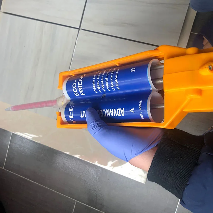 The electromagnet coil is powered by 110 V direct current from a selenium rectifier. The gaps between the coil and the body are filled with bitumen. For the normal fastening of the form to the vibrating platform during the compaction of the concrete mixture, it is required that the holding force of the electromagnets exceed the force of separation of the form, which arises from the dynamic forces acting on it.
The vibration platform SMZh-187G has a similar design, differing in the number of vibration blocks, the distance between them and the drive power. In addition, the vibration platform SMZH-187G, in contrast to the vibration platform SMZH-200G, has a one-way drive.
Along with block vibration platforms with vertically directed harmonic vibrations, vibration platforms SMZh-538A, SMZh-773 and SMZh-774 with shock vibrations are produced.
Vibrating platform SMZh-538A has four separate vibrating blocks attached to a common frame through rubber elements, located across the longitudinal axis of the mold. The distance between the axes of the vibroblocks is assumed to be the same as for the vibrating platforms SMZh-187G and SMD-200G—1700 mm.
On top of each vibrating block, there are two pads made of thick rubber, on which the form rests. In the SMZh-538 modification, IV-96 vibrators are used as a vibration drive, two for each vibrating block; in the SMZh-538A modification, the vibrators are replaced by two rows of unbalanced shafts connected to each other by cardan shafts; each row of shafts is driven by its own electric motor.
Vibrating platform SMZh-773 is arranged according to the scheme of block vibrating platform SMZh-187G, has a one-sided drive from two electric motors, mutual synchronization of rotation of two rows of vibrating shafts, electromagnetic fastening of molds and is distinguished by half the frequency of rotation of the drive electric motor and the design of the suspension of vibrating blocks, providing shock vibration mode.
Vibrating platform SMZh-774 consists of two vibrating platforms installed along a common axis with four vibrating blocks in the form of transverse tables with two vibrating shafts. Each vibrating shaft has its own drive. Vibroblocks are based on stationary frames through an elastic suspension system. Electric motors of drives are located on opposite edges of the vibrating platform. There are no mechanical synchronization, as well as mold fixing. The form is established on basic elements with rubber laying. The elastic suspension system of the blocks provides shock operation. Oscillation frequency 25 Hz.
Frame vibratory plates
The most common frame vibration platforms are vibration platforms with multi-component low-frequency vibrations excited by one or two adjustable vibration exciters with a vertical shaft, designed by ECB "Vibrotekhnika" of the Poltava Civil Engineering Institute. The movable frame rests on elastic rubber-metal bearings fixed on the frame installed on the foundation. An unbalanced vibration exciter with a vertical shaft is attached to the movable frame, driven by an asynchronous electric motor through a V-belt transmission. The engine is mounted on a sub-frame mounted on the foundation.
The fundamental feature of the vibrating platform is that the plane of action of the unbalance driving force does not coincide with the center of mass of the moving parts of the Vibratory System of the vibrator. The height displacement of the vibration exciter relative to the center of mass provides, in the presence of elastic supports, the rigidity of which is different horizontally and vertically, the multicomponent nature of the vibrations of the movable frame with elliptical trajectories.
Horizontal and vertical components of the vibration displacement amplitudes of the moving frame points are interconnected, their required value is achieved by adjusting the static moment of the vibration exciter, and the ratio between them is achieved by installing the vibration exciter at a certain distance from the center of mass of the vibrating platform in height.
To ensure normal compaction of the concrete mix, vibration modes are used with an oscillation frequency of 20 . .. 25 Hz and vibration displacement amplitudes of 0.6 ... 1.0 mm horizontally and 0.35 ... 0.45 mm vertically.
Currently, various layouts of vibrating platforms have been developed, designed for the formation of certain types of reinforced concrete structures that differ in weight and size.
Two types of unified vibration exciters VU-10rs and VU-25rs are used in vibration platforms.
Depending on the purpose, the vibration platforms are assembled with one or two vibration exciters installed at the ends, on the side or in the middle part of the frame.
For ease of calculation, a shockless vibratory platform with vertically directed vibrations is reduced to a linear system with one degree of freedom. The required vibration frequency and vibration displacement amplitude are specified by technological requirements. The total amplitude of the driving force developed by all in-phase rotating unbalances,
Fig. 14. Frame vibration platform
Fig. 15. Vibration exciter
1 - drive pulley; 2 - body; 3 - housing cover; 4 - unbalance shaft; 5 - removable load; 6 - unbalance; 7 - window cover for installing interchangeable weights
Forming machines and plants
Machine SMZh-227B for molding floor panels consists of a carriage, a drive for hollow formers, right and left chain supports, a support with sprockets, electrical equipment and pallet stops.
The carriage is used for inserting the core formers into the mold and removing them from it after molding the products. It is a portal-type structure supported by four wheels and moving along rails.
The carriage drive consists of a motor, a brake, a gearbox, a drive sprocket, a gear coupling, a drive shaft with an asterisk and two drive chains, the ends of which are fixed to the carriage using special rods and pins. The drive is mounted on a frame mounted on a foundation.
Fig. 16. Molding machine SMZh-227B
To support the chains on the foundation, channel supports are installed, on which limit switches are placed that limit the movement of the carriage.
The changeover of the machine for the production of a product of a new standard size consists in installing the core formers of the appropriate size and rearranging the limit switch to the required distance, which limits the carriage travel when the core formers are inserted into the mold.
In the machine SMZh-227B, vibration-free void formers are used, designed for the use of vibration platforms.
In the SMZh-227 machine of previous modifications, vibro-hollow formers were used, which provide deep compaction of rigid concrete mixtures and immediate stripping without the use of vibration platforms at the molding stations.
The vibro-hollow former is a steel pipe with a diameter of 159 mm and a wall thickness of 6 mm, inside which three vibrogroups are freely placed with a gap of 0.5 ... 1.5 mm, consisting of two supports with unbalanced shafts mounted in bearings. The vibration groups are interconnected by shafts with centering elements and elastic couplings.
The end connecting shaft is connected by means of a coupling to the drive shaft of the fixed carriage support, on which the electric drives are mounted in this case. Under the action of the centrifugal force arising from the rotation of the unbalanced shafts, the supports of the vibrogroups are pressed against the inner wall of the body of the void former, run in and transmit vibrations to the body.
Cassette molding machine consists of a cassette and a machine for stripping and assembling the cassettes. The unit is designed for the manufacture of panels of internal walls and ceilings used in large-panel housing construction. The machine for stripping and assembling cassettes consists of a frame, a hydraulic cylinder, a system of locking levers with shock absorbers, adjusting screws, hydraulic equipment and electrical equipment. The frame is formed by two (front and rear) racks interconnected by support beams, on which the walls of the cassette form are installed with their rollers.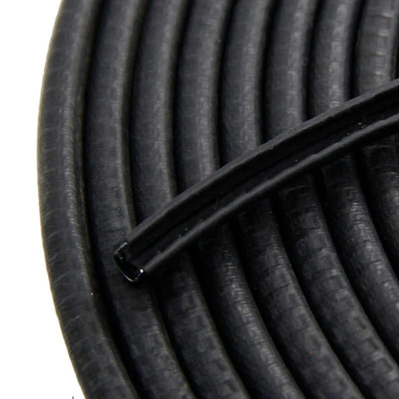 Brackets of the hydraulic lever system, hydraulic cylinder and limit switches are attached to the front rack of the frame.
The lever system is connected to the locking levers by means of rods. There are adjusting screws on the back leg of the frame to obtain the required thickness and the correct position of the package during assembly. Shock absorbers, pivotally connected to the lever system and adjusting screws, are welded to the outer surfaces of the stationary and removable walls of the cassette form. The hydraulic cylinder and the system of levers move the walls by 850 mm. The control panel and the electrical cabinet are mounted next to the cassette molding machine at the service site.
Fig. 17. Forming plant
The cassette mold is a package of metal walls and thermal compartments, between which molding compartments are formed by onboard equipment. By design features and purpose, the walls can be divided into thermal, intermediate and extreme (stationary and removable)..jpg) In the assembled form, thermal walls and intermediate walls alternate. The thermal wall, to which steam is supplied to heat the concrete mixture during heat treatment, is made of two metal sheets 24 mm thick and channels attached along the wall contour. The thermal wall must be airtight. The extreme thermal wall from the outside is equipped with a heat-insulating shield. The intermediate walls of the cassette form are made of a sheet 24 mm thick.
In the assembled form, thermal walls and intermediate walls alternate. The thermal wall, to which steam is supplied to heat the concrete mixture during heat treatment, is made of two metal sheets 24 mm thick and channels attached along the wall contour. The thermal wall must be airtight. The extreme thermal wall from the outside is equipped with a heat-insulating shield. The intermediate walls of the cassette form are made of a sheet 24 mm thick.
All walls of the mold, except for the outer one - removable, are equipped with onboard equipment in accordance with the thickness of the molded products. On the cantilever sections of the intermediate walls on both sides, IV-104 electromechanical vibrators are mounted on brackets, designed to vibrate the walls in the process of filling the cassette form with a concrete mix. The vibrators are installed so that their axis is parallel to the plane of the walls. The vibrations of the intermediate wall should be considered as forced vibrations of an elastic bar placed on two pivotally fixed supports and having two consoles to which a driving force is applied.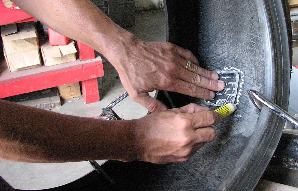 The oscillation frequency of the wall 1400 kol./min corresponds to the oscillation frequency of the vibrator. The most effective vibration is observed when the vibrator is installed on a console 65 ... 68 cm long. The vibration amplitude of the intermediate walls is 0.08 ... 0.30 mm.
At the top of the cassette form is equipped with four protective visors to prevent spillage of the concrete mixture. The steam is supplied through the sleeves to the thermal walls-compartments from the distribution combs. Perforated tubes are installed in the thermal compartments, through which steam enters the compartment. A branch pipe with a tap is provided in the lower part of the thermal compartment to drain condensate. Locks 8 are installed on the walls for their coupling. The lock bar in the upper part is connected to an eccentric, when it is turned, it rises or falls and at the same time connects or separates the mold compartments.
Brackets are welded to the upper end of each cassette wall on the right and left for fastening roller supports 9, designed to move the cassette walls along the machine frame guides during disassembly and assembly of the cassette.
Products are manufactured as follows. The compartment formed by the end stationary wall and the separating sheet is prepared for molding. After cleaning the surfaces and removing concrete residues, embedded parts and openings are installed and fixed, and the surfaces of the sheets are lubricated.
The reinforcement cage is fed into the compartment and fixed in the required position. The hydraulic cylinder moves the entire package of walls towards the stationary wall until it stops. With the help of locks, a dividing wall is attached to the stationary wall, releasing it from the rest of the package, which is retracted by the same hydraulic cylinder, revealing the next compartment for cleaning, lubricating and reinforcing cage seams. Then the package is brought in by a hydraulic cylinder, the next wall is left, closing the second compartment prepared for concreting, and the package is pushed back, revealing the third compartment, and so on until the last compartment. The last one is the removable wall. Locking levers compress the entire package.
The stripping machine is designed with two automatic bag locking mechanisms that protect the cassette from spontaneous opening during molding and heat treatment of products.
The first mechanism that performs the primary locking of the cassette package works as follows. Due to the displacement (eccentricity) of the folding levers from the central hinge downwards relative to the axes of their extreme hinges, the horizontal force from the expansion of the cassette package keeps the levers from spontaneous folding (when the drive of the pumping station is turned off due to the presence of the above eccentricity between the axes of the locking levers).
The second mechanism performs the secondary locking of the cassette pack.
Form prepared for concreting. After pouring, the concrete mixture is compacted. Next, steam is supplied to the thermal compartments of the mold and, in accordance with the accepted regime, heat treatment is performed. The form is disassembled in the same way as assembly, but in reverse order. Products eynn-mayut from the compartments with a crane.
SMZh-339A, SMZh-340A, SMZh-341A and SMZh-342, SMZh-800, SMZh-801, SMZh-802 and SMZh-803 plants are designed for the manufacture of volumetric reinforced concrete blocks of sanitary and technical cabins of the "cap" type and consist of a vibrating table, a pressing frame, liners, external side equipment, hydraulic equipment, electrical equipment and service platforms.
The vibrating table is the core of the molding machine and contains a vibrating frame, a support frame and a hydraulic drive. There are two hydraulic cylinders on the support frame, the rods of which are pivotally connected to two-arm levers connected by a common drive shaft and providing synchronous, distortion-free lifting and lowering of the extrusion frame.
The internal cavities of the cabins are formed by liners, which are an all-welded structure, the frame of which is sheathed with steel sheets. To form the outer contour of the product, four sides are pivotally mounted on the extrusion (lifting) frame. When lifting the frame, the sides with the help of rods 6 diverge. A similar device has an installation for the manufacture of tubing elevators.
Fig. 18. Installation for molding sanitary-technical cabins
The side walls of the product are filled with concrete mixture and compacted with the vibrator drive of the vibrating table turned on. At the end of the molding of the side walls, the ceiling of the sanitary cabins is molded.
After laying and vibrocompacting the concrete mix, the installation produces heat treatment of molded products, while steam is supplied directly to the internal cavity of the thermal compartments.
In the SMZh-800 ... 804 units, a fan-shaped scheme for opening the sides and pressing the cores and blanking agents down is used.
Forming machine (mould) for the manufacture of pressure reinforced concrete pipes by vibrohydropressure consists of an outer casing and an inner core with a rubber cover. The outer casing is a composite cylinder with a longitudinal split, assembled from two or four bent steel sheets. Stiffening ribs are welded to the casing. The parts of the casing are fastened with bolts with springs using flanges. Form joints are sealed with adhesive tape. The inner core consists of two steel cylinders: solid and perforated, as well as a rubber boot put on the perforated cylinder. An annular gap of 6 mm is provided between the outer and inner cylinders of the core, which is filled with water when the concrete mixture is pressed. A rubber bell-former and a steel sealing ring are put on the outer cylinder of the core.
Fig. 19. Installation for forming pressure reinforced concrete pipes with a diameter of 500 ... 1600 mm by vibrohydraulic pressing:
a - complete mold; b - cross section of the form with concrete; 1 - position before crimping; 11 - position after crimping
A stop ring is installed in the socket of the mold, and a stop ring is installed on the sleeve end, and rods of longitudinal reinforcement are passed through their holes, tying them with wire to the spiral frame. The socket ring is attached to the mold with clamps. The longitudinal rods are tensioned using a hydraulic jack, while they center the spiral frame relative to the mold walls, providing the necessary protective layer of concrete. After tensioning the longitudinal reinforcement, the gaps between its rods and the walls of the holes in the thrust rings are covered with molding clay. On the core prepared in a vertical position, the outer casing of the mold is installed with a crane. The assembled form is transferred to the concreting station, where a centering ring is installed in its sleeve end, and a loading cone with a vibrator is also fixed with rubber bands. Several pneumatic vibrators are attached to the mold platforms, depending on the size of the concreted pipe.
A vibratory plate can be used to compact the concrete mixture. In this case, the vibrators are not hung.
The concrete mixture is fed into the mold through the feed cone. During the supply of the mixture, pneumatic vibrators (or a vibrating platform) are switched on and the mixture is compacted. After filling the mold with concrete mixture, the loading cone and the centering ring are removed, and a sealing ring with a cross is installed in their place. The form filled with concrete is transferred by an overhead crane to the pressure test station.
At the crimping station, the mold is fixed in a vertical position and connected through a pipe to the water supply. The set of equipment for hydraulic sealing includes a high-pressure unit, consisting of two cylinders with a volume of 410 liters each, two pumps - high and low pressure, a compressor, a low-pressure tank and four electrocontact pressure gauges.
The essence of the process is as follows. Water is supplied under pressure into the cavity between the solid and perforated cylinders of the mold core. Penetrating through the holes in the cylinder under the rubber cover, water expands it, making pressure testing. In this case, as a result of the compression of the spring of the bolts, the outer casing of the mold opens.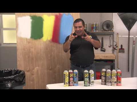 The resulting gap reaches 12 ... 15 mm. The expansion of the mold begins at a pressure of 0.25 ... 0.3 MPa. The freshly laid concrete mixture follows the deformations of the form, pulls the coils of the reinforcing cage along with it and induces tensile stresses in them, thereby straining the reinforcement.
The pressure generated under the rubber boot depends on the purpose of the pipes and their diameter. For pipes designed to operate at a liquid pressure of 1.0 ... 1.2 MPa, this pressure reaches 2.9 ... 3.4 MPa.
The subsequent heat treatment of pipes, which is carried out by launching live steam into the cavity of the inner part of the mold through the distribution ring in the lower part of the mold and under the steaming cover while maintaining the specified pressing pressure, fixes the position of the reinforcement in the stretched state until the concrete acquires high strength (30 .0… 35.0 MPa). Steaming. The cover consists of a canvas cover and a frame with a loop for connection to an overhead crane hook.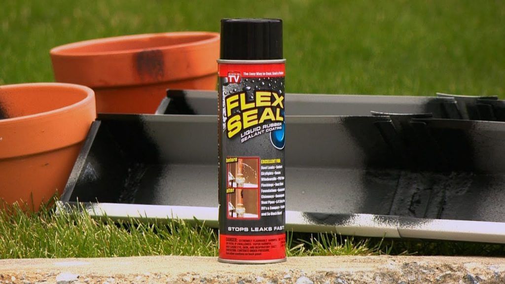 After the end of the heat treatment, the steaming jacket rises, the pressure decreases to zero, and water is removed from the inside of the mold.
The form, detached from the base, is transferred by crane to the picking pit, where the ring with the cross is removed. A vacuum system is connected to the inside of the mold, which removes residual water from the inner container of the mold.
Forming machines SMZh-194B and SMZh-329 for the manufacture of concrete non-pressure pipes with a diameter of 300 ... 600 mm and 800 ... 1200 mm by radial pressing are used in technological semi-copier lines.
Machine tools SMZH-194B, SMZH-329 consist of a traverse with a rotation mechanism, a funnel, a bell-forming mechanism, a bed with service platforms, a rotary table with a rotation drive, hydraulic cylinders, a hydraulic drive with a feeder pumping station, a feeder drive, a table clamp, a hopper, mechanism for lifting and fixing the funnel, molds and electrical equipment.
Two vertical guides are fixed on the frame, along which the traverse with the roller head rotation mechanism is raised and lowered with the help of plunger hydraulic cylinders. The traverse is a welded body; a flanged motor is installed on it, the torque from which is transmitted through the gearbox to the drive shaft. To measure the shaft speed, the gearbox has four pairs of interchangeable gears.
The drive shaft rotates in a housing mounted on a yoke. A roller head is attached to the lower end of the shaft.
The socket forming mechanism is installed under the turntable on the support frame on the same vertical axis as the traverse drive shaft and moves vertically with the help of a hydraulic cylinder along two guides fixed on the frame. An engine is installed on the mechanism case, the torque from which is transmitted through a helical gear and worm gear to the drive vertical shaft.
The form, located on the turntable diametrically opposite to the vertical axis of the machine, is rotated on the table by 180° and is placed on the vertical axis of the machine. The operator turns on the hydraulic cylinder, and the traverse, which is in the upper position, moves down. Together with the traverse, the feed funnel is lowered until the skirt of the roller head is flush with the top surface of the pallet. Then the operator turns on the rotation drive of the bell molding mechanism with its simultaneous lifting, and the vibrators start working. Rotation and vibration are transmitted to the pallet. The roller head rotation drive is turned on, the concrete mixture is fed from the feeder into the mold. After the end of the molding of the socket, the rotating roller head rises, compacting the supplied concrete mixture. After the head exits the mold, the feed funnel rises and the mold is released. By turning the carousel, the form with the product is fed to the post of its removal from the machine.
Machine SMZh-542 is designed for the manufacture of reinforced concrete rings for manholes of water and sewer networks with a diameter of 700, 1000 and 1500 mm. It consists of a rotation mechanism, a funnel, a hopper, a feeder, a carousel, a frame, a hydraulic cylinder, a pumping station, electrical equipment and equipment sets.
Fig. 20. Machine for the production of non-pressure pipes
The rotation mechanism consists of a three-speed four-stage gearbox, a main shaft and a roller head with three speeds.
Fig. 21. Centrifuge for forming racks of lighting poles and contact networks
The speed of the roller head is adjustable depending on the forming conditions and the diameter of the product.
The funnel provides the formation of the upper end of the product and the reception of excess concrete after molding. When the head leaves the mold, its rotation and lifting stops. The funnel rises, and the form with the product is fed by turning the carousel to the post of removal of the form.
Centrifuge SMZh-169B is designed for forming stands of lighting poles and contact networks up to 15.5 m long and consists of a support frame, drive rollers, support rollers, electric drive and fence.
The base frame is used to install the casters. Rollers with axles rotate in bearings installed in split housings, which allows them to be repaired without violating the regulation of the roller bearings. The base of the support rollers can be changed, which allows you to work with forms that have a bandage diameter of 490 ... 800 mm. The drive rollers of all supports are interconnected by gear couplings and shafts. The design of gear couplings allows misalignment of the shafts, which should be minimal in order to maintain shape, reduce noise and ensure the normal operation of the gearing.
To ensure the safety of the centrifuge and to prevent the mold from swinging vertically, all supports are equipped with safety levers with rollers.
The shafts of the two outer spans of the centrifuge are connected through gear couplings to the drive shaft carrying the pulley. The centrifuge is driven by two motors through a two-stage belt drive.
Work on the centrifuge begins with setting the mould. Then the lever turns the rollers of the safety device and fixes it. The operator on the control panel turns on the drive motors.
At the same time, a software timer is switched on, which controls the time required for the manufacture of the product. The transition of the centrifuge from the rotational speed at which the concrete mixture is distributed to the rotational speed at which the mixture is compacted is carried out using speed controllers.
When the mold stops rotating, the safety rollers move away from it, the fence moves away, and the mold with the product is transferred to the heat treatment by an overhead crane.
—
When compacting a concrete mixture, it is necessary to create conditions under which the particles of the mixture can take the most stable position relative to each other, excluding their further movement even in an unhardened state.
The strength of concrete is determined by the strength of the aggregates (crushed stone, gravel, sand), as well as the binder (cement), which should be as close as possible to the strength of the aggregates. At present, the strength of binders is still significantly lower than the strength of fillers used for the manufacture of reinforced concrete products, especially high grades.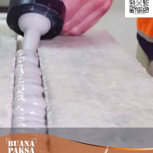
The most durable will be such concrete, in which large and small aggregate particles occupy almost the entire volume of the product, leaving the cement paste binding them into a single whole (and after hardening, respectively, cement stone) only thin layers and the smallest spaces between densely packed aggregate particles. To obtain such concrete, it is necessary to correctly select the composition of the concrete mixture and compact it with high quality.
—
Electromechanical manual internal vibrators are manufactured with a remote electric motor with a flexible shaft connecting the electric motor with a working vibrating tip, or with an electric motor built directly into the vibrator body.
During operation, the vibrating tip of a deep manual vibrator is lowered into the layer of concrete mixture to a depth not exceeding the length of the working part, and as the mixture is compacted, it is rearranged in increments not exceeding 1.5 of the vibrator's radius of action.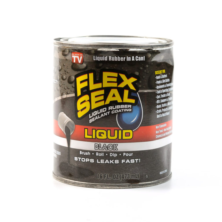
Flexible shaft manual vibrators
Internal vibrators with a flexible shaft are designed to compact concrete mixtures with a cone draft of 3-5 cm when laying them in thin-walled monolithic structures, as well as densely reinforced arrays. The distance between the reinforcement bars must be at least 1.5 of the diameter of the vibration tip.
The vibrators are equipped with an electric motor, a flexible shaft and two replaceable vibrating tips of the same standard size (the IV-47 vibrator is equipped with two flexible shafts).
In the upper part of the electric motor there is a package switch PV2-25. The electric motor is mounted on a base that ensures its stable position on a horizontal surface.
Torque from the electric motor shaft is transmitted to the vibro tip spindle through the flexible shaft using a cam clutch that allows only right rotation, corresponding to the winding of the flexible shaft.
Internal vibrators with a flexible shaft have a planetary type vibrating mechanism.
Vibrators IV-17, IV-27, IV-67, IV-66 and IV-75 have runners with external running, and the IV-47 vibrator has a runner with internal running.
The rest of the design of the vibrating tips of the vibrators is similar. Each of them is a hermetically sealed body, inside of which there is an unbalance connected to the vibration tip spindle by an elastic rubber-metal coupling.
When running unbalances on the bushing or on the core, vibration vibrations of the tips occur.
All external connections of the vibrator housings, as well as connections of the flexible shaft with the electric motor and the vibrator tip, have a left-hand thread.
The output power of the transformer must be at least 1 kVA for the IV-17 and IV-27 vibrators, and at least 1.5 kVA for the IV-47 vibrator.
The voltage at the motor terminals when the vibration tip is operating in concrete must not be lower than 34V. When the voltage drops below 34V, increase the cable cross-section or shorten its length; if after that the voltage does not increase, it is necessary to increase the power of the transformer.
Manual internal vibrators with built-in electric motor with a distance between reinforcement bars of at least 1.5 of the outer diameter of the vibrator body.
Internal vibrators with a built-in electric motor are designed for compaction of concrete mixtures with a cone draft of 1-5 cm when laying them in monolithic concrete and reinforced concrete structures.
Fig. 22. Deep vibrator IV-59
1 - body; 2 - bearings; 3 - unbalance; 4 - unbalance shaft; 5 - inclined channel of the unbalanced shaft for lifting liquid lubricant; 6 - radial hole; 7 - stator; 8 - rotor; 9- lower handle 10 - shock absorber; 11 - rod; 12 - package switch; 13 - upper handle; 14 - liquid lubricant
Manual internal vibrators with built-in electric motor IV-55, IV-56, IV-59 and IV-60 are similar in design. Their working parts are a hermetically sealed cylindrical body, inside which are built-in electric motors and an unbalance vibration exciter.
The vibrators are equipped with a three-phase asynchronous electric motor with a squirrel-cage rotor.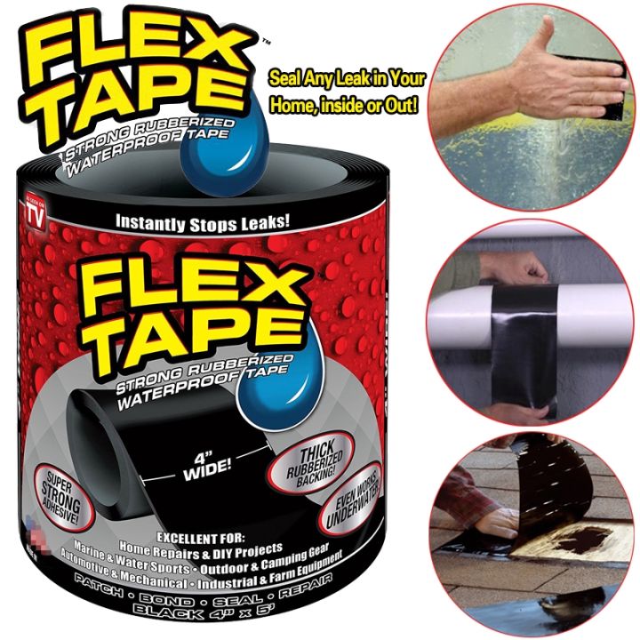
During operation, the IV-55 and IV-56 vibrators are held by a rubber-fabric sleeve that absorbs vibrations, one end of which is attached to the body of the vibrotip, and the other to a sealed box in which the PVZ-25 packet switch is mounted.
For the convenience of working with IV-59 and IV-60 vibrators, a branch pipe is welded to the upper part of their body, which is the lower part of the rod, to which the upper part of the rod with a handle and a sealed box is attached using a shock absorber. A package switch PVZ-25 is mounted in the rod box. The shock absorber serves to dampen vibrations on the upper handle.
To power the electric motors of the IV-55 and IV-56 vibrators, frequency converters S-572A, I-75V, as well as the static frequency converter CHS-4-200-36, are recommended, respectively.
To power the electric motors of the IV-59 and IV-60 vibrators, it is recommended to use frequency converters I-75V and ChS-7 with a step-down transformer TSPC-20A, as well as static frequency converters CHS-4-200-36 and CHS-10-200- 36 with a power of 4 and YukVA, respectively, with a frequency of 200 Hz and a voltage of 36V.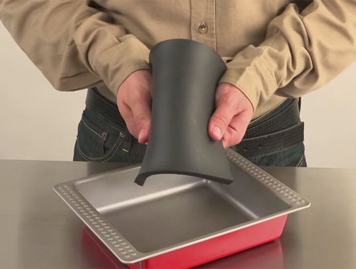 -
-
The cross section of the current-carrying core of the supply cable of the IV-55, IV-56, IV-59 and IV-60 vibrators must be 1.5, respectively; 2.5; 4 and 6 mm2.
If the voltage at the vibrator switch terminals drops below 32 V, it is necessary to stop the vibrator and provide a voltage of 36 V by reducing the cable length, increasing the cross section of the power cable or increasing the power of the frequency converter.
The length of the supply cable must not exceed 5-10 m.
When working with several vibrators from one frequency converter, the vibrators should be switched on one at a time with a delay that ensures the full start of the vibrator motor.
Only remove the vibrator from the concrete when the motor is running. During operation, the vibrator housing should be completely immersed in the concrete mixture.
Operation of the vibrator in air and with the working part not completely immersed in the concrete mixture will result in
to the rapid destruction of the insulation of the windings, since the electric motor is designed to work with intensive cooling of its concrete mixture.
During operation, it is not allowed to turn off the vibrator immersed in the concrete mixture, clamp it between reinforcing bars, press it against the formwork.
Manual pneumatic internal vibrators
Pneumatic vibrators S-697, S-698, S-699, S-700 and S-923 are similar in design and represent a hermetically sealed cylindrical body, inside which is a planetary pneumatic motor-vibration exciter.
Fig. 23. Deep pneumatic vibrator С-699
1 — case; 2 - nut; 3 - outer hose; inner hose; 5 - slider; 6 - hollow axis; 7 - scapula; 8 - end shields with exhaust holes, 9- tap; 10 - union nut; 11 - nipple; 12 - working chamber; 13 - exhaust chamber
The stator of the air motor in the form of a hollow axis with one blade stands motionless, and the rotor planetarily rolls around the stator, acting as an unbalance runner.
The blade divides the cavity enclosed between the runner and the axle into two chambers: working and exhaust. The slider is driven by compressed air entering the working chamber of the air motor through an internal flexible hose through a central hole drilled in the axle. Clinging under the action of centrifugal force to the axis, the slider rolls around it with a frequency depending on the air pressure in the network. The exhaust air enters the exhaust chamber and from there through the side holes in the shields through the outer rubber-fabric hose - to the exhaust.
The center of gravity of the slider is shifted relative to the axis of the inner hole, due to which the vibrator creates two-frequency oscillations.
The S-700 vibrator has handles for perceiving the reactive moment and making it more comfortable to use.
The C-923 vibrator is equipped with a rigid rod with two handles: upper and lower, instead of an external rubber-fabric hose. The bar consists of two parts interconnected by a rubber shock absorber.
Vibrators are started and switched off by a crane or a special starting device.
For normal operation of internal pneumatic vibrators, a hose with an inner diameter of at least 16 mm and a length of no more than 8-10 m should be used. When increasing the length of the hose, it is necessary to increase its cross section accordingly.
The pressure in the compressed air network must be at least 0.4 MPa.
Do not strain or sharply bend the hose during operation.
When working in winter conditions at negative temperatures, it is necessary to ensure that the compressed air is thoroughly cleaned from moisture in order to avoid freezing of condensate and the formation of ice plugs.
Rules for working with electromechanical vibrators when compacting a concrete mix equally apply to pneumatic vibrators.
Suspended internal vibrators
Suspended internal vibrators are used both in single execution and in the form of vibrating packages consisting of several vibrators.
IV-34 (S-827) and S-649 vibrators have a planetary-type vibration exciter with internal running of the runner. The electric motor of the S-827 vibrator is remote, and the S-649 vibrator- built into the body. The vibrators are equipped with three-phase asynchronous motors with a squirrel-cage rotor.
Vibrators united by a common frame; fastening of each vibrator to the frame is carried out by clamps through rubber shock-absorbing pads.
Sliding frame allows you to change the distance between the vibrators.
Fig. 24. Suspended deep vibrator IV-34 (S-827)
1 — core; 2 - slider; 3 - vibrator housing; 4 - rubber-metal articulated coupling; 5 - spindle; 6 - shock absorber; 7 - electric motor
Fig. 25. Package of four vibrators С-649
1 — frame; 2 - collar; 3 - terminal box; 4 - chain suspension; 5 - vibrators
The electric motors of the vibrators are powered from the mains through a busbar box mounted on the frame.
The vibration package is suspended from a crane hook or other lifting device using a chain suspension.
—
Vibrators are used to compact the concrete mixture with a frequency of oscillation (usually 3000, but sometimes 15,000 per minute) and with an amplitude of oscillation from 0. 1 to 3 mm. There are surface vibrators, deep (internal), external and easel vibrators.
Vibrators are based on vibration elements (vibration exciters): electromechanical, electromagnetic and pneumatic.
Electromechanical vibrating elements can be single-shaft, twin-shaft, pendulum and planetary. In a single-shaft element, counterweights (unbalances) are fixed on the motor shaft, the rotation of which leads to vibration. The operating voltage of the element is 36 V.
Electromagnetic vibrating element consists of base with core and electromagnetic coil, armature and springs. A selenium rectifier is included in the power circuit of the electromagnetic coil, which turns the alternating current into a direct pulsating one. Under the action of electromagnetic forces, the armature is attracted to the core 50 times per second. The accelerated withdrawal of the anchor is provided by springs.
Pneumatic vibration elements are divided into piston and planetary. In the piston element, vibrations occur as a result of the reciprocating movement of the piston inside the housing. Compressed air enters the left side of the cylinder through the pipeline, inlet channel, bypass channel and displaces the piston to the right. The air from the right cavity of the cylinder exits through the exhaust channel. Having passed the middle position, the piston closes the channels and opens the channels. At the same time, compressed air begins to flow into the right cavity of the cylinder and displaces the piston to the left. By adjusting the pressure in the supply line, the oscillation frequency of the piston changes.
Fig. 26. Vibrating elements
a - electromechanical; b - electromagnetic; c - pneumatic piston; g - pneumatic planetary
Pneumatic planetary vibratory element consists of a housing, in the end walls of which a fixed axle with a textolite blade and a rotating unbalance rotor are fixed. The blade separates the chamber into the working and exhaust cavities. Compressed air enters through the longitudinal and radial drillings in the axis into the working cavity, then into the exhaust and through the holes in the side walls goes to the exhaust.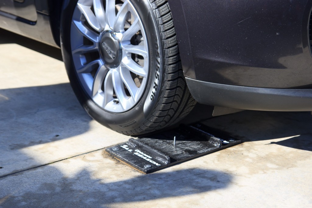
Surface vibrators are mounted directly on the concrete mix to be compacted and moved manually during operation. Such a vibrator consists of a vibrating element (electromechanical or electromagnetic) mounted on a steel trough-shaped plate, a wooden platform or an I-beam (vibrating rail). The vibration frequency of the vibrator is 2800-2850 per minute.
Fig. 27. Surface vibrators
a - vibrating platform; b - vpbrolake
Internal vibrators (immersed in concrete) include a flexible shaft vibrator and a vibrator with a built-in motor—vibrator head. To compact the concrete mixture in large, weakly reinforced massifs, package deep vibrators are used, made up of 8-16 vibrators.
Vibrator head shown in fig. 28, a, consists of a steel closed case, inside of which a shaft is placed in bearings. A counterweight (unbalance) is installed on the middle part of the shaft, and the rotor of the electric motor is installed on the console. The stator is fixed in the vibrator housing, which is attached to the rod with a handle and a switch.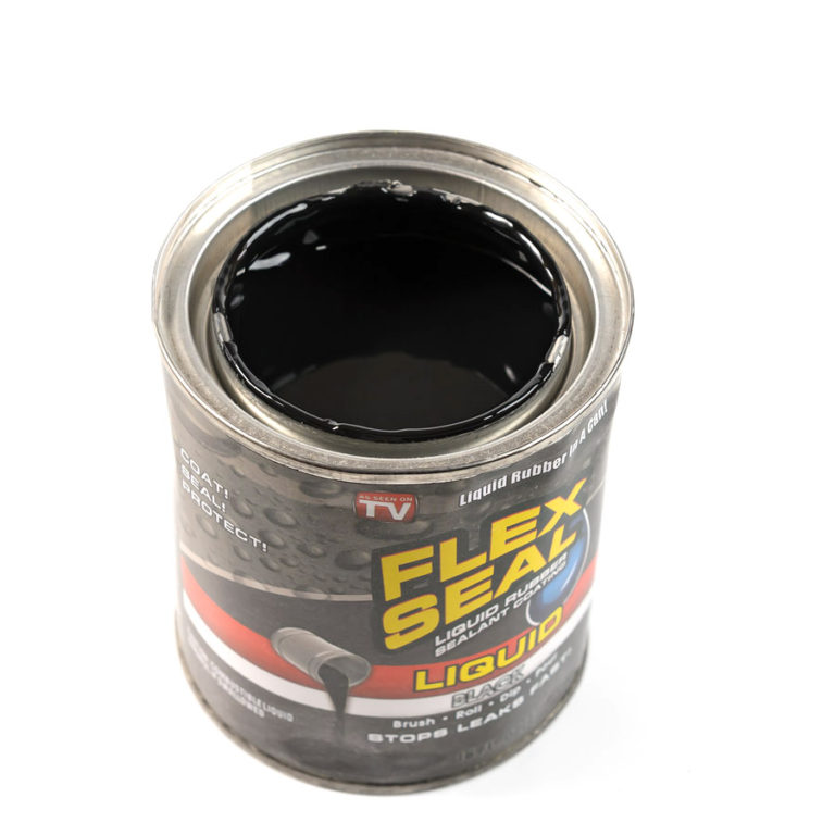 The vibrator head has a working part diameter of 114 and 133 mm. The number of oscillations is 5700 per minute.
Fig. 28. Deep vibrators
a - vibrator head; b - with a flexible shaft; c - with a planetary vibration element
Flexible shaft vibrators are used when concreting densely reinforced structures. From the electric motor (motor head), the rotation is transmitted by a gear to a flexible shaft protected by armor. A replaceable vibration tip is screwed into the threaded bushing, which is an eccentric shaft mounted in ball bearings. The vibrator is turned on by turning the handle of the electric motor switch. The number of oscillations is 6700 and 10,000 per minute, the diameter of the vibrotip is 51 and 76 mm.
A vibrator with a remote motor and a planetary vibrating element with internal unbalance rolling is shown in fig. 28, b. Rotation from the motor shaft is transmitted to a vertical shaft with couplings 16, allowing the lower part of the shaft 17 to deviate from the geometric axis by up to 5°.