Before wiring in new ATV or UTV accessories, you need to know how much of a power draw they will be and how much your machine can handle.
For many of us, after we buy that brand new (or at least new to us) Side-by-Side or ATV, we immediately start thinking about accessorizing it. We might pick up some awesome and helpful products, like a strong winch, radio, and huge LED light bar. While shopping for new off-road goodies is exciting, you need to first look at just how much power drain your electrical system handle.
Most off-road vehicles have a small reserve of power when being fully taxed electrically. This is for accessories and you must know what the percentage of available power is in order to prevent electrical problems. The stator is like the alternator on your car and runs off the crankshaft of most ATV/UTV engines.
To help you along your way, we’ve come up with a list of things to really pay attention to when wiring in ATV electrical accessories.
Lead photo courtesy Erlyani999/Shutterstock
Before you do any kind of work on your ATV or UTV, the most important tool you should have in your hand is a service manual. We really like the OEM manual when you can get your hands on one, but Clymer is an aftermarket brand that does a pretty darn good job of providing specs and walking you through repair processes.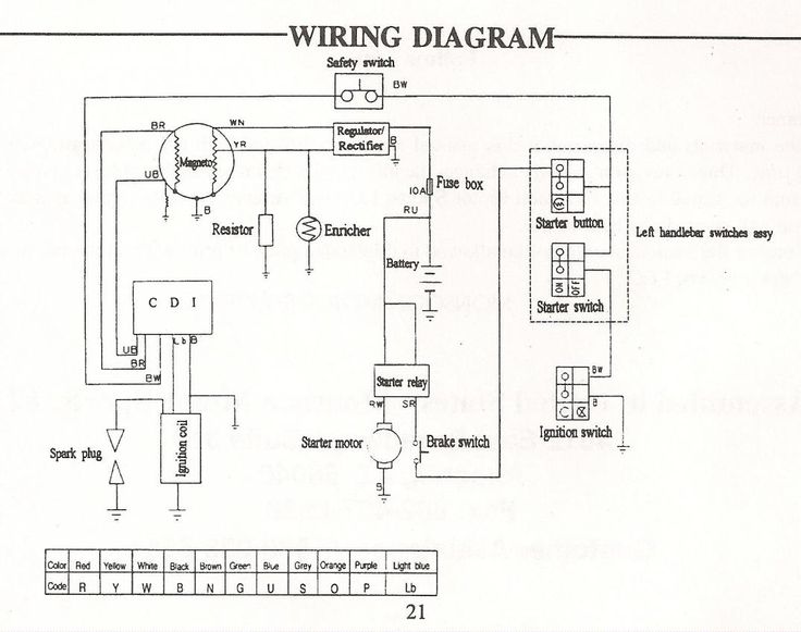
Why are we suggesting you get one before installing accessories into your ATV wiring? The manual will have critical information like how much power your ATV or UTV is capable of putting out, so you know just how many or how powerful the products you install can be. This one detail could mean the difference between a good working machine and new accessory or possibly the destruction of both.
Check Price
If you think you will be adding several electrical accessories, our number one suggestion is to to install a power block or hub. This gives you an all-in-one location that provides fused power distribution and ground locations in one convenient location. These power blocks or hubs are available with a wide number of terminal connections to cover any number of electrical accessories you want to add to your ATV wiring system. These style hubs are not water-tight, but they don’t really have to be as long as the terminals are covered.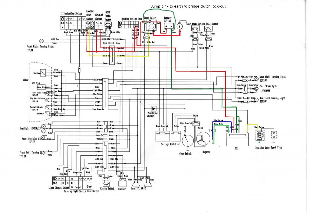
Check Price
If you take the time to read the installation instructions of the accessories you’re wanting to wire into your ATVs electrical system, most will provide a recommendation for wire size and length to use. For example, if you’re doing an ATV light bar install and it calls for 14 gauge wire to be used and you only use 16 gauge because it’s all you have. If you use that smaller gauge wire, it may not be capable of handling the amperage draw and get hot. This could potentially lead to the wire shielding starting to melt away leaving exposed wires and possible electrical shorts. Yeah, we’re talking about extreme situations here, but they’re totally possible
There are plenty of kits that offer a wide variety of wire sizes and colors for you to keep in your shop, and be sure to get the stuff that is flexible so you can wire it around your frame and other components.
Check Price
Having a good switch can make or break your ATV wiring job. Rocker switches are available in a variety of sizes and styles, the only thing that holds you back from the number of accessories you do with your ATV wiring is switch space. If you’re run power directly from the fuse block, through the switch and directly to your electrical accessory, you need to make sure that it’s capable of handling the amperage load, much like choosing the right wire size. For really heavy loads, you can run your accessory off of a relay that is activated by a rocker switch, which is a preferred way of getting the job done but requires more space and wire to mount the relay in a safe location.
A newer, cleaner and much more convenient way of switching multiple electrical accessories can be done by using a gang switch. These are similar to the power block previously mentioned, but taken to the next level of cool.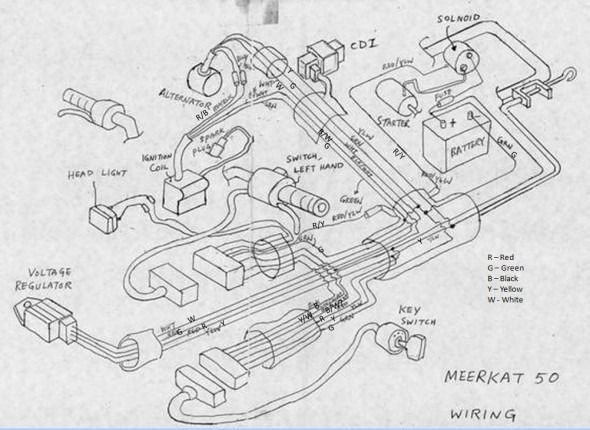 Most kits come with a heavy duty fuse or circuit breaker that you wire in between the battery and the control box. The control boxes come in numerous fused outlets that you wire your accessories to and are controlled by a small remote panel that is easily mounted on UTV dash panels or even a fender panel on an ATV.
Check Price
When you have to terminate or crimp on connectors to your ATV wiring, you want to make sure that you’re going to be using high quality, waterproof connectors. If you’ve never done any kind of electrical wiring before and don’t know the first thing about crimping wires, take some time to watch some videos on YouTube. You’d be surprised that there are much more than funny dog, cat and human trick videos on there. Having a good crimp can mean the difference between wires breaking loose and shorting out or staying where you need them to be.
If you have broken wires that need to be spliced back together, life has recently gotten much easier.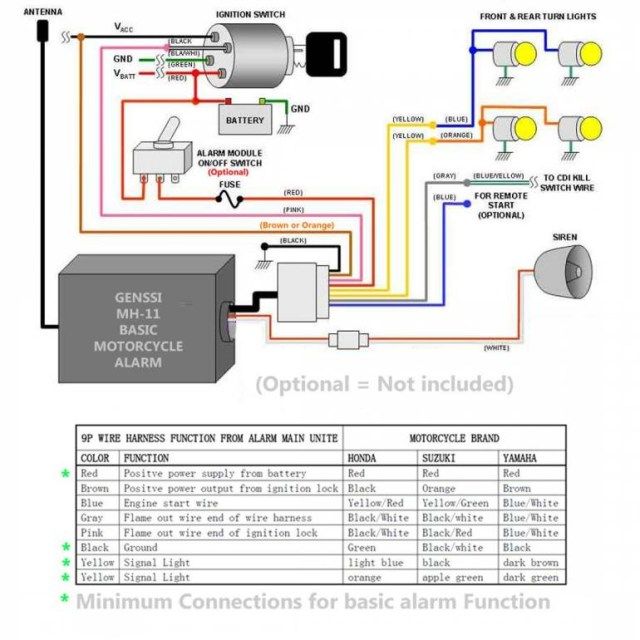 If you’re like some of our staff trying to use a solder gun to get wires back together, you can be left with a big ball of melted solder and a few strands of wire touching each other. There are some new solder seal wire connectors that not only solder the wires together with heat from a heat gun, but they also feature heat shrink tubing that seals off the ends from the elements. These are a must have in any DIY mechanics tool box.
Check Price
One of the most common mistakes or issues we see when adding 12 accessories to your ATV wiring, is that the wires are either not shielded or secured in place. While you may not have any issues with sloppy wiring, why take a chance? If you are going to add an expensive product like a light bar to your machine, why not take time to route the wires in the best possible way. Buying some wire shielding or loom to cover the mass of wires will not only keep the wires together and looking nice, but it prevents chaffing, which could lead to shorts and all kinds of other problems. Also, don’t be afraid to use a good handful of zip ties to secure the shielded or un shielded wires into place. The tighter you can keep the wires to your factory wiring loom or frame, the less chance there is for anything to protrude up from the ground and yank it apart.
Remember to read the directions for the electrical requirements for the product you are installing. Accessories like your winch require specific placement of the relay and some HID lights will not work without a good supply of power. We have had brand new lights flicker and never work again only to figure out later that the low voltage present burnt out an igniter or other part in the system.
Check Price
With so many options, it can come down to price and convenience. Unless you’ve already bought switches and switch panels, the best and easiest solution for power distribution to your accessories, is to use one of the gang switch options we discussed. These really take care of everything you need in one simple package. If you want to use traditional rocker switches, you’ll want to get a power hub that has a few more terminals than you need at the moment. This gives you the option of running additional accessories down the line. Some provide both power and ground terminals, but you can also get a hub that only has fused power in the event you just want to ground your accessory close by.
It really comes down to appearance and personal preference. You can go with some switches that are as small as a button, but the most common are the automotive style rocker switches. Many of these are pre-printed with common accessory images on them or you can even have custom ones made. The main thing you need to know is how much amperage that they can withstand if you’re not going to be using a relay to power your higher draw accessories.
Become an ATV. com insider. Get the latest news first by subscribing to our newsletter here.
We are committed to finding, researching, and recommending the best products. We earn commissions from purchases you make using the retail links in our product reviews. Learn more about how this works.
Updated 8/11/2021: Ranked product, added links to multiple products in each listing, added FAQ, added additional resources, updated product images
Home - Dirtbike - Dirtbike Features - ATV Electronics series: Part 1 - ignition systems
Few things can be as frustrating as diagnosing electrical systems. After all, there are seldom obvious signs of failure - I mean, you just can't see if electrons are flowing or not. Sure, every now and then you find a corroded connection, frayed wire, or burn looking electrical thingamajig. But how can you tell if your CDI or stator is bad? It's a real drag to have spent $100 or more on a new coil only to find that your safety tether had a bad connection. The key to effectively troubleshooting electrical systems is to have a solid understand of their operation. Only then can one efficiently narrow down what the faulty component is. To aid in that process, the technical folks at ORC have decided to put together a three-part "electrical systems" series to cover the three most basic systems of the typical ATV: ignition, charging, and starting. To kick off the series, the first installment handles the most important: ignition.
Of course, the primary purpose of the ignition system is to create a spark.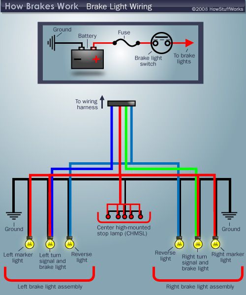 Years ago, a fellow named Kettering came up with a pretty good way to make a spark. Very basically, his invention consisted of two sets of finely wound copper wire - commonly referred to as the ignition "coil" -.that when powered with electricity on one winding would create a sudden jolt, or spark, of electricity on the other when the electrical power is interrupted. To keep up with a spinning engine, the electrical power is switched on and off via a contact switch that's controlled by a cam lobe driven by the engine. Pretty darn simple, and pretty darn easy to diagnose with basic tools. However, this conventional "breaker" or points-type ignition had reliability issues and was limited to low rpm applications. Enter the age of high tech electronics: integrated circuits, transistorized ignitions, and CDI.
 ..
..
The good news is that CDI, or capacitor discharge ignition, was all that points-type ignitions weren't - they had no moving or wearing parts, could produce a heck of a spark, and could run very high speed. Bad news is that the ignition system now became a "black box", both literally and metaphorically. No spark? Might as well start swapping parts until you the spark magically reappears. Not a bad proposition for a dealer that has parts sitting on the shelf he can try with no obligation. But to spend a hundred non-refundable dollars on simply a hunch is a tough pill to swallow.
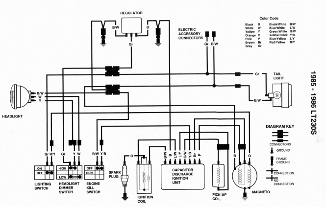
| Schematic of a typical CDI ignition system |
Fortunately, we can break down the operation of the CDI to some basic circuits - the guzzinta's and the guzzouta's (inputs and outputs). Whereas the points-type ignition has only two circuits (power and ground), the CDI has 5 primary circuits. On the guzzinta side we have the obligatory duo of power and ground, but with the added complexity of a circuit to tell the CDI when to fire (trigger circuit), and another to tell if to fire (kill circuit). What's left is the only circuit on the guzzouta side: the power to the ignition coil (fire circuit).
So let's discuss those circuits and their possible failure modes. The CDI's ground (DC negative) is always connected and provides the connection back to the engine's own voltage ground point or reference, which is the same reference the spark plug uses when creating a spark. The key piece of info here is that wherever the CDI makes its ground connection has to be essentially the same ground reference as the spark plug - make sure there's clean metal all the way between the two connection points, and virtually no resistance (ohms). If the CDI makes its ground connection at the frame up near the gas tank, be assured that the circuit from there is good all the way back the cylinder head. Don't rely on a ground connection through engine mounts. They can be intermittent, dirty, corroded, rubber-bushed, or painted. Proper grounding would dictate a ground strap from the engine directly to the wire harness.
Next thing we need is a way to power the CDI. Some CDI's are powered by 12vdc from the machine's electrical system, but most others generate the requisite electrical power from an exciter coil underneath the flywheel. As the magnet on the flywheel passes the exciter coil, electrical current is generated and in the case of a Capacitor Discharge Ignition or CDI, that charge is stored temporarily in a capacitor for a split second until the CDI is told to fire. Since the CDI is already tied to ground, there's only a single wire connecting the exciter coil to the CDI. To check this voltage produced by the exciter is tricky because it requires the engine to be turning. An electric starter can produce the necessary crank rotation, but diagnosis by means of kick starting is difficult since the output voltage varies with engine speed. To check, use a digital voltmeter (DVM) and set to AC scale. Connect one DVM lead to the exciter output wire, and the other to case ground. Most shop manuals will list a minimum AC voltage for both running and starting. Be CAREFUL when testing, the output from the exciter coil can reach 200 volts!
The power stored in the CDI's internal capacitor needs to be put to work, but the key to proper engine performance is doing it at the right time. That's where the pulse generator comes into play. Again, underneath the flywheel lies yet another magnet and coil combo, but the sole purpose of these two is to precisely identify to the CDI the position of the crankshaft. That is, it tells the brain box where the piston is and therefore when to fire. Basically, the CDI waits around for the pulse generator to tell it that the piston has just hit some point before TDC, and then waits the appropriate amount of time (dependent on rpm and spark advance) before energizing the guzzouta circuit that sends power to the well-recognized ignition coil. This circuit is diagnosed similarly to the exciter coil above, but instead connect your DVM to the pulse generator output. The voltage is much less and should be listed in your manual.
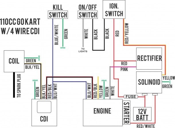
The last CDI circuit is the "kill circuit" which is how the CDI knows to quench the spark and kill the engine. Typically this circuit is switched to ground, and some CDI's require this circuit to be closed, while others require it to be open for engine shutdown. Most safety tethers, kill switches, and ignition switches utilize this circuit to control engine operation. The easiest way to troubleshoot a no-spark malfunction is to pull the spark plug and check for spark by unplugging this circuit. If no spark, then connect a ground wire directly between engine ground and this circuit (on the CDI box side). If still no spark, the problem is likely with another circuit.
To complete the whole ignition system, we still need to produce enough voltage to jump a spark across a 1mm gap, inside a running engine.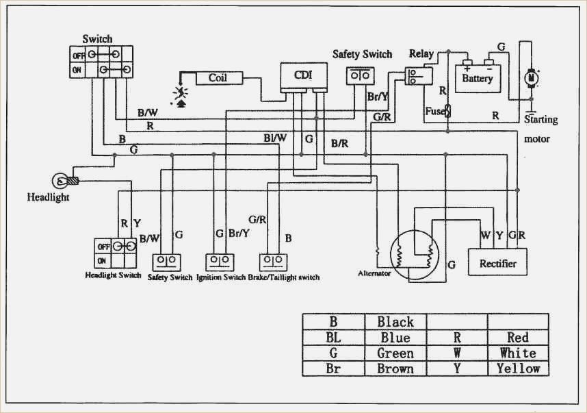 This part of the system hasn't changed much over the years - it's still a good ole ignition coil with a small wire going in, and fat one going out. It's a little different since we no longer have 12vdc going in, but rather nearly 10x that!. It also requires a good ground connection so insure that there's no corrosion, mud, or paint separating the mating connections. Although it's easy to blame coils for electrical problems since it's difficult to test (resistance checks are not always reliable), they are not commonly known to be failure prone. More likely is a bad spark plug cap or connection to the fat plug wire. With some coils passing as much as 60,000 volts make sure your plug wire and cap has no exposed breaks or possible leak paths that water can penetrate.
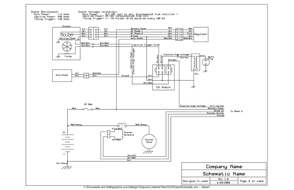 When the coil fires it will seek the path of least resistance, and if there's a way for 60,000 volts to get to ground easier than through a compressed air-fuel mixture (spark plug gap), it'll take it. And water does that job quite nicely.
Stay tuned, next month we'll get into the charging system of an ATV's electrical system.
Moscow:
1st Varshavsky proezd, 2s8
+7 499 500-97-34 Call me back
Page not found at given address.
Please go to the main page or use the site map.
08/15/2013
The article shows the standard electrical pinout.