If your ATV isn’t getting spark from the spark plugs at the engine, you’re basically dead in the water. This can be an extremely frustrating spot to be in because the engine won’t turn over and won’t give any hints as to why. I’ll tell you exactly how to check for spark on an ATV, and if you’re not getting any, how to diagnose the electrical components to find out exactly where your problem is.
To quickly tell if your ATV is getting spark, remove the spark plug from the engine. Reinsert the plug back into the coil wire. Hold the electrodes of the spark plug close to the engine to ground it, and try starting the engine. If you see spark coming from the end of the spark plug, your ATV engine is getting spark.
Keep in mind, on some models you will need to have the handle bar switch in the run position and the rear brake applied. Look for any other red buttons or kill switches that might have been pressed. A lot of quads have fail safes you need to think about when trying to start the engine.
If you have a hard time being able to tell if you can see a spark or not, you could always have a buddy hold the electrodes of the spark plug. If he yells when you try to start the engine, you have spark.
There are a few reasons an ATV won’t be getting spark from the spark plugs. The electrical systems on these quads can get a little tricky sometimes. Your best bet is to just check one thing at a time making your way down the list until you’ve found your problem.
The most common reason an ATV is getting no spark is a bad spark plug, either the wrong plug all together or just not gapped correctly. Or the spark plug just went bad, that happens quite often and it’s normal.
If you find out you need to replace the spark plug, you can usually find them easily on Amazon here: ATV Spark Plug.
If you know your spark plug is good and gapped correctly, then you’ll want to check for a loose wire, a bad switch, a bad connection, the ignition coil, or a problem with the stator. Lets go over how to check these one by one.
First, you’re gonna want to check the condition of the spark plug wire or ignition coil wire. This is the wire that hooks up to the spark plug when it is bolted into the engine. Sometimes these wear out because the wire itself is usually exposed to dirt, rocks, and debris while riding.
If the spark plug wire looks good, the next step is to check for bad connections or bad switches. To do this, disconnect the main electrical connector coming out of the engine. Doing this will unhook the kill switch, ignition switch, and all the wiring associated with those switches. Check to see if you get spark now.
If you got spark after unhooking the main electrical connector, then your problem is one of those switches or the wiring for one of those switches. Now your task is to go through and disconnect each switch one at a time to find the problem part. It will help to have an ohm meter to check each switch and each wire separately.
First off, you’re going to need a digital multi-meter to test the electrical components of your ATV. If you don’t know what that is, check out this Fluke 115 Compact True-RMS Digital Multimeter on Amazon. That’s the one I have and use, and I recommend it if you’re in the market for one.
You will also need basic tools to get the ignition coil on and off the machine. If you want to be extra safe, you could unplug the battery before starting. But I find it’s ok to just unplug the wiring to the ignition coil before removing it.
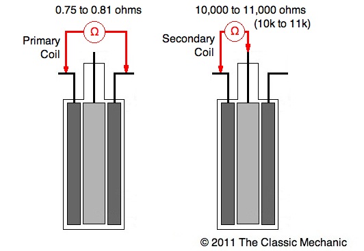
To locate the ignition coil, simply follow the wire connecting to your spark plug. Once you have the ignition coil out, you can hook your multi-meter up to it to begin testing. Start by testing the primary side of the ignition coil, where the ignition coil was wired, not the side that goes to the spark plug.
You should see between 0.2 and 5 ohms of resistance. That is a wide range because it varies from machine to machine. It’s best to look through your service manual to see what your ignition coil should read on its primary.
Next lets test the secondary side of the ignition coil. This is the side with the spark plug caps. If your ignition coil has two spark plug caps, simply put the red test lead in one and the black in the other. Look for around 16k ohms resistance, but again you should check your service manual for your specific measurements.
If you only have one spark plug cap, you will take one multi-meter lead and connect to the spark plug cap and the other to the primary side power connector.
Use the spark plug cap as if it’s the negative side of the primary for this test with that type of ignition coil.
Again you will need a multi-meter and basic hand tools to remove the stator. You either have a single phase or a three phase stator. Three phase is the most common, and probably the type you have.
To make sure, check the wiring harness coming from your stator, If you see group of three wires of the same color (usually white, yellow, or black) you have a three phase stator. A single phase stator will not have that set of three wires.
To start with the three phase stator, set your multi-meter up for ohms. Now get the connector with those three same colored wires we talked about before. You are going to be testing each of those wires against each other. So leg one vs leg two, leg two vs leg three, and leg three vs leg one.
You can do this by simply inserting the multi-meter leads into the connector. You should typically see between 0.1 – 1 ohms for each measurement. But check your service manual for your specs on your machine.
If your meter reads OL, that stands for open line, and you will need a new stator. To check if your stator is shorting to ground, simply hook one lead to a stator leg (through the connector) and the other to the stator body or chassis ground on your machine. You should not get any reading on your meter. If you do get a reading on any of the legs, you will need to replace your stator.
You can do this testing while the stator is still on the machine if you’re able to access it. I find it easier to remove the stator to do the actual testing, but that can be a pain all on its own.
That’s it for the most common electrical problems you’ll see with your ATV. It’s usually something like a bad kill switch or loose wire or connection. Hopefully you find your issue with out too much trouble.
Electrical problems can be some of the most time consuming. If you have the money to spare, it may be worth it to just bring your machine to a shop if you don’t feel like messing around with all the potential causes.
Even then, it doesn’t hurt to quickly look over some connections before calling in a professional.
Sharing is caring!
So you’ve established that your ATV doesn’t have a spark or only has a weak spark. But now what?
Troubleshooting an ATV with no spark can be quite challenging and mildly frustrating, but it doesn’t have to be. That’s why I’ve made this simple step-by-step guide to help you identify why your bike is acting up.
Page Contents
Your bike’s ignition system consists of various components that work together to create a spark. Each component in the system is just as important as the other. They all have to function correctly, or there will be no spark or the spark will become weak.
When your ATV is not getting a spark, the problem is with one or more of these electrical components:
The easiest way of identifying which of the listed components is failing is through a process of elimination.
With electrical issues, it is always better to check the most straightforward stuff first. If you assume the worst and you begin by removing the stator, you may end up having to reassemble a bunch of components you didn’t have to take apart.
More often than not, you will find that there is a problem with the spark plug, the kill switch, a wire, or a connector.
By performing various tests, you should be able to pinpoint which component is faulty. Before you’ve established which part is acting up, there is no need to focus on one single component.
You may or may not already have done this step, but you need to verify that the ATV actually has no spark before you continue troubleshooting.
While you may feel confident that a lack of spark is the issue, keep in mind that other starting issues could be causing similar symptoms. Therefore it’s not enough to assume the spark is not there; you need to test it.
An ATV needs fuel, air, and spark to start and. If you are not sure whether your bike not starting is caused by a lack of spark, or something else, we recommend you read this guide.
 This will ground the spark plug so that it can create a spark.
 Alternatively, you can test the spark plug by using a cheap spark plug tester. Spark plug testers come in various styles, but here are two of the most common.
With the first spark plug tester style, you place the tool’s grooved part over the spark plug wire while the engine is running. The bulb inside the tool will flash to indicate a spark and how powerful and consistent it is.
Pen-style spark plug tester.The second style of tester connects where the spark plug normally would be. Remove the spark plug boot from the spark plug and connect it to the tool. The tool has an alligator clip that connects to ground, such as the engine or an exposed metal part of the frame.
If there is a spark, it will appear inside the see-through tool casing, jumping between the tho metal leads. If the spark is good, it will have a regular purple-blue color. If the spark is weak, the spark inside the tool will appear with yellow-red and a more inconsistent spark pattern.
Now that you have verified there is no spark; it’s time to begin the actual troubleshooting.
The ATV will not create a spark when the kill switch is off. However silly it may seem, you’d be surprised how often people forget to turn it on before attempting to start their ATV.
ATVs with electrical starter motors won’t even crank the engine if the kill switch is off. So if the engine will crank, you know that the issue is likely not with the kill switch.
Pull start or kick start ATVs, on the other hand, is another story. No matter how much So make sure the switch is turned on before you end up pulling until you’ve wet fouled the spark plug.
While some ATVs will run without a battery, others need a healthy battery to power the ECM (electric control module) and the electric fuel pump. The ECM is a small computer that tells the ignition coil when to create a spark.
If the battery holds an insufficient charge, the ECM may not power up, and therefore will not tell the ignition coil to create a spark.
Read the battery voltage by setting your multimeter to DC volts, place the red lead to the positive battery terminal and the black lead to the negative terminal. A healthy battery should read 12.45volts or more when fully charged.
If you want to learn how to charge your battery correctly, please head over to this guide.
To test battery ground, you should place black lead to the engine block or an exposed metal part of the frame. The red lead goes to the positive battery terminal. If the battery ground connector is good, you should get a reading close to or identical with the one you got when testing directly to the battery.
If you get a reading that indicates bad ground, make sure the main engine ground is properly fastened and has not corroded. You find it by tracing the big black wire coming from the battery.
Spark plugs are cheap and easy to replace. They are considered consumables that may go bad for no apparent reason.
Be careful not to crank the engine for too long before checking the plug, or youøss risk overheating and possibly damage the starter motor.
Whether the spark plug gapping is incorrect, the plug has gone bad, or it’s the wrong plug altogether for your engine, it may no longer be able to provide a spark. Note that a spark plug may physically look fine but still have gone bad.
The easiest way of testing if a bad plug is the issue is by replacing it with a new one and then test for spark as described above. You don’t even have to remove the old plug. Just pull off the bott, insert a new plug, and test for spark.
If your new spark plug isn’t creating a spark either, you know the problem is not with the actual spark plug.
A bad electrical connection in a connector may prevent the ignition system from working as it should. Ensure all connectors in the ignition system wiring harness are not damaged from corrosion, are not full of dirt, and are properly connected.
Check all connectors, especially the ones that connect the kill switch or ignition key.
Now test if this has fixed your no-spark issue.
If a wire gets damaged, exposing the metal leads, you may get a short to ground. Trace all the wires connecting the various components of the ignition system. If you find a damaged wire, repair or replace it.
If the kill switch internals fails, it may stay off even when in the “on” or “run” position.
You can test the switch by performing a continuity test using a multimeter, a test light, or a simple continuity tester.
Insert one probe into each of the two cables going into the switch. There should be no continuity when the switch is off and continuity when it is on.
Alternatively, you can do this simple test:
If your ATV has a 5-pin CDI-box, you can use it to identify a safety switch issue. This test only works on 5-pin CDIs, typically found on cheaper Chinese youth ATV models or older ATVs.
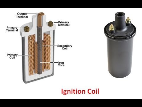
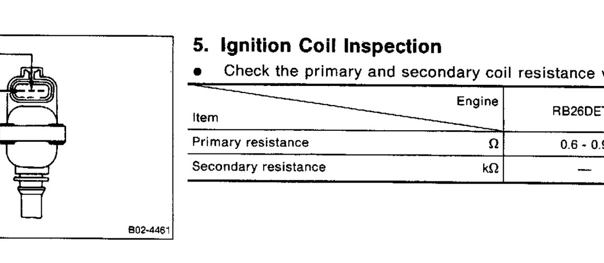
The ignition coil generates the electrical pulses of current sent to the spark plug to create a spark.

With a multimeter, you can read the ohms resistance of the primary side and the secondary side of the ignition coil. Each of these readings can tell you whether the coil is ok or not.
Test the primary side:
 Refer to your ATV service manual for the exact value for your bike. If you get a reading outside this range, the ignition coil is likely bad and needs replacing.
 Test the secondary side:
 Check the CDI or ECU
While modern ATVs nowadays have ECM/ECU, many cheaper Chinese youth ATVs and older ATVs use 5-pin CDI boxes to control the spark.
There aren’t any good ways of testing these boxes at home. A CDI is relatively cheap, so your best bet is to replace it and try again.
ECU’s, on the other hand, are more expensive. You’re likely better off testing or replacing both your ignition coil or stator before possibly replacing the ECU at last.
The stator is what creates the electricity on your ATV. It is located behind an engine cover, but luckily you can test it without removing it.
There are two main ways you can test the stator. A static test, where you test internal resistance when the bike is turned off, and a dynamic test, where you read voltage while the engine is running.
If the stator fails any of the tests, you may have a defective exciter coil inside the stator, and the stator needs to be replaced.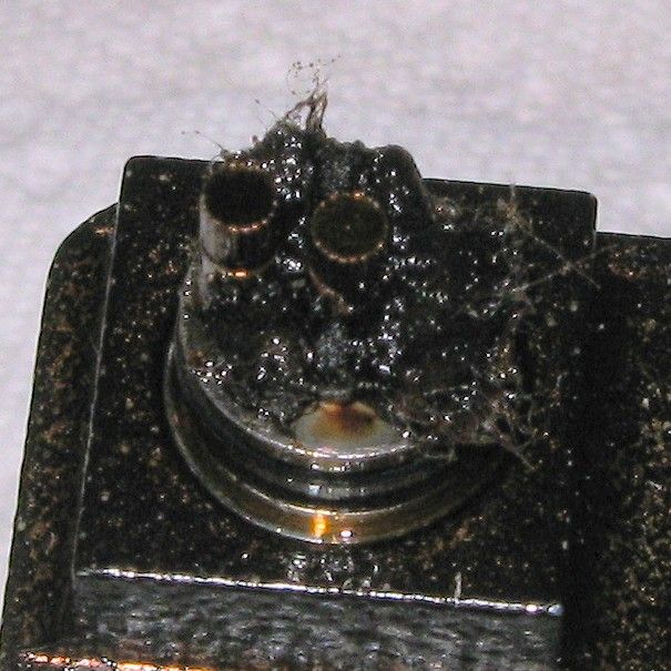
The crankshaft position sensor (CKP-sensor) registers and tells the engine exactly where the piston is as it moves up and down. This information is necessary for the CDI or ECU to say to the ignition coil when to power the spark plug.
The CKP sensor is either built into the stator assembly or located separately on the engine.
Look for damaged wires going to the sensor or a cracked or bent sensor bracket if you have a separately located sensor.
You can test the sensor by using your multimeter to measure its resistance:
To buy a reliable scooter that will last more than one year, you need to carefully check its components and systems.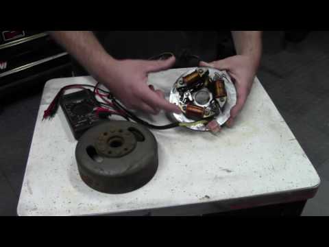 And it's worth starting with the ignition. This system converts the current, supplies it to the spark plug and ignites the fuel mixture. The action is carried out in several stages, and even the slightest failure can affect the operation of the engine and increase fuel consumption. Therefore, let's figure out how to check the ignition on a scooter.
The first thing to do is to check the lock itself. The assembly will need to be repaired if:
Figuring out how to check the ignition switch on a scooter is pretty easy. You just need to turn the key a few times and start the device. But it is worth remembering that this is the simplest breakdown, and to fix it, you just need to change the lock.
The ignition coil of a scooter is responsible for sparking, and its failure will make it impossible to start the engine. If you find that the candle does not give out a spark, first of all, diagnose this node.
To perform the test, you will need a multimeter that can measure resistance. It is best to use an electronic device, as it is more accurate.
To carry out diagnostics you need:

The coil can also be 'ringed' with an ordinary indicator screwdriver. With it, you can check the candle cap, primary and secondary winding. However, this is a "field" method that does not allow to identify all defects. If you need an accurate check of the scooter ignition coil, then a multimeter is indispensable
When checking the ignition of a 4t and 2t scooter, it is also recommended to inspect the spark plug and its cap. First of all, determine the type of candle. There are two types of element: cold and hot. The scooter documentation indicates which type of candles should be used. But if the component is chosen incorrectly, then:
If the spark plug is chosen correctly, the color of its electrode should be light brown. Any abnormality is indicative of component wear or other systems on the scooter not working properly. For example, if the fuel mixture is poor, then the electrode will be white, and if the composition is too rich, a velvet deposit will form on the candle.
But to check the candle cap, you will need additional equipment - a multimeter. Set the device to 20 kOhm, and then connect the probes to the input and contact. The resistance in the working component ranges from 2.5 to 5 kOhm. But if the indicators are higher, then the cap is faulty.
The switch is a key element of the ignition system, which is responsible for the accumulation of energy, and its timely supply to the coil. If the component is defective, then the scooter will not start, the motor will stall or run erratically. But in order to accurately determine the source of the problem, you need to check the scooter ignition coil switch for serviceability.
To do this:
If it is not possible to check the ignition coil and switch of the scooter with a multimeter, you should simply replace them with good parts and retest the system.
The sparking process must take seconds, so every ignition part must function correctly. This means that any defective or worn components will have to be replaced. Even a minor breakdown will disrupt the operation of the engine and prevent the engine from starting.
So, when buying a scooter, it is necessary to check the 4t scooter ignition coil with a multimeter, inspect the spark plugs and wiring, test the switch and evaluate the condition of the ignition switch. Such a small diagnosis will help to significantly save on further maintenance of the moped.
08/14/2020 11627
0091 when starting with an electric starter, the engine does not start, but at the same time, starts from a manual kick. The reason lies in the banal discharge of the battery. Such is the peculiarity of CDI ignition (especially Chinese and especially Kazumovsky) that sometimes the battery energy is even more than enough to confidently crank the crankshaft, but there are no flashes in the cylinder. The reason is that at the moment of starting there is a voltage drop, there is not enough energy to charge the CDI capacitor and there is no spark, or it is very weak. At the same time, many are confused by the fact that when checking "in air" there is a spark, but in a cylinder under pressure, where the conditions for sparking are much worse, there is no longer a spark and, accordingly. there is no start even though there is some kind of spark during the check. In such a situation, you just need to charge the battery!
Poor contact in the flat connector of the ignition coil can also lead to symptoms similar to malfunctions in the operation of the carburetor (failure when pressing the gas, the possibility of the engine running only at idle, pops in the exhaust pipe). It is treated simply by crimping the terminal (or even better, replacing the terminal with a more rigid one), I recommend that you carry out the procedure at the stage of preparation for operation, because in the event of such a malfunction, it is floating in nature, similar in symptoms to other breakdowns possible for the Otto internal combustion engine, and it can get out at the most inopportune moment. Starting around mid-2011, the terminal was replaced with a more reliable connection.
If, despite the crimping of the terminal, symptoms of late ignition appear (smell of gasoline from the exhaust, pops in the muffler when the gas is released), then it is necessary to check if metal particles have adhered to the inductive spark moment sensor . Since the sensor is located under the same cover with the bendix and the flywheel gear, the chips from these parts stick to the sensor with magnetic properties, as a result of which the signal front is knocked down, the CDI unit incorrectly determines the TDC and engine speed, which leads to errors during sparking. I repeat, the symptoms will be similar to a malfunctioning carburetor and an excessively rich mixture (incomplete combustion of fuel, a strong smell of gasoline from the exhaust, pops in the muffler when releasing gas). As I already wrote, with such signs, the fuel line should be returned, and if this does not help, leave the carburetor alone and check the ignition system! But first of all, we look at the sensor and clean it from adhering metal particles (for example, using adhesive tape).
Ignition switch (CDI control unit)
The CDI unit can "burn out" (completely fail) for two reasons. Firstly, due to the unstable operation of the standard voltage regulator.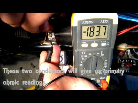 It is better to replace it with a similar part from Dinli or CFMOTO (by soldering the connector). Secondly, if you mix up the battery terminals. Of course, we are talking about a charged battery (if the battery is dead, then there is nothing to burn the electronics from). To avoid burnout due to reverse polarity, you can supplement the power supply circuit of the CDI unit with a diode. It is strange that this is not done by the manufacturer (although this may not have been done on purpose - to sell CDI blocks to inattentive 500K owners). Well, only replacing it with a quality one can save you from the poor performance of the voltage regulator.
If the spark has disappeared, I recommend the following algorithm of actions developed by experience and tested by time.
First things first quick test of the ignition unit. You need to check if the wire going from the block to the coil is sitting on the ground. To do this, disconnect the wire from the coil (if it is with a terminal) or disconnect the coil from the ground (to do this, you need to remove it) and check if it is closed to ground (with a tester or simply with a probe lamp).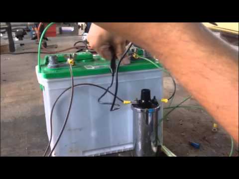 If it is closed, then the ignition unit must be replaced. If not (although it will probably be “yes”), then we continue the check.
It should be noted that the ignition coil, the spark moment sensor and the candle fail so rarely that it is unlikely that anyone will need the information contained below, but, nevertheless, I will write it down, since anything can happen on Kazuma.
Just in case, we change the candle to a known good one (preferably a new one). It is clear that it most likely will not help (unless the candle has traveled many thousands of kilometers), but it will eliminate doubts, and also allow you to check other components as reliably as possible. In this case, in no case should the ignition be allowed to work without load (check the breakdown for mass) - spark test is carried out exclusively with a cap of high-voltage wire dressed on a well-grounded spark plug.
Ignition coil, wire and spark plug cap
Next, check the coil, wire and spark plug cap.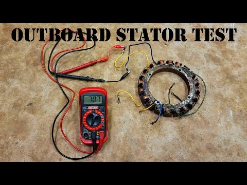
The high-voltage wire is attached to the coil using a screw poured into its body (on which it is screwed with its central part, which fixes the wire and also allows you to transfer the discharge from the screw to the current-carrying core). To check, you can unscrew the wire from the coil and measure the resistance. It should be at the level of 5 kOhm (5.000 Ohm), which will give the resistor in the cap. The wire is also screwed into the cap on the screw, the red sheath is just a sealant, inside there is a hard tip with a resistor. If the wire is in order, go to the coil. The resistance of the secondary winding should be 6 kOhm (6.000 Ohm), we measure between the high-voltage output of the coil (in our case, a screw) and the mass (“ears” with which the coil is attached to the frame and to which the ring terminal of the green wire is attached). In principle, you can check both the wire and the primary winding at the same time: if you do not remove the wire from the coil, then the resistance between the mass of the coil and the candle cap should be about 11 kOhm (11.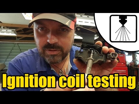 000 Ohm). The resistance of the primary winding should be no more than 0.3-0.4 Ohm (tenths of an Ohm!), We measure between the flat terminal (to which a positive impulse from the switch comes through the yellow-black wire) and the mass of the coil. The parameters are checked on two serviceable coils. If the data of the coil being tested does not match the above, the coil should be replaced, even if it produces some kind of spark. Under pressure in the cylinder, the conditions for sparking are worse than in air (at atmospheric pressure), and there may no longer be a spark, or the spark will be unstable and insufficient for normal ignition of the mixture. The ignition coil can be replaced not only with the original one, but also with a suitable one from other quadras (for example, Hisun, etc.), as well as with a car one (see below for connecting the latter).
In case of failure of the ignition coil , you can install an automotive one, for example, from a VAZ 2108-09 (or from a non-contact ignition system of any other car).
We buy a coil for VAZ 2108-09 and the most common wires (come in a set, 5 pieces, red) - with a copper core. No “silicone” ones - they have a high-resistance carbon fiber current-carrying conductor, CDI ignition will be difficult to handle, and most importantly, there is no point in overpaying 10-20 times for unnecessary things.
We take the central wire (which the basin should go from the coil to the distributor), cut off one end. We take our coil with wire and unscrew the wire from it. We connect the current-carrying cores of the VAZ wire and the 500K wire by soldering, reliably insulate (using heat shrink), and also, if possible, put a corrugation on the entire resulting cable, which we wrap with electrical tape (or again we wrap it with heat shrink) so that the BB cable does not lie anywhere directly with its insulation on the mass .
We connect the coil terminal going to the VAZ to the switch (K) with a negative wire (500K green with a ring terminal), the coil terminal going to the battery (B or just +) from the VAZ, we connect it to the output of the switch, which supplies the voltage of the capacitor to the coil (yellow-black wire coming to the coil, until mid-2011 - with a flat terminal).
It must be connected in this way, because in the CDI system the coil does not work as an energy storage device (unlike the "car" ignition system), but only performs the function of voltage transformation. That is: the coil must constantly sit on the ground, and when an impulse from the switch passes through it, it will simply give out a high voltage discharge to the candle (unlike the “car” connection, where voltage is constantly applied to the coil, and a spark occurs at the time of landing coils to ground).
Sparking moment sensor
If the part of the ignition system located after the CDI switch is fully functional, it is necessary to check the ignition moment sensor (crankshaft position sensor) for an open or short circuit of the winding:
The sensor can be checked indiscriminately with a tester! The working resistance is 110-130 ohms, you need to measure on the wires that fit the switch blue / white (blue comes out of the magneto) and violet (green comes out of the magneto)!
If the sensor is faulty, then you can put a suitable mount from any scooter (150-200 rubles).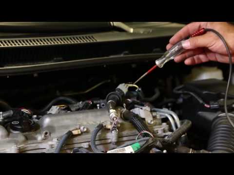 The original sensor is sold only complete with a magneto (3500-4000 rubles and more).
Again about the switch
With a good sensor, the ignition switch remains again (a new one costs about 2000-3000 rubles). It is possible to install a switch from a Suzuki Lets scooter, you just need to solder the connector, however, the used AlekseyL (see the report at the link above) is very difficult to find the block version (with an external connector) (at least I didn’t succeed), and when installing another modification (common, with a connector filled into the body), the ignition turns out to be extremely early (there are back blows to the piston). It may be possible to coordinate the operation of our sensor and the common CDI unit from Let's, but I decided not to risk it by choosing the sparking time by touch, but set it to 500K transistorized ignition with microprocessor control , for a report on the installation of one of the possible options for such an ignition system, see HERE.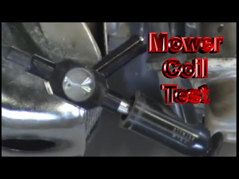
The best option is to replace the ignition unit with a design unit Grishko Alexander : it does not require either replacing the sensor or installing a car switch (discussion HERE). He himself took part in the tests. I recommend!
Report AlekseyL about this ignition system, see HERE.
Just in case, I additionally give a description of the pinout of the original ignition control unit and the image of the connector (cut off in the photo):
AlekseyL wrote:
If anyone is interested, here is the pinout of the switch connector:
Pinout from left to right, connector key at the bottom!
1 - sensor (blue wire)
2 - jammer (white / black wire)
3 - minus (black wire)
4 - ignition coil (orange wire)
5 - sensor (green wire)
6 - plus (red wire)
Please note that the colors of the wires in the switch connector change to others.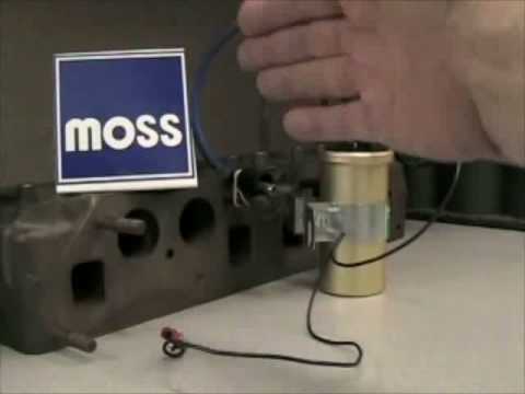 For example, position “4” - an orange wire goes from the switch to the connector to the coil, but yellow wire with a black stripe (etc.) comes to the coil from the connector, be careful!
For clarity, I also give a photo of the ignition harness connector (from the wiring side): However, it is possible to shift the COP by several degrees. To do this, you will have to remove the flywheel (and it is removed very reluctantly, it is not removed at all with ordinary three-legged pullers), unscrew the screws securing the platform on which the “stuffing” of the magneto sits and try to tear off the platform from the engine housing (planted on sealant). Now, by turning the platform within the slots for the mounting bolts, you can slightly shift the sensor relative to the flywheel: if you turn it counterclockwise, the ignition will become earlier, if clockwise - later. However, such an adjustment allows you to move the sensor at very small angles, which will not lead to any noticeable changes in operation.