via
Related Question
The best cutting tool to use for a tire is a utility knife or a retractable box cutter. It'll do the best job of cutting through the thick tire rubber. via
via
Once your tire is hanging in place, fill the bottom with topsoil. Then, plant your flowers and your hanging tire planter is ready! Also, see this guide for making a hanging planter. via
Yes, it is quite possible to pop a tire with a knife in some cases, but absolute care must be taken to ensure that the tire does not blow in your face. And after several cuts, push the knife into the tire at an angle. A cut deep enough through the sidewall of the tire will start to release the air in it. via
via
I've found those that do best in the tire are the plants that like being grown in warm soil – such as tomatoes, sweet potatoes, and peppers. Try to avoid cold-hardy crops in the tire, especially if you plan on keeping it the original black color (it will absorb the heat). via
Are old tires safe to use as planters?
Long-term, no, because the tire rubber will slowly biodegrade and release zinc, carcinogenic PAHs (polycyclic aromatic hydrocarbons) and other toxic compounds into your garden soil.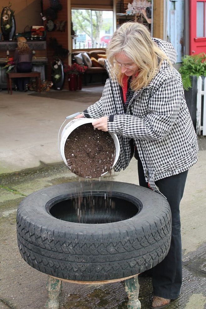 via
via
via
Old tires can be turned into fuel, paving material, mulch and more at tire recycling centers. If you have a stash of tires you need to get rid of, these facilities are a good option for you. via
The color of plant pots is important because it can play a role in how much heat the pots will retain. Dark-colored pots will absorb more sunlight and retain heat longer than light-colored ones. The color you choose should depend on the climate conditions in your area. via
You'll still need to line the planter box with plastic.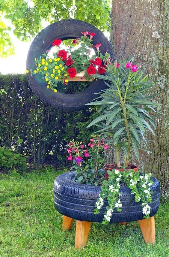 This helps protect the planter material from the water that drains out of the plastic pot. Using a plastic pot inside the planter box will help you plant new seedlings with ease. via
Tires contain aluminum, cadmium, chromium, copper, iron, magnesium, manganese, molybdenum, selenium, and sulfur, as well as a high level of zinc. As tires breakdown, these toxic substances leach out, contaminating the soil, the plants, and leaching through storm water into creeks and lakes. via
It should be very sharp but strong enough that it will not bend. As sharp as this but diameter is too small. This diameter is big enough but the screw driver needs alot of work. via
Yes, your comprehensive coverage will cover three slashed tires
, or any amount of slashed tires, whether it is one or four. It is a popular misconception that insurance companies won't cover three slashed tires, that it would have to be all four for the car owner to file a claim.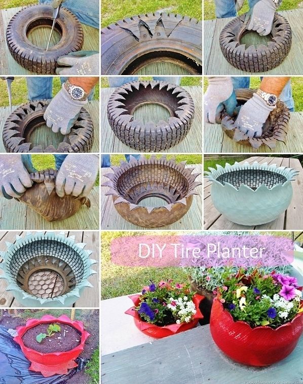 via
via
In order to slash a tire quickly, you need to use a sharp knife instead of a usual household one. A knife can very easily poke the rubber surface if applied with adequate force. A true knife slash will render the tire flat in a matter of seconds. via
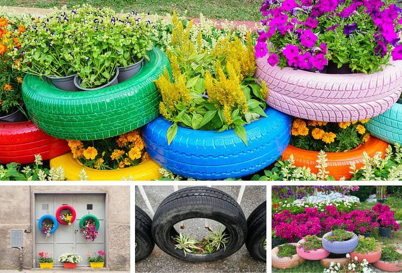
What to do with recycled tires? Tires are actually the perfect size to use as a planter in your garden. This guide teaches you how to make both simple and inside out DIY painted tire planters. All of your questions will be addressed. From sourcing tires, painting them, and making a planter, you will find plenty of inspiration to get your creativity flowing.
Table of Contents
Please note – you don’t have to paint your tires.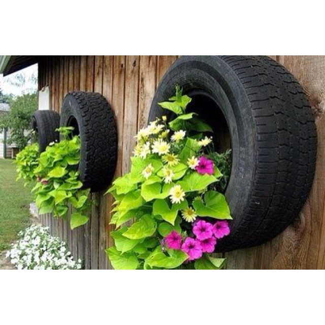 The non painted planters also look great when done right!
Regardless of the size of your yard, there are many ways to fit a tire. This guide will provide you with a wide range of ideas for all sizes and budgets. Lots of tips and tricks will be shared to successfully make your DIY planter.
Learn to make a Simple Tire Planter. Using car or tractor tires is the most common way to make one. Find out where to get used tires, what paint works best, and how to construct your own. We also answer questions you might have about health risks when using tires in your garden.
Learn to build an Inside Out Tire Planters. They are a fun twist on the classic style. We will get into detail about how to make these and any equipment you might require.
Build a DIY Tire Vegetable Garden. It’s a great way to get extra use from your planter. Use the tires to make raised beds and to keep your crops separate.
Jump to Ideas and Inspiration – 70 beautiful photos and ideas for your project have been gathered so that you can deck out your planter.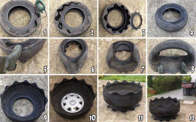
Jump to Creative Tire Planters that are anything but ordinary add a nice touch. Read on for ideas like how to turn your tire into a teacup planter!
Tires can be used in an assortment of ways to make the best planter for your needs. Be it a single tire with one large plant, many tires stacked together, or even a hanging tire, the options are endless! Let’s take a step back from the final product and answer some common questions.
For the DIY projects we will explain, the best tires to use are those from cars, tractors, ATVs, and motorcycles. Keep in mind what your purpose is when choosing a tire.
The easiest recycled tires to access are your own. Most tire shops sell used tires at reduced prices, and if you don’t need road safe tires they might have some to give away. If you live in a big city, search for a tire dump or junkyard.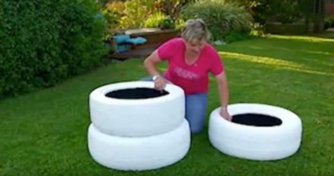 Since tires are hard and expensive to dispose of, chances are you will be able to take as many as you like at no cost.
As well don’t underestimate online platforms such as Facebook and Craigslist. One person’s garbage is another person’s treasure, or tire planter! Keep in mind that worn tires will work best as they will be easier to cut and maneuver into shapes.
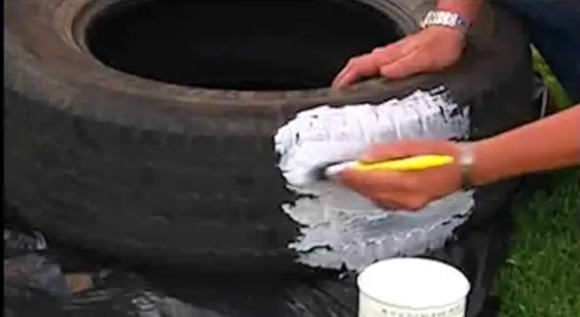
It is not necessary to paint your tire but it is a great way to add a splash of color to your garden, especially when your flowers aren’t in full bloom! If you choose not to paint your tire, note that black rubber will absorb far more sunlight and can get quite warm.
Before you begin to paint, hose down your tires to remove any dirt or dust. Once they are dry, the paint should have no problem sticking. For maximum results, use a white primer appropriate for rubber as a base coat. This will also make it easier to layer on a lighter color. Some spray paints will have a primer included in the product so double-check what kind of paint you have.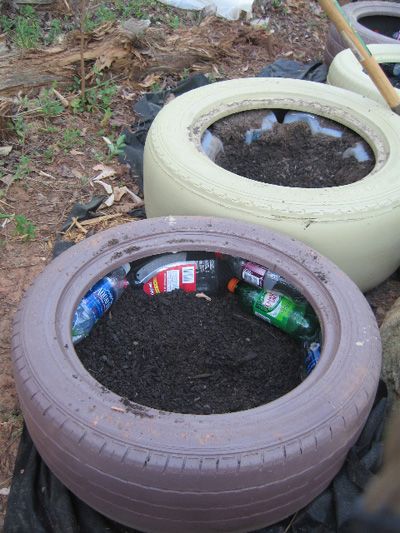
When choosing the paint, make sure to choose a non-toxic outdoor paint. Materials for industrial and marine use will be durable, but any outdoor latex or acrylic paint will work.
While you can use large brushes to paint your tire, spray cans are the easiest way to spread the paint evenly. When deciding on a color to paint, think about where you will be placing your tire and whether it matters if it heats up in the sun. For warm locations and delicate plants, lighter colors are the best option to keep the temperature of the soil consistent.
You can use acrylic paint as long as it is made for exterior use as your tire will constantly be faced with the elements. Regular acrylic paint is not entirely waterproof and requires a sealant. Keep it simple and avoid the extra step by purchasing paint meant for outdoor use. While acrylic paints can be more expensive, they maintain greater flexibility when they dry, making them more resistant to cracks and flaking over time.
Once your tire is painted you are one step closer to having a nice looking planter. Decide whether you want a single tire in a permanent location, stacked tires, or a raised tire planter. Depending on your choice, you will want to put something on the bottom of the tire.
If you plan to leave your planter in a fixed spot where there is already earth, you do not need to put anything in the bottom. If the planter will remain in a spot with no earth beneath it, you can place some straw or cardboard at the bottom before adding dirt. Poke some holes in the cardboard to ensure airflow and water drainage.
If you plan to stack multiple tires to make raised beds, you will need to have a sturdier base. A plywood plank cut into a circle and drilled to the tire is a good option for a secure foundation. Once again drill holes into the plywood so that water does not accumulate. If you plant to stack many tires, it is a good idea to screw them together to avoid accidents.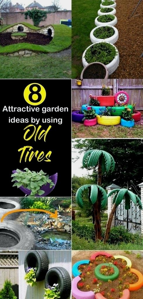
Now that we’ve looked at some common questions about appropriate materials, it’s time to dive into this DIY project.
The first thing to do is to get a tire for your project from one of the options suggested above. Clean your tire properly, and make sure it is dry before you start to paint. If needed, use a primer. Once the primer is dry, paint the tire with your preferred color. Feel free to add patterns and designs.
Decide if you want your planter to be in a permanent spot on the ground or if you want to raise it on a platform. The advantage of a platform is that you can move the planter around as you please. If you use a platform place a layer of cardboard or plastic with holes so that water can drain out.
Next, simply add soil and decide what you will plant in your new planter!
For an extensive description with photos of each step, check out this great guide.
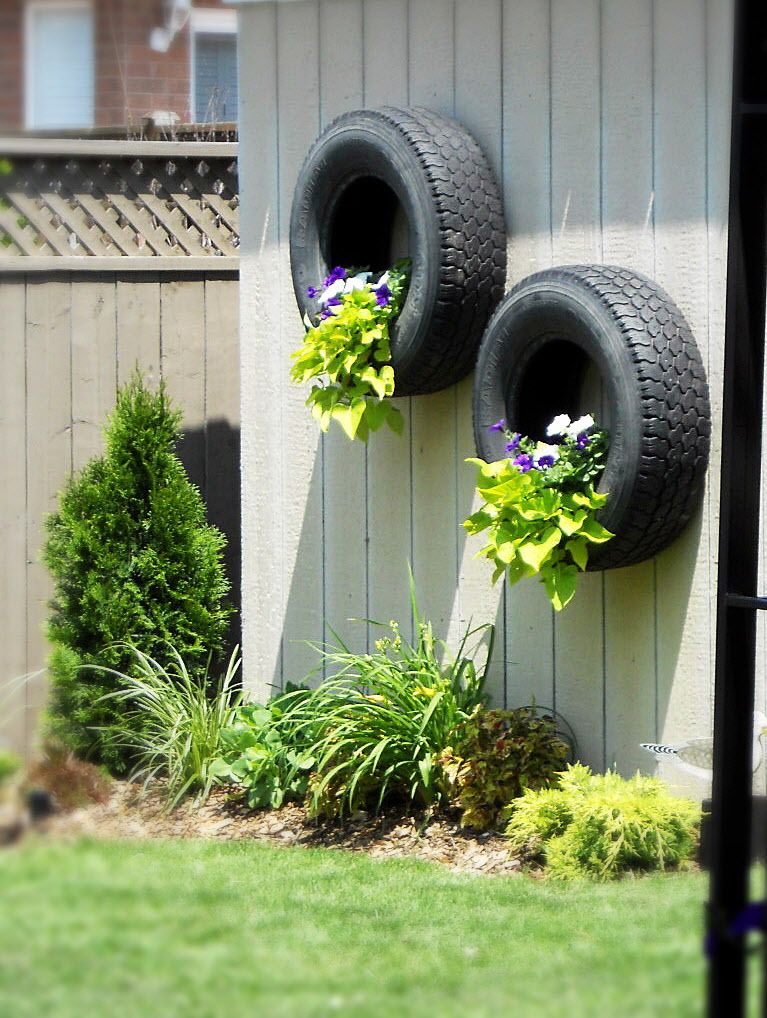
Now that we’ve gone through how to make a basic planter, it’s time to look at some variations.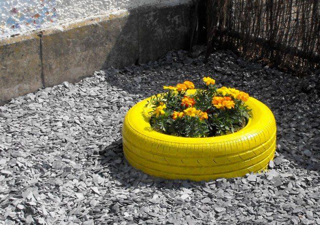 How about hanging your planter? If you have a sturdy tree or railing this could be a good place to hang it. Of course, you can also drill hooks into a wall. For a rustic look, you can use a rope tied to your tire. However, for something more secure, a chain is ideal.
The same initial steps to make a basic tire planter must first be followed. Find a tire, clean it, and choose if you want to paint it. Depending on where and how you want to hang your planter, choose the tire size accordingly. This is a good place to use smaller motorcycle or ATV tires.
When your tire has been cleaned and painted, drill some holes in the bottom half so that rainwater does not accumulate. You can put a layer of porous material such as cloth so that the soil does not fall out.
Next, drill a hole in the center at the top of the tire to insert an eye bolt, securing it with a nut on the inside. If you plan to use a rope and a solid knot, you can skip this step. From the eye bolt, attach your chain which can hang from a hook or railing as desired.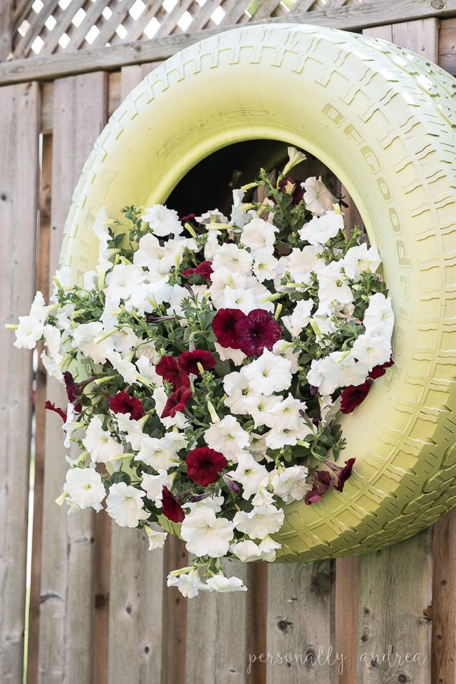
Once your tire is hanging in place, fill the bottom with topsoil. Then, plant your flowers and your hanging tire planter is ready!
Also, see this guide for making a hanging planter.
Rubber tires are made up of a large number of components, many of which are indeed toxic. This is why it is difficult and expensive to dispose of old tires. Therefore, using tires for DIY projects has lots of benefits since they do not need to be brought to a dump where they will be burned, leaching toxins into the air.
Both sides of the debate have many arguments and are ultimately inconclusive. While you can surely find many people who would refuse to use tires to grow edibles, there is no straight evidence that they are harmful. Accordingly, it really is a personal decision and risk assessment.
Tires do eventually begin to leach certain components into the soil. However, these chemicals would end up in the air if the tires were to be burned during disposal.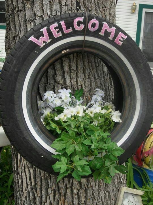 Generally, it is understood that it would take decades for the tire to really begin to degrade. At that point, it is also not certain whether the molecules released would actually make it into the plant.
A good compromise if you plan to use your planter for edibles is to rotate them for flowers after a few years. However, if you want to be as safe as possible, simply avoid using tire planters for food plants and stick to decoration!
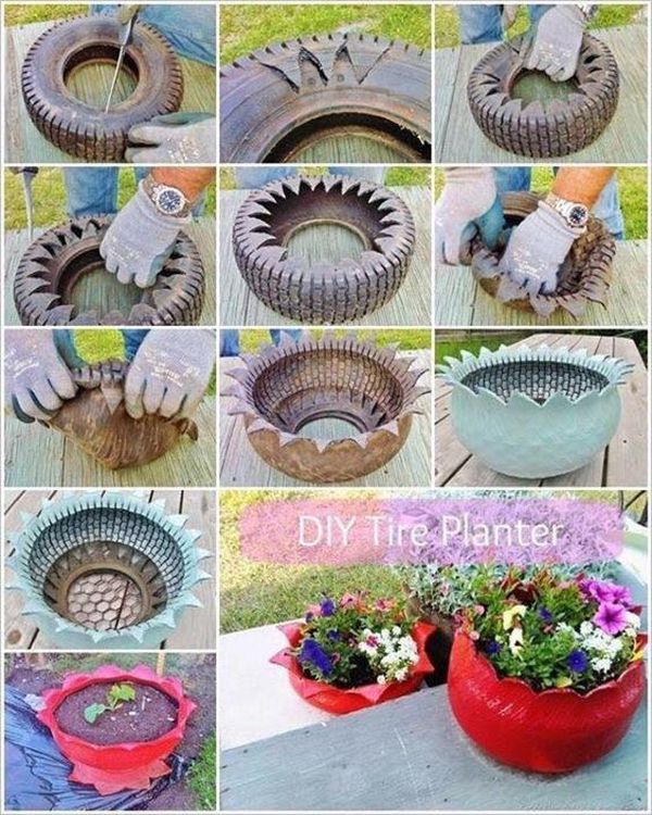
If you want your tire to look a little less like a tire, inside out planters are a unique twist on the standard. Just as the name says, these are made from tires that have been inverted. When choosing a tire to invert, there are a few extra details to consider.
Not all tires can be used to build an inside out tire planter. Older tires will be more flexible and are better suited for this DIY project. Tires can be tested by pushing the curve where the tread meets the rubber sidewall.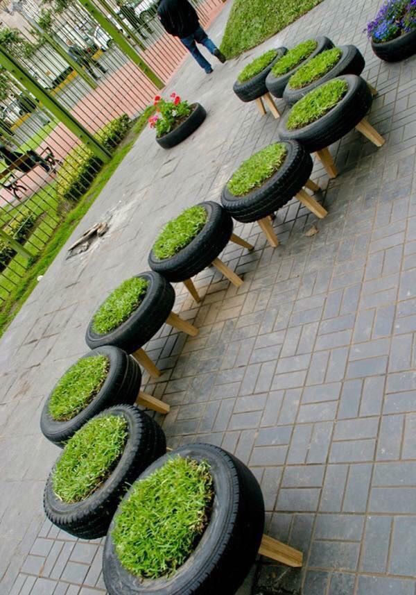 If it pushes in easily your tire will be less challenging to flip. If not, keep on looking!
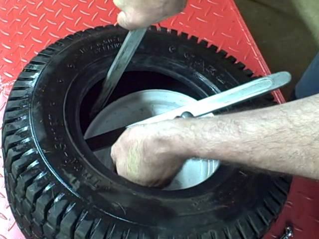
Inverted tire planters require the additional step of cutting the tire. To facilitate the process, draw a line where you want to cut. Since you are just cutting the softer inner wall, any sharp knife will do. Make sure to keep safety in mind – gardening gloves are a good idea at this stage.
Once you have cut through the tire, it is time to invert it. Find the soft spot where the curve meets the tread from the first step and push. At the same time, pull the inside cut wall towards you. It might take a few tries but once the tire starts inverting it is just a matter of making it around the circle.
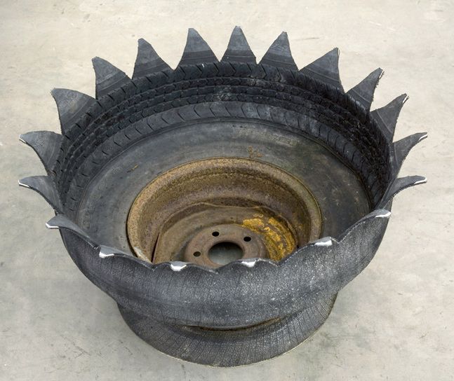
All of these steps can be done if your tire has a rim. You will simply have a pedestal for your planter! Given the force and handling required to invert your tire, wait until this step is complete before properly cleaning and painting it.
Visit felderrushing.net to see detailed photos of each step to make sure everything goes smoothly!
Not only can you use tires to make decorative planters for flowers, but you can also use them to set up a vegetable garden.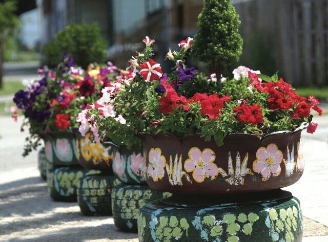 As mentioned above, since the tires are not being burned, the likelihood of toxic elements entering your vegetables is very low and would take decades. Rotating tires for different uses as well as lining them can be good ways to eliminate any risk.
There are quite a few benefits to using tires for your vegetable garden, as well as some considerations to keep in mind for maximum results.
Building raised vegetable gardens from lumber can be quite expensive so recycling tires is a great way to save some cash. As well, by raising the planters, you will avoid some ground pests and reduce weeds. Raised tire planters are especially useful for gardeners with back issues or decreased mobility as they don’t require constant bending or kneeling.
Tire planters can be a huge advantage if you live in a place with hard-packed soil. Plants can have difficulty extending their roots into these soils, whereas you can fill your planter with topsoil and compost and raise it to the height you desire by adding extra tires.
If you are painting your planter, it is important to use lighter colors if you want to plant vegetables that require cooler soil. Black tires will absorb the sunlight and heat the soil, which is a benefit for crops such as potatoes, peppers, and carrots but can easily ruin others. Since the soil will remain warmer than ground soil, tire planters are a great way to start planting earlier in the season. Common gardener frustrations such as frost won’t be an issue as your soil will stay protected.
Besides using your tires for DIY planters, a stack of tires can make a great compost bin. Stack tires until you reach the height you want. Once your bin is full, remove each tire one by one while you use the compost and begin stacking your next bin.
Paint your planter light blue to hold more delicate crops such as lettuce.
Separate your vegetables and herbs to make watering and picking extra simple.
Layer your DIY tire planters to create a tiered look.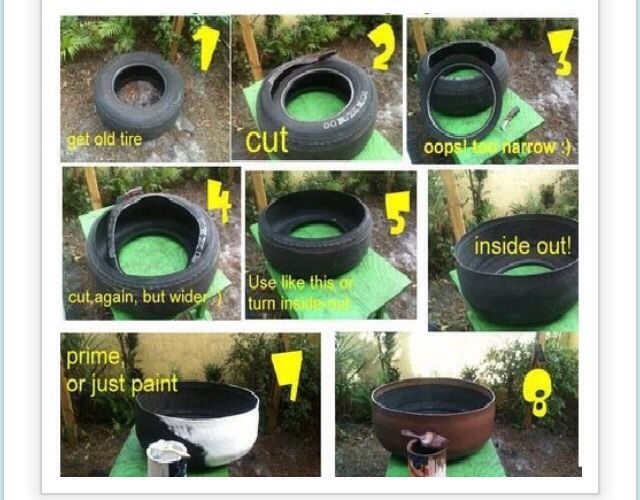 Use bright colors to complement your flowers.
Tread marks can add an extra pattern to your painted tires.
Tiered tire planters can also create low wall partitions between separate parts of your garden.
If you have plenty of tires, create this fun pyramid shape. Make sure to leave space for your flowers to grow and receive sunlight.
Think about using different sizes of tires to create a quirky look.
If you want to keep your planters low to the ground, lay them side by side with different flowers showcased in each.
A single tire planter can brighten up any corner of your garden if you fill it with colorful flowers.
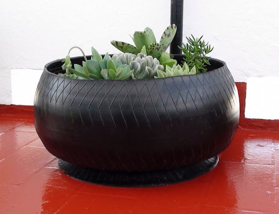
No need to stop at flowers – succulents are a great choice for filling your DIY planter.
Large tractor tires make the perfect base for small bushes.
Smaller tractor tires are great to use as individual flower pots.
If you have a large tractor tire, fill it with plants and make a flag stand.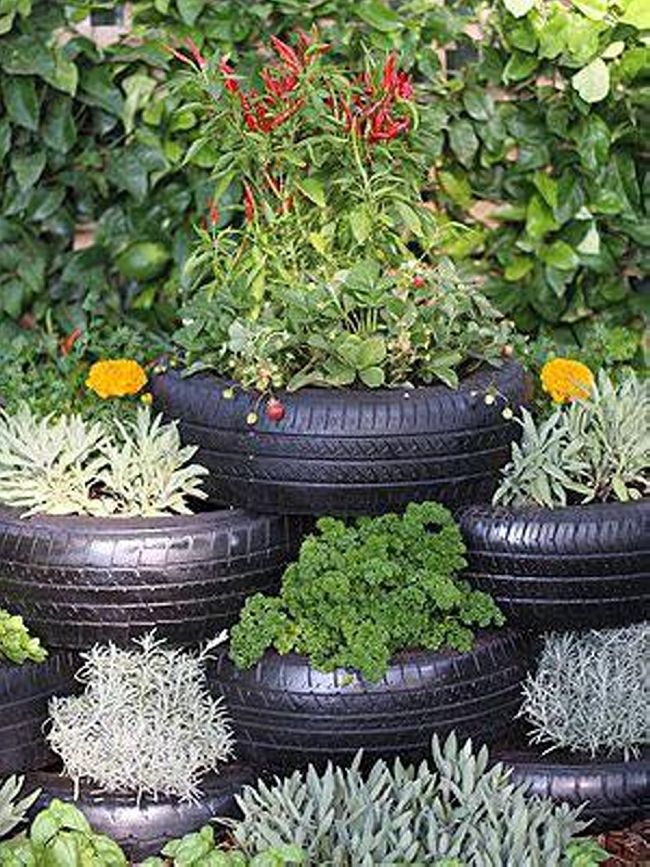
Place inverted tire planters on top of regular tires to create a cool look.
A simple inverted planter painted in a solid color looks like a star-shaped pot.
Get creative by painting your planter in different colors for a petaled look.
Inverted tire planters can also be stacked to create layers.
No need to worry if your tire still has a rim. Your inside out planter now has a pedestal!
Stacking tires for your DIY planter is a great way to make all your plants visible.
A single stack of tires can make a great focal point for your entrance.
If you have lots of tires, why not create a wall?
Stacked tire planters near your balcony make it easy to water your plants from above.
If you’ve always wanted your very own wishing well, look no further! A few stacked tires with the right paint job will do the trick.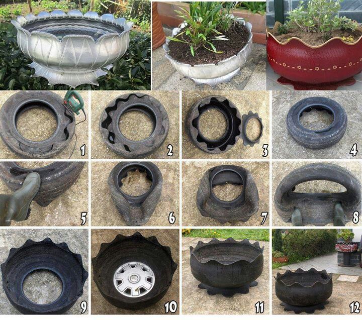
Patterns and designs are a great way to add life to your recycled tires.
Anywhere you can attach a hook makes a good home for a hanging planter.
Decorate stone walls with brightly painted hanging tire planters.
Bring a brick wall to life by painting it in pastel tones and hanging planters.
As long as your plants are happy, you can fill your new DIY planter to the brim!
No need to go overboard with different flowers. A simple plant will look great.
Make sure to have some fun while doing your DIY project!
Feel free to leave your tire paint free and natural, the bright flowers are sure to compensate.
A solo tractor tire is a great piece to display some blooms.
Bamboo walls make a great spot to hang your tires. Fill them with flowers and greenery to brighten up your space.
Simple stacked tires make a great home for creeping plants.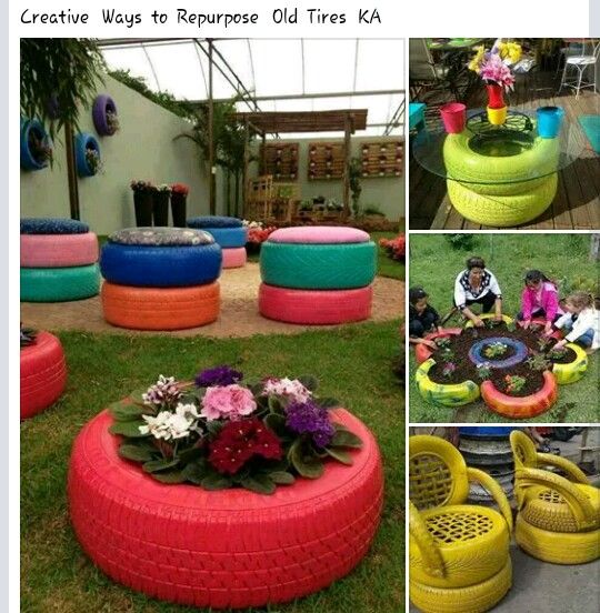
If you are motivated, the options are truly endless. Tires decorated as sushi rolls, animals, teacups, and wishing wells are just some of the multitude of DIY projects you can do with recycled tires.
Depending on the style of teacup you want to make, you can use an inverted tire with a rim, or stack two tires to make your base. You can get creative with the handle; for example using strips cut from a tire, plastic, an old garden hose, or a hardened rope. Simply screw the two sides at the level you prefer.
Check out these two videos for different takes on teacup designs.
A very detailed approach using stacked tires.
A simpler teacup using an inverted tire with a rim.
If you want to create a design that resembles a pot instead of a flat tire, be sure to use a tire with the rim still on. Then, follow the same steps as for your inverted planter with the rim acting as your stand.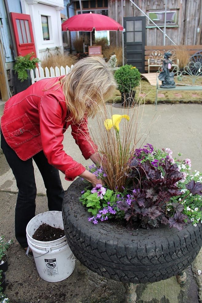
Bring the tropics to your garden with these DIY hanging parrot and toucan tire planters.
Who knew what a knife, some green paint, googly eyes, and determination could accomplish?
Make sure you have a sharp knife and draw your cutout lines when attempting these floral designs.
Stone walls can be the perfect backdrop for your tire wall. Secure everything in place to avoid any mishaps.
Did someone say swan lake?
Cut your tires in half to make this flower-shaped bed.
It’s tea time!
But what to do if the erased tire relief does not give the proper level of grip? In this case, you need to take a groover to cut the tread and restore the grip level. How to do it? Read about it in our article.
Factory cutting of lamellas in car tires involves the creation of grooves with a sufficient depth, but over time their height melts, rubbing against the asphalt and the ground surface.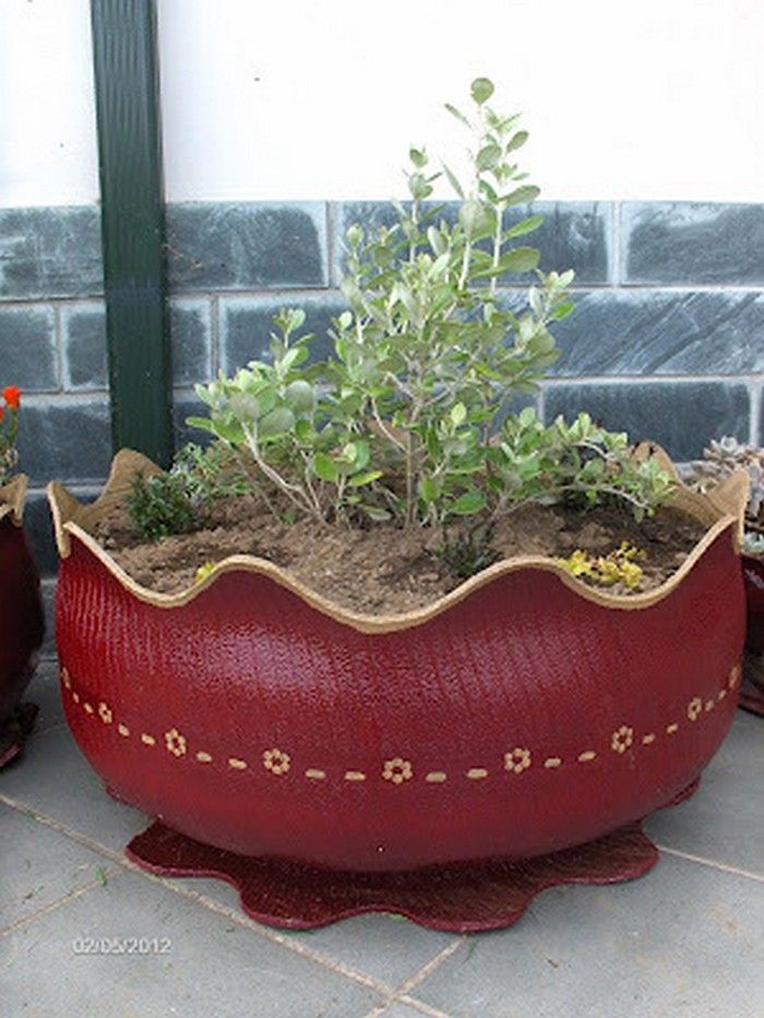
The minimum admissible knurling depth cannot be less than:
If the tire is worn down to the marker sewn into the rubber, you will have to buy a new tire. If you want to avoid unnecessary expenses, try cutting new grooves in thick rubber before its height drops below 0.8-2.0 millimeters.
To restore rubber, you will need a special groover knife and a good eye. If you have the skills and a special tool, you can cut the tread with your own hands in just one or two hours, saving a lot of money. However, this technology does not work with all tires.
| Photo of UAZ car tire before cutting | Photo of UAZ tire after cutting |
|
| |
The widespread fascination with ecology and the threat of global warming has changed the fate of worn wheels. Previously, such tires formed man-made mountains in every landfill. Today, according to the requirements common in the European Union, the following types of tires are subject to mandatory restoration:
Restoration of truck tires and swamp tires for SUVs is possible only with the assistance of a manufacturer who has provided for compatibility with cutting technology at the rubber production stage. Therefore, it is possible to cut tires at home only if the inscription - REGROOVABLE is read on their sides.
If you do not see such an inscription, contact a car repair shop or abandon the idea of \u200b\u200bretreading. After all, the wheel of a passenger car is pumped up to 2.5 atmospheres, and up to 8 bar is blown into the tire of a truck, so even the slightest mistake when cutting will reduce the life of the tire several times.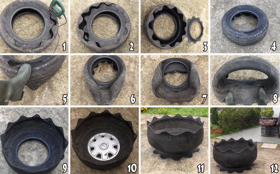
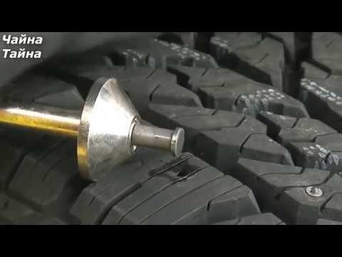
Before cutting new grooves on the tread, you need to find a device suitable for the case. In auto repair shops, a special machine for car tires is used for these purposes, and home craftsmen prefer to cut the tire with their hands using knives or machines.
The most popular tread cutter is the electric regrower. This knife-soldering iron hybrid cuts grooves from 0.5 to 5 millimeters deep to create a new tread pattern. Even a cast tire cannot resist such a cutter. Moreover, the combined (thermal and mechanical) effect on the rubber does not involve great effort when cutting. A professional device for restoring lamellas differs from a tool for garage craftsmen in the ability to change cutting nozzles. Manufacturers of such machines produce special sets of nozzles for each brand of car or truck tires. Some tools allow you to cut several lamellas at once in one movement.
Reducing the tread depth reduces the tire's grip on the road, so to improve stability, you need to deepen the existing grooves without widening them.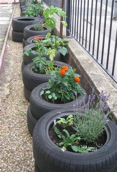 For these purposes, you need to find a special regrower attachment or make a homemade knife for passenger tires and cargo treads.
If tires are cut with a car regrower, the tool moves from the center of the tread to its edge. In this case, you need to control the position of the elbow - it must remain in a plane parallel to the contact patch. If you raise or lower your elbow during a cut, an extra hole or an area that is not selected in depth will appear on the tread.
When cutting thick truck tires or cast tires for special vehicles, this error can be corrected by transferring them to a car repair shop. Thin passenger tires do not forgive such failures. You can ruin a tire in just one awkward move. Therefore, most often, owners of old tires for UAZ, ZIL or GAZ take up self-cutting, but it is better for owners of passenger cars to restore their tires only in the workshop.
Summer Drive Protection Sound Comfort
Rating:
4. 5
5
Tires Goodyear Eagle F1 Asymmetric 3 SUV
Summer Drive protection
Rating:
4.5
Tires Goodyear Eagle Sport TZ
Summer Drive protection
Rating:
4.5
Tires Goodyear EfficientGrip 2 SUV
Summer Drive Protection Run On Flat
Rating:
4.5
Tires Goodyear EfficientGrip Performance
Winter Drive protection
Tires Goodyear UltraGrip Arctic 2 SUV
Winter Drive Protection Sound Comfort
Rating:
4. 5
5
Tires Goodyear UltraGrip Ice 2
Winter Drive Protection Sound Comfort
Rating:
4.5
Tires Goodyear UltraGrip Ice SUV
Winter Drive protection
Tires Goodyear UltraGrip Performance+ SUV
All season Drive Protection
Rating:
5
Tires Goodyear Vector 4Seasons Gen-3 SUV
Summer Drive Protection Run On Flat
Rating:
4
Tires Goodyear Wrangler HP All Weather
All season Drive Protection
Rating:
4. 5
5
Tires Goodyear Vector 4Seasons
Summer
Rating:
4.5
Tires Goodyear Wrangler All-Terrain Adventure with Kevlar
Summer Drive Protection
Rating:
4.5
Tires Goodyear EfficientGrip SUV
Summer Drive Protection Run On Flat
Rating:
4
Tires Goodyear Eagle F1 Asymmetric SUV
 After that, carry out the entire complex for cleaning the wheels before selling - remove the dust, wash the rubber from the inside and out, perform blackening. It is much more pleasant to work with a clean tire, especially if you do all the work with your own hands and home tools.
 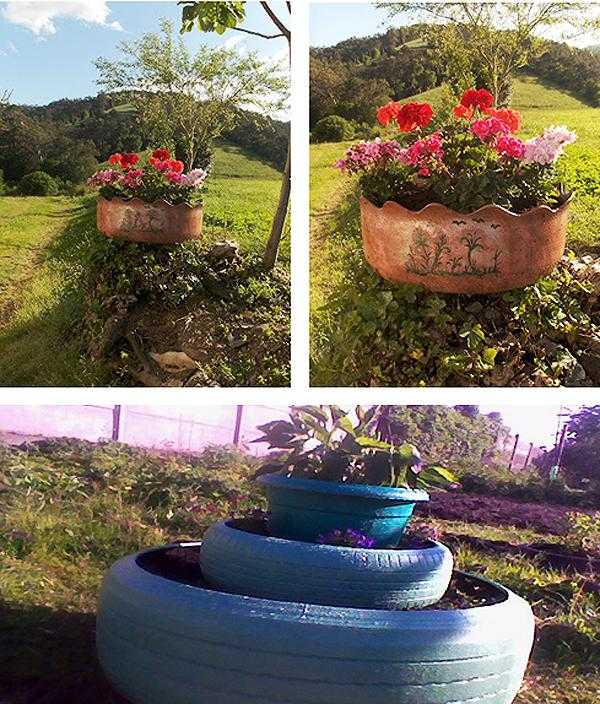 Just do not press the tool on the tire - this way you can cut the rubber through and through. A professional does the job in several passes.
This video shows the sequence of processing a tire by a professional groover. As you can see, the master uses special nozzles that allow you to neglect measuring the depth of cut.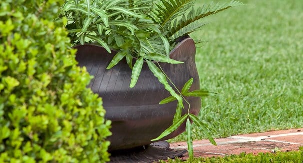 This saves time and improves the quality of processing.
If you want to go that route, first check how much professional cutting equipment costs. It is possible that its price will seem excessive to you, and you will prefer to order this work from professionals.
This video shows how the homemade tool works. A machine made from a conventional soldering iron works no worse than professional equipment. A heavily worn tire is covered with new grooves in just 6-7 minutes. But if you want to go this route, pay attention to the impossibility of adjusting the depth of cut. In fact, it depends on the pressing force. The author of the video suggests “cutting the tire as you like,” which does not guarantee the long life of the rubber and the safety of the vehicle owner.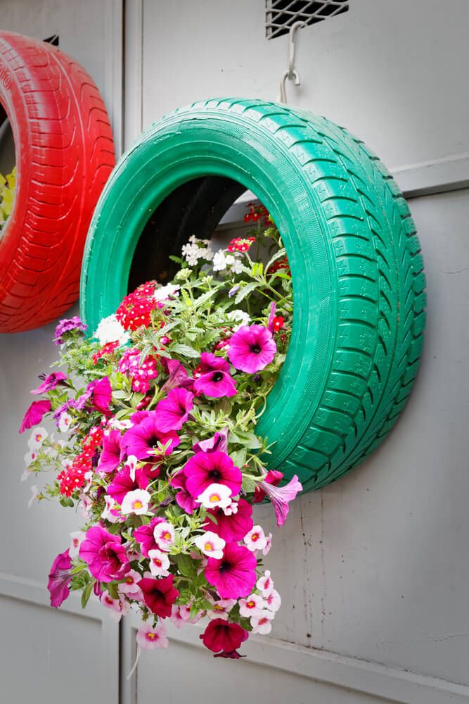 Thoughtless work can provoke a wheel break right while driving on the highway.
Mass distribution system for seed drills and machines for applying products
Illustrations
Show all
agricultural implements with a system for distributing its mass in the working process. The agricultural implement has a drawbar, a central bar for hanging working tools extending from the drawbar, and first and second wings extending outward from the central bar for hanging working tools. The implement may comprise a system of center hoppers to provide material to individual row units along the center toolbar and wings, or may have separate hoppers located on each of the row units along the toolbar. The implement uses a weight distribution system to update and control the amount of downforce applied to the outer toolbar or wings, and separate row units. The distribution system contains an intelligent control device connected to sensors and cylinders. The intelligent control device receives information from the sensors and adjusts the cylinders accordingly to provide an appropriate amount of downforce and to control the downforce based on real time, and may be a closed-loop or open-loop system. Such a constructive solution is aimed at ensuring uniform sowing of seeds. 7 w.p. f-ly, 13 ill.
Abstract
CROSS-REFERENCE TO RELATED APPLICATIONS
Pursuant to 35 USC § 119, this application claims priority over provisional application serial number 61/665357 filed June 28, 2012, which is incorporated herein in its entirety.
FIELD OF TECHNOLOGY TO WHICH THE INVENTION RELATES
In general, the proposed invention relates to the field of agricultural equipment. More specifically, but not exclusively, the invention relates to a system for distributing the mass of an implement, such as a planter, during use of the implement.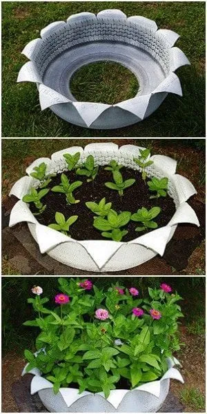
BACKGROUND OF THE INVENTION
As tractor power and agricultural efficiency increased, the span or width of agricultural implements, such as planters, increased to accommodate larger numbers of individual row units. Planters typically comprise a main frame having a front hitch for tractor towing and left and right wing sections hinged to a portion of the main frame. Pivoting wing joints allow the wings to fold over the main frame for planter transport and storage.
Traditional row crop planters use separate seed hoppers attached to each individual row unit to sow the seed. They require bagged seeds to be filled manually, either with an auger, or by gravity flow from seed containers supplied by the seed company. The process is labor intensive and time consuming, so systems have been developed whereby large centrally located seed bins can be filled in large batches by gravity using auger or box seed tender system, saving time and reducing labor costs.
However, the addition of centrally located seed hoppers creates additional problems.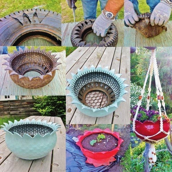 Hoppers add significant mass (over 5,000 pounds) to the center transport axles by moving the pre-distributed mass to the center of the planter. The extra weight significantly increases the contact pressure of the main transport tires on the soil, causing compaction which can result in reduced yield per unit area.
Mass redistribution also removes approximately 200 pounds of potential mass from each individual row unit. The row units of the planter require downforce to facilitate and maintain the penetration of their opener blades into the soil to cut a seed furrow of constant depth in the soil for planting. With the mass of local seed hoppers now removed, the consistency of soil penetration and furrow depth in hard soil, especially in uncultivated soil, is at risk. To help counter this problem, a means of applying spring, pneumatic, or hydraulic downforce to the row units has been used. Downforce led to another problem. Downforce creates a lift in the implement bar on which the row units are mounted, reducing traction and tire contact pressure on the ground, causing friction driven tires to slip on the ground.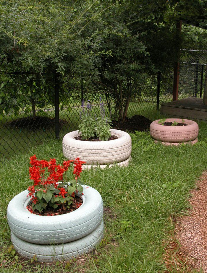 Variation can lead to planting errors or inconsistent spacing, which can adversely affect yield per unit area.
To counteract the problems mentioned above, a means of applying downforce between the central frame of the planter and the wings of the implement bar at the flexion points of the following wings was used. The clamping force effectively improved both situations, but only for the case with a given load, since the applied force is constant. Since the field may contain varying hardness and ground conditions, the amount of downforce applied in one area may not be suitable for other areas. Thus, the field will not be sown systematically, which will affect the total yield per unit area for the field.
As a result, there is a need in the art for a system that can control the amount of downforce applied to the center toolbar and wings so that planting depth is constant and soil compaction is minimized for varying ground hardness conditions. There is also a need in the art for a system that will automatically update the amount of downforce applied to wings based on real-time changes in ground hardness in the field.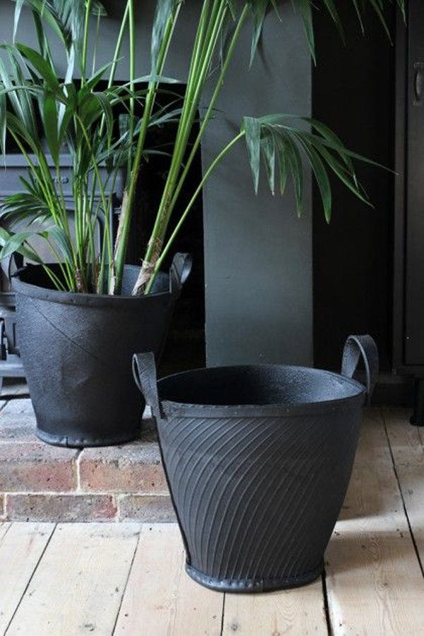
SUMMARY OF THE INVENTION
Therefore, the main object, feature and/or advantage of the proposed invention is to overcome the disadvantages in this field.
Yet another object, feature, and/or advantage of the present invention is to provide a system that will detect the hardness of the ground in order to determine the correct amount of downforce to be applied to the planter's wings.
Yet another object, feature and/or advantage of the present invention is to provide a system that will automatically adjust the amount of downforce applied to the wings based on the hardness of the ground, the weight of the hopper and/or other factors.
Yet another object, feature, and/or advantage of the present invention is to provide an open-loop control system that allows the operator to adjust the amount of downforce applied to the wings based on information received from sensors on the implement bar, wings, and sowing sections.
Another additional object, feature and/or advantage of the proposed invention is to provide a feedback control system that varies the applied downforce in order to distribute the mass between the center section and the outer wing sections of an agricultural implement, based on a constantly changing measured or calculated proportion in total mass on any or all engaging road wheels to distribute load and minimize ground compaction.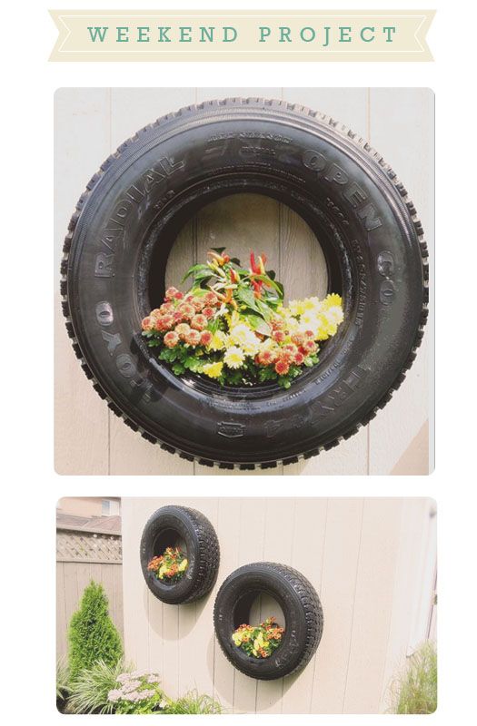
Another additional object, feature and/or advantage of the proposed invention is to provide a control system for automatically optimizing seed depth and minimizing field compaction using a sensor system to measure and balance wheel load with instant control of the hydraulic force of the planter.
These and/or other objects, features and advantages of the present invention will be apparent to those skilled in the art. The proposed invention should not be limited to these tasks, features and advantages. There is no need for a single embodiment to provide every single task, feature, or benefit.
The invention comprises a control system that varies the applied downforce to distribute mass between the center section and the outer wing sections of an agricultural implement based on a constantly changing measured or calculated proportion of the total mass on any or all of the engaging road wheels to distribute the load and minimizing ground compaction. The system uses mass sensing or leveling systems to determine the percentage of the center axle in the total mass of materials contained in the centrally located chambers and will use this along with machine mass information to calculate the appropriate amount of downforce or pressure on the outer wings and their road wheels .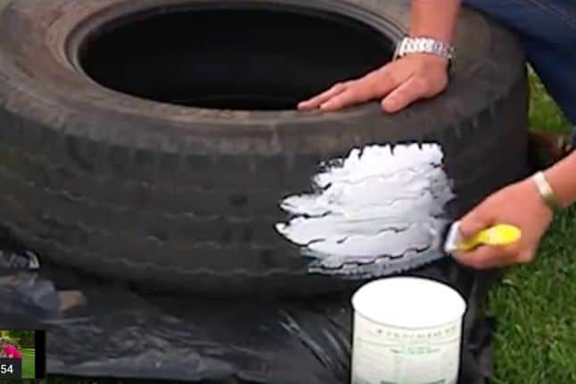 The system can be open-loop, where the downforce is changed by the operator, or closed-loop, where the system automatically updates the amount of downforce based on information from one or more implement sensors. Alternatively, any combination of many different mass and/or level systems, or mass reduction calculated from a flow sensor, can be used to also include the mass of seed materials, fertilizers and insecticides in the row unit and incorporate them into the spread mass in real time against the calculation clamping force.
According to an aspect of the invention, an agricultural implement is provided. The tool contains a drawbar having a first end containing a hitch and an opposite second end. At the second end of the drawbar there is a central beam for hanging working bodies, while the central beam for hanging working bodies contains central wheels extending from it. Right and left wings continue from opposite sides of the central bar for hanging working bodies, while each of the first and second wings contains wing wheels extending from them.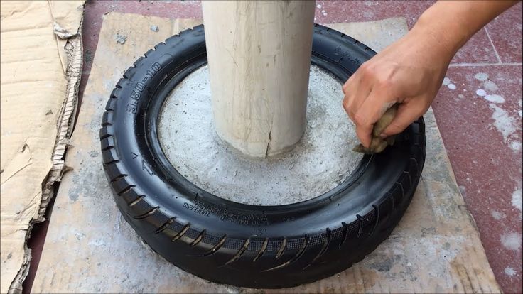 The mass distribution system is functionally connected to the central bar for hanging working bodies, the first wing and the second wing. The mass distribution system is configured to adjust the downforce on the wings to penetrate the ground and to engage the row units with the soil, either automatically or by input from the operator. The system can redistribute the mass of the implement to take into account changes in the characteristics of the implement (load, material location, etc.), as well as changes in soil characteristics (hardness, moisture, compactness, etc.).
According to another aspect of the invention, a mass distribution system is provided for an implement with multiple row units located on a central frame, a left wing and a right wing. The system comprises an intelligent control device, a plurality of sensors associated with a plurality of row units and connected to an intelligent control device, and a plurality of cylinders operatively connected to an intelligent control device and left and right wings. The intelligent control device is configured to use information from the sensors to control the plurality of cylinders such that the wings receive downforce based on information received from one or more of the plurality of sensors.
According to another aspect of the invention, a method for distributing mass around the central frame, left wing and right wing of an agricultural implement is provided. The method includes determining one or more characteristics of the implement, the ground, or both, using one or more sensors, and adjusting one or more cylinders of the implement to control downforce on the left wing, the right wing, or both, based on the characteristics determined by one or more sensors.
BRIEF DESCRIPTION OF THE DRAWINGS
The appended claims set forth these novel features which characterize the invention. However, the invention itself, as well as its additional objects and advantages, will be better understood by reference to the following detailed description of an embodiment, made in conjunction with the accompanying drawings, in which the same reference characters designate the same elements throughout the various drawings, in which:
Fig.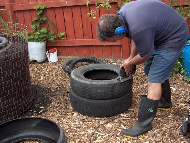 1A and 1B are perspective views of an agricultural implement for use with the systems of the present invention;
Fig. 2 is a vertical sectional view from the rear of the gun of claim 1;
Fig. 3 is a view of a row unit for use with mass distribution systems of the present invention;
Fig. 4 is a block diagram of a mass distribution system according to the present invention;
Fig. 5 is a perspective view of a portion of the implement showing sensors located adjacent to the central bunker of the implement;
Fig. 6 is a diagram of an exemplary remote depth control system for an implement having a plurality of row units;
Fig. 7 is a block diagram of a mass distribution system according to the present invention;
Fig. 8 is a schematic rear view of an embodiment of an implement having a mass distribution system according to the present invention;
Fig. 9 is an enlarged rear view or part of the gun of FIG. eight;
Fig. 10 is an enlarged rear view of one half of the gun of FIG.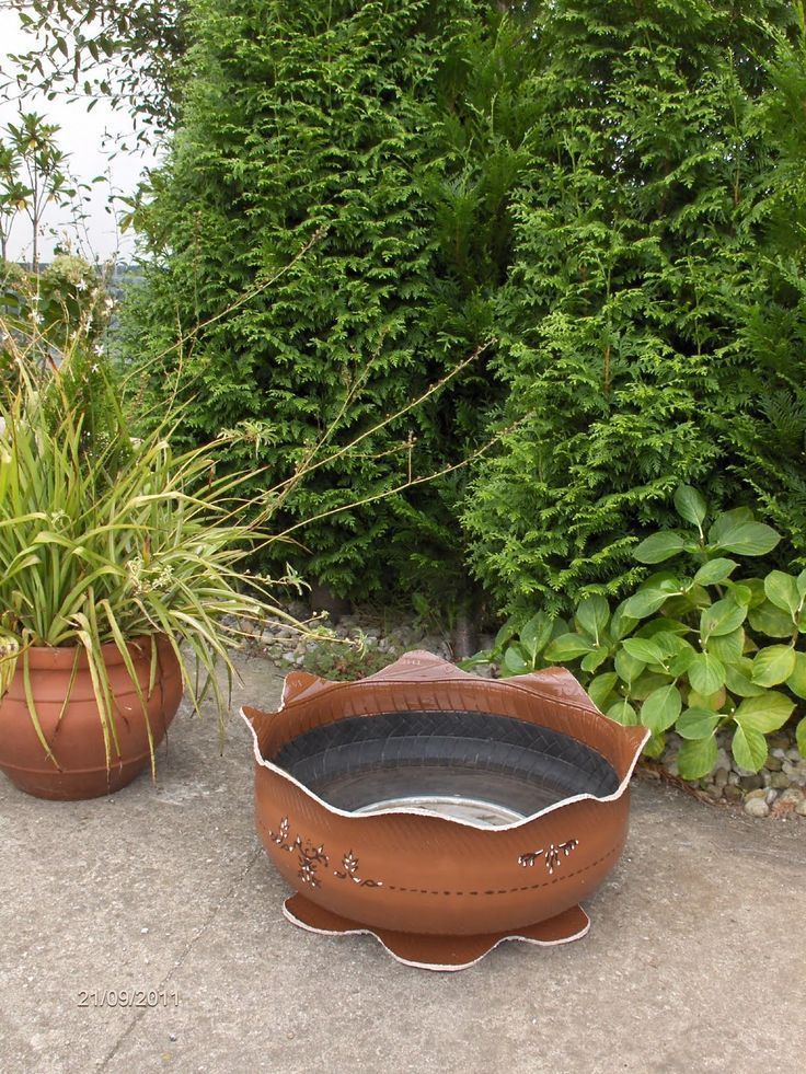 8 having a mass distribution system;
Fig. 11 is another enlarged view of part of the gun of FIG. eight; and
Fig. 12 is an enlarged perspective view of a cylinder of a mass distribution system according to the invention.
Before a detailed explanation of any independent features and embodiments of the invention, it should be understood that the application of the invention is not limited to the details of construction and configuration of the constituent parts set forth in the following description or illustrated in the drawings. The invention is capable of other embodiments and of being practiced or being carried out in various ways. In addition, it should be understood that the phraseology and terminology used herein is intended to be descriptive and should not be construed as limiting.
DETAILED DESCRIPTION OF THE PREFERRED EMBODIMENTS
Contents of U.S. Application No. 13/458012, filed April 27, 2012, U.S. Application No. 13/457815, filed April 27, 2012, and U.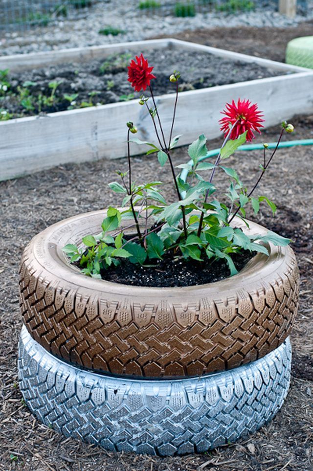 S. Application No. 13/457,455 filed April 127, April 27, 25 are incorporated herein by reference in their entirety.
Fig. 1A, 1B and 2-4 show an agricultural implement 10, in this case a planter, for use with systems according to the invention. The implement 10 may be a planter, a fertilizer machine, and the like, which is typically attached to and pulled by a tractor 12. However, it should be understood that the implement 10 may move other equipment and/or vehicles. For the purposes of the proposed disclosure, the implement 10 will be referred to as a planter. Fig. 2 shows a sectional view from the rear of gun 10.
The implement 10 includes a drawbar 14 having a first end 16 and an opposite second end (not shown). The drawbar 14 includes a hitch 18 at a first end 16, with the hitch 18 connected to a tractor 12. At the second end 20 of the drawbar 14 is a central bar 22 for attaching working bodies. The drawbar 14 may be a telescoping drawbar, the constituent parts of which can be inserted into each other so that the implement 10 is of the front folding type.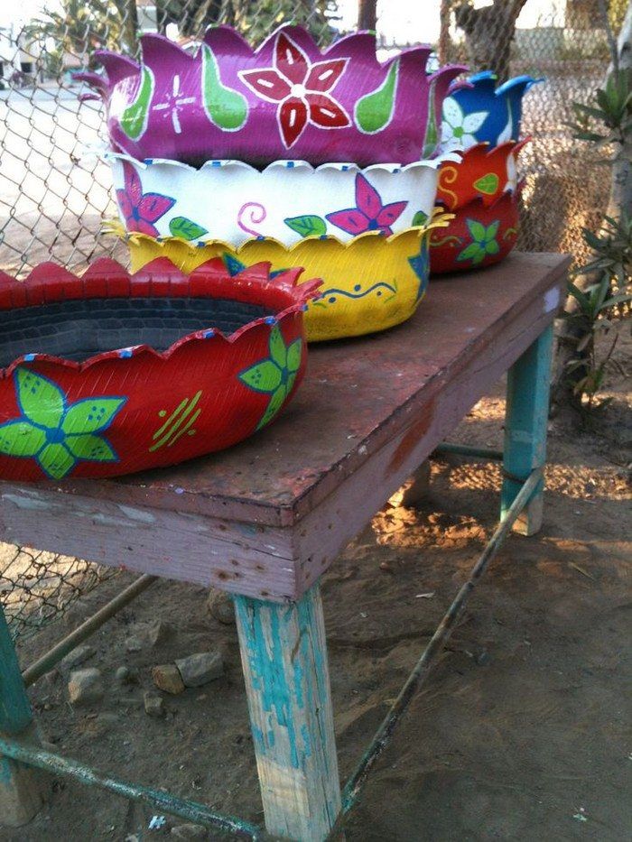 However, the present invention should not be limited to such a front folding type implement, as it should include any such implement for use in the agricultural industry.
As shown in FIG. 1A, 1B and 2, the central hoppers 24 are located on the central bar 22 for hanging the working bodies. The hoppers 24 are configured to store seeds, fertilizers, insecticides, or other types of material for agricultural use. The use of central bins 24 allows for the addition of a large amount of material in a central location. However, as will be discussed, the invention also provides for the use of multiple bins 39located in each of the metering units 34. When the center hoppers 24 are used on the center bar 22 to hang the tools, it should be understood that the center hoppers will be in pneumatic communication with each of the row units 34. Also connected to the center bar to hang the tools a plurality of central wheels 26 extending generally downward from the central beam 22 for attaching the working bodies.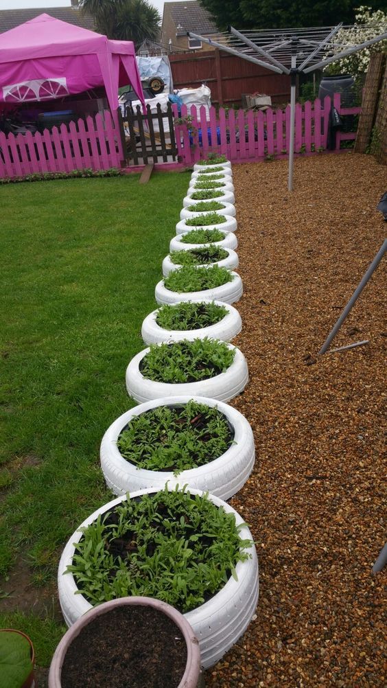 The wheels contact the ground and support substantially the entire mass of the center bins 24. The wheels stabilize the implement 10 and are generally wheels that contact the ground when in the working position or in the transport position, for example if the implement 10 is a forward folding implement, so that the wings 28, 30 are folded forward without the wheels of the wings 32 being in contact with the ground.
The first and second wings 28, 30 continue from both sides of the bar 22 for hanging the working bodies. The wings 28, 30 are generally identical and are mirror images of each other. Because of this, only one wing will be described, with the understanding that the other wing will generally have the same configuration. The first wing 28 includes a bar 29. A plurality of row units 34 are mounted on the bar 29, as well as a plurality of wheels 32. The wheels 32 are configured to contact the ground most of the time. The row units 34 may be seed drills, fertilizer spreaders, insecticide sprayers, or other spreaders, discs, or plows. The wings 28, 30 may also include at least one folding cylinder 42 and a downforce cylinder 52. Additionally, it is envisaged that a plurality of downforce cylinders should be used with an implement having more sections. The folding cylinder(s) 42 are configured to fold the wings from the position shown in FIG. 1A, 1B and 2 to a position where the first and second wings 28, 30 are generally adjacent to the drawbar 14 of the implement 10. As a result, the folding cylinders 42 must be strong enough to allow movement of the wings.
The downforce cylinders 52 provide downward force on the wings as shown by arrow 66, or the cylinders 52 may lift the wings in the opposite direction of arrow 66 to reduce ground contact pressure. The wings may need to be raised when turning or when folding the wings. However, as the wings extend generally outward from the tool attachment bar 22, the down force of the wings may be required to ensure that the row units 34 penetrate or remain substantially engaged with the ground.
Fig. 3 is a view of a metering unit 34, and more specifically, a seed meter including a seed meter 36 and a planter for use with the present invention. The sowing section 34 includes a seed meter 36, a coulter 38, row hoppers 39 and a furrow closing device 40. In order to have the best yield per unit area, it is essential that the seeds are sown at a generally uniform depth, as well as at the correct depth for the best growth of the crop or plants. Seed depth depends on many factors, such as soil moisture content, soil temperature, etc., as described in more detail in US application No. 13/458012. The present invention contemplates that, in order to determine soil characteristics, implement 10 and tractor 12 may comprise constituents of application 012. As a consequence, a plurality of row units 34 must all cut a furrow based on soil and seed characteristics, which may be approximately the same. depth for all row units. This will ensure that all seeds are in the ground at the same depth, regardless of the condition of the ground.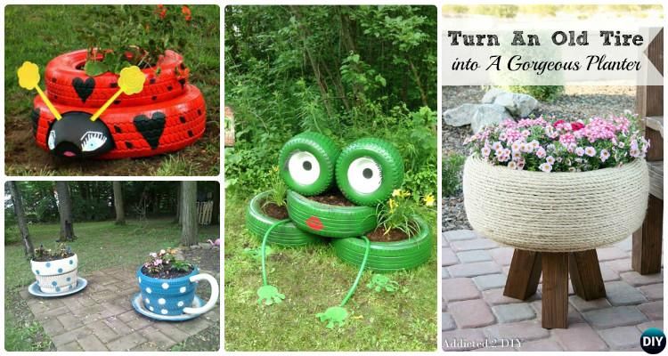 However, as ground hardness and other conditions change, it can be a challenge to get exactly the same seed depth.
As discussed above, cylinders 52 provide down force to first and second wings 28, 30. Down force is needed to press row units 34 into the ground with the appropriate amount of force to penetrate the ground to approximately the required depth. However, some factors can make this difficult. For example, when the central hopper 24 is filled with material, most of the mass of the tool 10 will be concentrated on this central bar 22 for hanging the working elements. Other additional devices, such as tanks containing liquid fertilizers or insecticides, increase the mass concentrated on the central bar for hanging the implements. A sensor, such as a pressure or load cell, may be placed at the bottom of the hoppers or accessories to measure the weight of material in the hoppers or accessories, including the weight of liquid fertilizer in the liquid fertilizer tank of the accessories.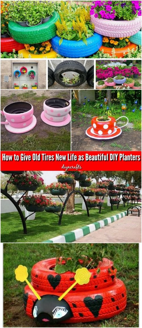 The mass and force felt on the center tool bar 22 may cause the wings to lift in an upward direction relative to the center tool bar 22. As a result, the downforce provided by the downforce cylinders 52 is adjusted to counteract the weight of the center hopper, other attachments, and/or the hardness of the ground in order to maintain an even weight distribution across all row units. Additionally, when the hardness of the ground under the wing(s) 28, 30 differs from the hardness under the center bar 22 for attaching the implements, it may be necessary to adjust to increase or decrease the downforce on the respective wing(s) to maintain a uniform seed placement depth. Also, while some implements provide the operator with the ability to adjust downforce, downforce adjustment may not be as fast as needed, not updated as often as required, or not changed at all. While the operator is typically in the tractor 12 while using the implement 10, the operator may not be aware of changing conditions in the field.
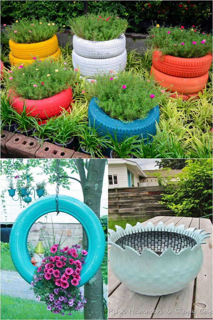
Therefore, the proposed invention comprises a mass distribution system 50 as shown in FIG. 4. The mass distribution system 50 includes an intelligent control device 56 located on or connected to the implement 10. A plurality of sensors, such as a pressure sensor 58, a flow sensor 59, a mass sensor 60, a level sensor 62, a downforce sensor 64, an accelerometer, a fluid sensor, a load sensor, and the like, are all electrically or otherwise connected to the intelligent control device 56. The sensors may be connected to the intelligent control device 56 via electrical wires, or may also be connected wirelessly. The intelligent control device 56 is also connected to the downforce cylinders 52 . The intelligent control device 56 receives data from a plurality of sensors and uses this data to adjust the downforce provided by the cylinders 52 in order to provide the optimum downforce to have the row units 34 penetrate the ground at or near the desired depth, or along at least remain substantially engaged with the ground.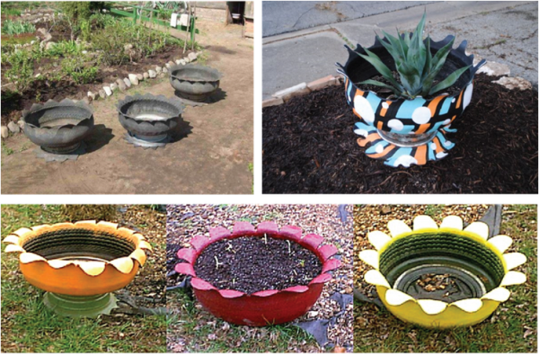
It should also be understood that the intelligent control device 56 may be located on the tractor, for example, through a control system and the like, where the operator can see the data received by the sensors and the amount of downforce provided on the wing(s). An intelligent control device may be included in the control system as shown in FIG. 4 US Application No. 13/457815, or elsewhere. The proposed invention should not be limited to the exact location of the intelligent control device, which is described in illustrative embodiments of the proposed invention. Also, when the system is an open loop system, the tractor operator can use the control system to communicate with the intelligent control device to control downforce on the wing(s).
In the illustrated exemplary embodiment, the mass distribution system is generally a feedback control system that varies the applied downforce to distribute mass between the center section or center bar 22 for attachment of the implements and the outer wings 28, 30 of the implement 10.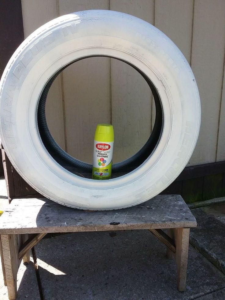 the force is changed and updated on a real-time basis, based on a constantly changing measured or calculated percentage of the total mass on any or all of the engaging road wheels 26, 32 to distribute the load and minimize ground compaction while also providing optimal depth penetration by the row units 34. Sensors 60 determine the mass levels of the central hopper(s) 24 or detect the level of the wings through the level sensor 62 of the individual row units 34 to determine the proportion of the central bar 22 for hanging working bodies in the total mass of materials, containing located in centrally located chambers, and using this information, along with information about the mass of the machine, to calculate the appropriate amount of downforce pressure on the outer wings 28, 30 and their road wheels 32. Sensors 60 can be torque elements located under the hoppers, as shown in fig. 5. As shown in FIG. 5, a torque element 60 may be located below the center bin(s) to provide an updated mass for the amount of material in the bin(s).
 It should also be noted that the torque element shown in FIG. 5 is wired to an electrical source that may be present on a tractor or implement, as discussed in US Applications Nos. 13/458,012, 13/457,815, and 13/457,577. The torque cells are one type of sensor that can be used with the present invention to determine the amount of mass in the central hopper 24. The torque cells can be in communication with the intelligent control device as well as the control system inside the tractor so that the operator can receive an updated value for the amount of material in the hopper.
Thus, the intelligent control device 56 detects the wheel pressure sensor based on the level of ground hardness, the weight of the row units and the center bar for attaching the working tools based on the amount and location of material of the tool 10, the levelness of the row units on each of the wings 28, 30, and also the amount of downforce currently provided by cylinder 52 to determine the optimum amount of downforce and automatically adjust that downforce on a real-time basis as ground conditions and mass conditions change for implement 10.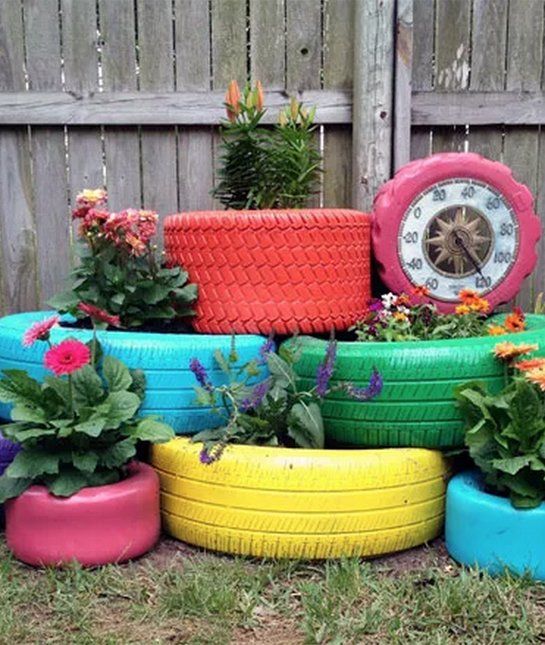 The operator will not have to adjust any aspect of your tractor 12 or implement 10, as the system 50 will automatically detect and adjust the cylinders accordingly.
As a result, the wheels 26, 32 may include torque elements on the wheels, the torque elements determining the mass acting on the wheels, as well as the amount of force applied to the wheels by the ground. The system can be configured to have a predetermined amount of force for ideal seeding conditions and the torque elements will be able to detect any deviation from this amount of force. The system will be able to adjust the amount of downforce based on a deviation from the ideal or preset amount of force, which may mean row units are not penetrating to the desired depth.
In yet another exemplary embodiment, mass distribution is generally an open-loop control system that varies applied downforce to distribute mass between the center tool attachment bar 22 and the outer wings 28, 30. In an open-loop system, the mass distribution system uses one or more sensors to measure one or more parameters of the central hoppers 24, the row units 34, the outer wheels 32, and so on.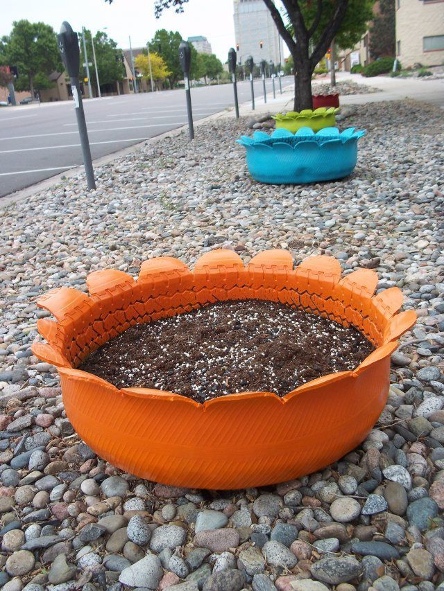 The processing unit or intelligent control device receives the measured parameter(s) and displays or otherwise outputs the information to the user via a user interface, and the user is able to make the necessary adjustments to the mass distribution system using input devices such as, for example, a touch screen user interface or a mechanical control Panel.
An example of a control system for an open-loop system is shown in FIG. 6 which shows the user interface, processing unit and memory. The control system will display output from multiple sensors at locations on the implement, and the operator can selectively adjust downforce for the wing(s) via a user interface. The adjustment may be based on historical data about conditions, mass characteristics, output from sensors, etc., or based on suggested input from an intelligent control device. For example, the control system may contain warnings or other indicators to let the operator know about changing conditions, based on which the operator can adjust the system parameters to account for changing conditions, for example, the operator can increase the downforce based on the warning that the ground compaction has changed.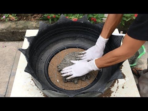
The illustrated illustrative seeding depth control system 128 includes a tractor 12 and an agricultural device 10, such as, for example, a planter, connected and towed by the tractor 12. Tractor 12 includes a control system 236 and an electrical power source 240 to drive the control system 236. The control system 236 includes a user interface 244, a processing unit 248, and a memory 252. In some illustrative embodiments, the user interface 244 may have touch screen capabilities 256, thereby providing the user with an output display for viewing information and a method for entering information through a keyboard, touch buttons screen or other touch screen controls and capabilities. In other illustrative embodiments, the user interface 244 may be only an output device for displaying information, and the control system 236 may include a mechanical control panel 260 containing a plurality of mechanical switches, keys, and so on. to manipulate the user to enter the required information.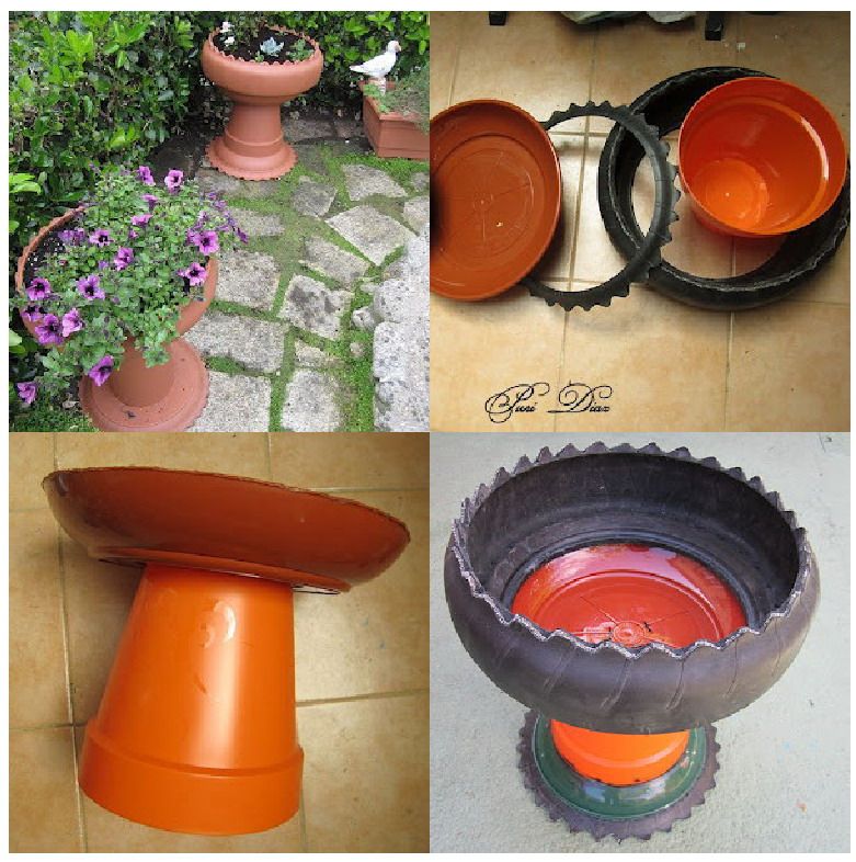 In additional exemplary embodiments, control system 236 may include a combination of a touch screen user interface and a mechanical control panel for input and output of required information. The processing unit 248 performs the necessary processing to achieve the desired operation of the seeding depth control system 128 and interacts with input devices, output devices, memory, and, if necessary, with the agricultural device to achieve such desired operation.
Continuing with reference to FIG. 6, the agricultural device may be a planter 10, wherein the planter 10 may comprise a plurality of planter row units 34. Seeder 10 may contain any number of row units 34, an example of which are annotations: Row Unit #1; Seeding section #2; Row unit #N. As indicated above, the row units 34 may be substantially the same and, therefore, only the details of the row unit #1 are shown in detail. It should be understood that all row units 34 may contain similar parts and functionality to those of row unit #1, but for the sake of brevity, such parts and functionality will not be suggested in this specification.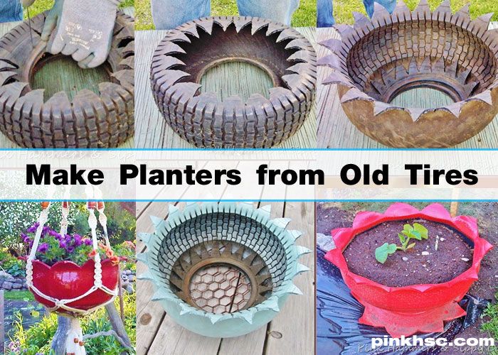 Alternatively, the mass distribution system 50 may use any combination of a variety of different levels and/or mass detection systems, or weight reduction based on the calculated flow sensor to include the mass of materials, seeds, fertilizers, and insecticides in the row units, and include them in the first calculation. downforce in real time based on distributed mass. This alternative method can be used when row units contain single hoppers rather than being supplied all from central hoppers 24.
In addition, it should be understood that the sensors are located in each of the row units 34 or groups of row units so that the intelligent control device 56 will receive information from each of the row units 34 or groups of row units in order to properly adjust the amount downforce pressure by cylinders 52. The intelligent control device 56 will calculate information from each of the sensors on each of the metering units 34 or groups of rowing units in order to determine the appropriate amount of downforce.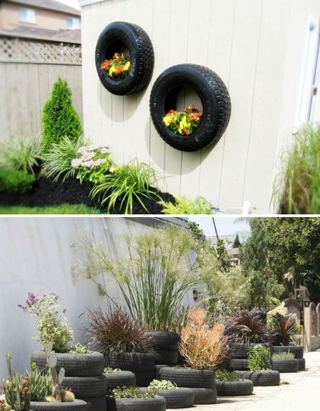 Thus, as the implement 10 moves through the field, it does not matter if the field contains both hard and soft ground conditions. The mass distribution system 50 of the present invention will take into account any and all changes in field conditions, including, but not limited to, ground hardness levels, changes in field flatness, changes in field slope, changes in soil conditions, and so on.
Fig. 7 is a flowchart showing one process of an illustrative example of a mass distribution system 50 of the present invention. The first step 70 of the system 50 ensures that the system turns on. An operator in tractor 12 or other vehicle can selectively turn the distribution system on and off. It is important that the system is not turned on while transporting the implement from one field to another, from storage to field, from field to storage, and the like. The system should only be enabled when the implement is being used for its intended purpose. However, it should be understood that the proposed invention also includes an additional sensor so that the system 50 automatically determines when to turn on, for example, when an operator has activated the implement 10 or started dispensing material from the implement 10.
Next, the step shown at 72 includes determining the information provided by the sensors. Fig. 4 shows that these sensors may include pressure sensor 58, mass sensor 60, level sensor 62, downforce sensor 64, flow sensor 59, earth hardness sensor, compaction sensor, and the like. The proposed invention provides that not all mentioned sensors are to be used with the invention, and also that any other sensors not mentioned may be included as part of the invention.
After the intelligent control device 56 has received information from a plurality of sensors in a plurality of row units 34, the step shown in block 74 inquires whether the mass of the system is distributed between the row units 34 and/or implement 10 at the desired rate. Methods and systems for determining the depth of furrows, seeds, and row units can be found in US applications Nos. 13/458012, 13/457815 and 13/457577, all of which are hereby incorporated in their entirety. As a result, the system may include sensors, such as optical sensors, ultrasonic sensors, and the like, which can determine the depth of furrows and seeds.