Select Model
Chart is for a gallon of water weighting approx 8lbs per gallon. Water is not a typical tire fill. Methonal Alchol is a more common fill and weights 6.5lbs per gallon. Other fills like Calcium, Beat Juice, etc can be varying weights.
| TIRE SIZE | GALLONS OF WATER | ADDED WEIGHT (lbs.) PER TIRE |
|---|---|---|
| 4.00-12 | 2 | 17 |
| 4.00-15 | 2.5 | 21 |
| 4.00-19 | 3 | 25 |
| 5.00-15 | 3.5 | 29 |
| 5.50-16 | 5 | 42 |
| 6.00-12 | 4.5 | 37 |
| 6.00-14 | 5 | 41 |
| 6.00-16 | 6 | 50 |
| 6.50-16 | 7 | 58 |
| 7.50-10 | 6 | 50 |
| 7. | 8 | 66 |
| 7.50-16 | 9 | 75 |
| 7.50-18 | 10 | 83 |
| 7.50-20 | 11 | 92 |
| 9.00-10 | 9 | 75 |
| 9.5L-15 | 11 | 92 |
| 9.50-20 | 18 | 150 |
| 9.50-24 | 20 | 167 |
| 10.00-16 | 17 | 142 |
| 11.00-12 | 18 | 150 |
| 11L-15 | 13 | 108 |
| 11.00-16 | 23 | 192 |
| 11L-16 | 15 | 123 |
| 14L-16.1 | 27 | 225 |
| 16.5L-16.1 | 42 | 346 |
| 7.2-24 | 9 | 75 |
| 7.50-16 | 9 | 75 |
| 8.3-24 | 13 | 108 |
| 9.5-16 | 12 | 100 |
| 9.5-24 | 17 | 142 |
9. 5-36 5-36 | 25 | 209 |
| 9.5-42 | 29 | 242 |
| 10-16.5 | 12 | 97 |
| 11.2-24 | 24 | 200 |
| 11.2-28 | 27 | 225 |
| 11.2-34 | 33 | 275 |
| 11.2-36 | 35 | 292 |
| 11.2-38 | 36 | 300 |
| 12.4-16 | 21 | 175 |
| 12.4-24 | 30 | 250 |
| 12.4-28 | 35 | 292 |
| 12.4-36 | 44 | 367 |
| 12.4-38 | 46 | 384 |
| 12.4-42 | 51 | 425 |
| 13.6-24 | 38 | 317 |
| 13.6-26 | 40 | 334 |
| 13.6-28 | 43 | 359 |
| 13.6-38 | 57 | 475 |
| 14.9-24 | 47 | 392 |
| 14.9-26 | 48 | 400 |
14. 9-28 9-28 | 53 | 442 |
| 14.9-30 | 57 | 475 |
| 14.9-36 | 64 | 534 |
| 14.9-38 | 67 | 559 |
| 15.5-38 | 66 | 550 |
| 16.9-24 | 61 | 509 |
| 16.9-26 | 65 | 542 |
| 16.9-28 | 69 | 575 |
| 16.9-30 | 73 | 609 |
| 16.9-34 | 82 | 684 |
| 16.9-38 | 90 | 751 |
| 17.5L-24 | 55 | 459 |
| 18.4-16.1 | 49 | 409 |
| 18.4-24 | 75 | 626 |
| 18.4-26 | 79 | 659 |
| 18.4-28 | 84 | 701 |
| 18.4-30 | 89 | 742 |
| 18.4-34 | 100 | 834 |
| 18.4-38 | 110 | 917 |
| 19.5L-24 | 73 | 609 |
20. 8-34
8-34 | 128 | 1068 |
| 20.8-38 | 140 | 1168 |
Messick's offers a full line of implements so y...
6We offer field and orchard sprayers from New Ho...
70Most compact tractor buyers are new to the equi...
14We feel strongly that Messick's and our vendors...
25Messick's is the first stop for experienced own...
65Helping you understand basic terminolgy, and th...
21Videos of our customers operating their equipme. ..
..
Messick's offers a complete range of round bale...
39The right landscape equipment can turn a chore ...
8Our precision farming experts can help you sque...
5Knowing what to look for on a used piece of equ...
18We offer a line of heavy duty tractors for heav...
6If your just getting the mail, or hauling a hea...
Search the catalogs for specific equipment.
OR
[Find by Model]
Currently searching parts for:
None
Choose from your equipment:
None
View My Equipment | Search Without Model
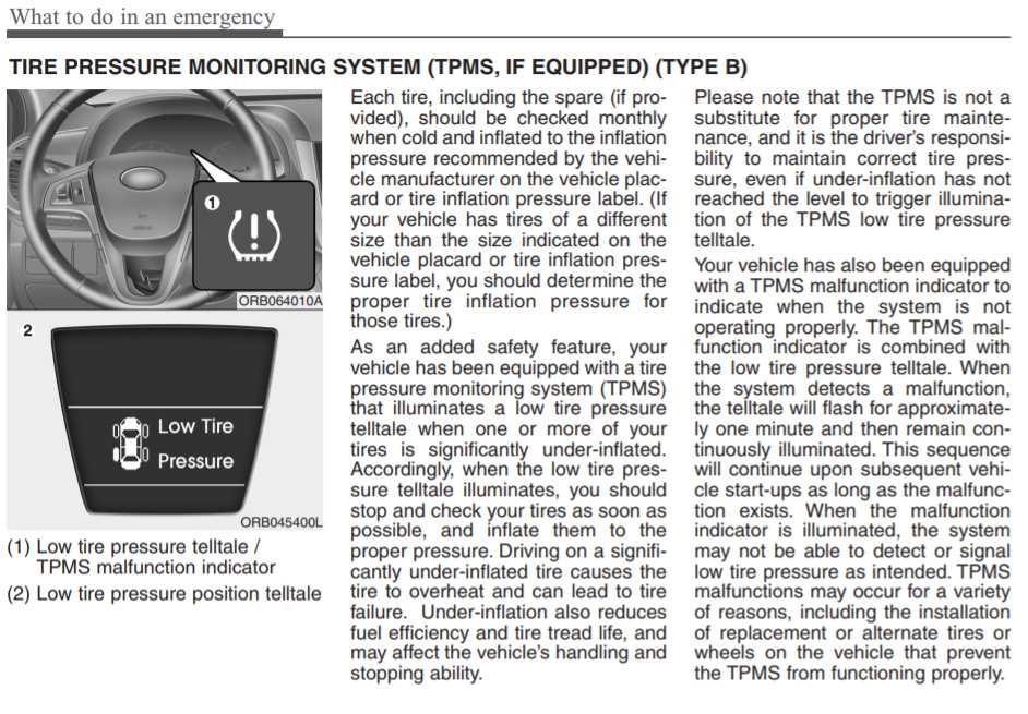
| Andy's Tire Service "Our service goes a long way!" |
| Ballast Volume and Weight Volume and weight are calculated with the valve at its highest position and liquid filled to that level. Considerable heat is generated when mixing CaCl2 and water. Always add the CaCl2 to the water rather than water to the CaCl2.
|
| Tire Size |
| Water | 3 lb/gal CaCl2 | 5 lb/gal CaCl2 |
|
| Gallons | Pounds | Pounds | Pounds |
| 4. | 2 | 17 | 24 | 27 |
| 5.00-15 | 4 | 33 | 35 | 40 |
| 5.50-16 | 5 | 42 | 47 | 53 |
| 5.90-15 | 5 | 42 | 47 | 53 |
| 6. | 6 | 50 | 60 | 67 |
| 6.50-16 | 7 | 58 | 71 | 74 |
| 7.5L-15 | 8.5 | 71 | 82 | 93 |
| 9.5L-15 | 11 | 92 | 112 | 120 |
| 10. | 18 | 150 | 189 | 200 |
| 11L-15 | 14 | 117 | 142 | 147 |
| 12.5L-15 | 19 | 158 | 189 | 200 |
| 13.50-16.1 | 35 | 292 | 355 | 387 |
| 14L-16. | 28 | 233 | 284 | 307 |
| 16.5L-16.1 | 41 | 342 | 414 | 440 |
| 19L-16.1 | 55 | 459 | 556 | 600 |
| 21.5L-16.1 | 68 | 567 | 687 | 734 |
| 7. | 11 | 92 | 112 | 120 |
| 8.3-24 | 13 | 108 | 131 | 133 |
| 9.5-16 | 12 | 100 | 118 | 133 |
| 9.5-24 | 17 | 142 | 178 | 187 |
| 9.5-36 | 24 | 200 | 249 | 267 |
| 9. | 28 | 233 | 284 | 307 |
| 11.2-24 | 24 | 200 | 237 | 253 |
| 11.2-28 | 27 | 225 | 284 | 293 |
| 11.2-34 | 32 | 267 | 331 | 347 |
| 11. | 24 | 283 | 344 | 360 |
| 11.2-38 | 35 | 292 | 355 | 387 |
| 12.4-16 | 21 | 175 | 213 | 227 |
| 12.4-24 | 30 | 250 | 308 | 333 |
| 12. | 35 | 292 | 355 | 374 |
| 12.4-36 | 42 | 350 | 426 | 453 |
| 12.4-42 | 48 | 400 | 486 | 520 |
| 13.6-16.1 | 31 | 258 | 308 | 333 |
| 13.6-24 | 38 | 317 | 379 | 400 |
| 13. | 43 | 359 | 439 | 467 |
| 13.6-38 | 57 | 475 | 581 | 614 |
| 13.9-36 | 51 | 425 | 521 | 560 |
| 14.9-24 | 47 | 392 | 474 | 507 |
| 14.9-26 | 48 | 400 | 486 | 520 |
| 14. | 53 | 442 | 545 | 574 |
| 14.9-30 | 57 | 475 | 568 | 614 |
| 14.9-38 | 67 | 559 | 675 | 720 |
| 15.5-38 | 66 | 550 | 663 | 707 |
| 16.9-24 | 61 | 509 | 616 | 654 |
| 16. | 65 | 542 | 663 | 694 |
| 16.9-28 | 69 | 575 | 699 | 747 |
| 16.9-30 | 73 | 609 | 746 | 787 |
| 16.9-34 | 82 | 684 | 829 | 880 |
| 16.9-38 | 90 | 751 | 912 | 974 |
| 17. | 55 | 459 | 557 | 600 |
| 18.4-16.1 | 49 | 409 | 497 | 520 |
| 18.4-24 | 74 | 617 | 758 | 800 |
| 18.4-26 | 79 | 659 | 805 | 854 |
| 18.4-28 | 84 | 701 | 852 | 907 |
| 18. | 89 | 742 | 912 | 960 |
| 18.4-34 | 100 | 834 | 1007 | 1081 |
| 18.4-38 | 110 | 917 | 1113 | 1187 |
| 18.4-42 | 115 | 959 | 1160 | 1240 |
| 19.5L-24 | 69 | 575 | 710 | 747 |
| 20. | 128 | 1068 | 1291 | 1374 |
| 20.8-38 | 140 | 1168 | 1420 | 1521 |
| 20.8-42 | 148 | 1234 | 1503 | 1600 |
| 21L-24 | 87 | 725 | 876 | 934 |
| 23.1-26 | 128 | 1068 | 1291 | 1374 |
| 23. | 143 | 1193 | 1456 | 1547 |
| 23.1-34 | 159 | 1326 | 1610 | 1708 |
| 24.5-32 | 170 | 1418 | 1729 | 1841 |
| 28L-26 | 157 | 1309 | 1587 | 1694 |
| 30.5L-32 | 217 | 1809 | 2202 | 2347 |
| 35. | 313 | 2609 | 3172 | 3388 |
Tractor Ballast
Tractor Appropriate Loads
Tractor life will be increased by operating in the highest possible gear without using the engine running mode while driving the vehicle in low gear. Match and match the trailed implement to the tractor to get the best forward speed. Operation at speeds of 8 km/h (5 mph) or higher is best to ensure long life for major components. Too much ballast and excessive loads reduce life, waste fuel, and often reduce power output. nine0005
• The best traction occurs when the wheel slip is between nine and sixteen percent.
• Remove ballast when lighter loads are not needed.
• Pull lighter loads on your trailer at slightly faster speeds to get more work done and increase efficiency. Do not overload the tractor for towing very heavy loads.
Operating the tractor with too much weight can cause:
A. Reduced horsepower available on trailed agricultural implements and then reduced field work done,
B. Increased fuel used.
C. Reduced tire life.
D. Soil compaction.
E. Too much force on the transmission, resulting in reduced transmission life and high operating costs.
The most important item in the field is the amount of horsepower available at the hitch or drawbar. The power required to move a tractor that is too heavy will reduce the power available to tow the trailed implement. nine0005
IMPORTANT: The total weight of the tractor with all equipment and ballast weight must never exceed the maximum recommended operating weight. See "Maximum Operating Weights" on page 249 of this manual. Observe tire load capacity recommendations and any other legal restrictions.
Tractor Weight Distribution
The optimal static weight distribution for tractors with Mechanical Front Wheel Drive (MFD) is shown below. Proper static weight distribution and proper wheel slip will give maximum efficiency for traction, maximum productivity and long life for tractor components. nine0005
The number and type of front and rear fixed equipment to be used will affect the weight distribution on the front and rear tires. Add or remove ballast, as needed, to your fully equipped tractor to maintain the recommended static weight distribution. When the weight distribution is correct, add ballast if necessary to get the recommended value for wheel slip.
IMPORTANT: Whenever the load condition of the tractor, the weight transmitted by the wheels of the front axle to the road must be at least 20 percent of the empty tractor.
IMPORTANT: The total weight of the tractor with all equipment and ballast weight must never exceed the maximum recommended operating weight. See "Maximum Operating Weights" on page 249 of this manual. Observe tire load capacity recommendations and any other legal restrictions. nine0005
See the following examples for recommended static weight distribution for your tractor.
tractors with a two -wheel drive (2WD)
| Type of trailer gun | %, front axis | %, the rear axle |
| tacuated | 25% | 75% |
| %, rear axle | ||
| 40% | 60% |
Mass distribution coefficients are based on the total weight of the fully equipped tractor in the front of the end) at the rear end and liquid ballast in the tires can be used to ballast your tractor. Local operating conditions will determine the amount of ballast required to maximize tractor operating efficiency and field performance. Inadequate traction and excessive wheel slip can waste up to thirty percent of the tractor's horsepower. nine0005
Perfect wheel slip, 9 - 16%
Good ballast weight for your tractor is the weight needed to keep the wheel slip between 9 and 16 percent.
NOTE: Probe manufacturer/type may vary as shown in photo above.
A. When actual ground speed sensor is installed (1) - See "Wheel slip indicator" on page 100 for more information.
B. If actual ground speed sensor is not installed - See "Measuring wheel slip" on the next page for more information.
Do not add more weight than necessary to achieve the correct static weight distribution of the tractor and the correct amount of wheel slip.
IMPORTANT: The total weight of the tractor with all equipment and ballast weight must never exceed the maximum recommended operating weight. See "Maximum Operating Weights" on page 249this guide. Observe tire load capacity recommendations and any other legal restrictions.
NOTE: Probe manufacturer/type may vary as shown in photo above.
A. If actual ground speed sensor is installed (1) - See "Wheel slip indicator" on page 100 for more information.
B. If actual ground speed sensor is not installed - For more information For more information, see "Measuring wheel slip" on the next page. nine0005
Do not add more weight than necessary to achieve the correct static weight distribution of the tractor and the correct amount of wheel slip.
IMPORTANT: The total weight of the tractor with all equipment and ballast weight must never exceed the maximum recommended operating weight. See "Maximum Operating Weights" on page 249 of this manual. Observe tire load capacity recommendations and any other legal restrictions. nine0005
Wheel slip measurement
For tractors equipped with an actual ground speed sensor, see "Wheel slip indicator" on page 100 for instructions. If your tractor is not equipped with an Actual Ground Speed Sensor, measure wheel slip as follows with the assistance of a second person:
STEP 1
Place a test mark on the side of the tractor rear wheel tire. nine0005
STEP 2
Operate tractor with implement in GROUND.
STEP 3
While the tractor is moving, place a marker on the soil (on the outside of the width of the trailed implement) where the reference mark on the tire comes to the lowest point in relation to the soil.
STEP 4
Continue along the path with the tractor and count ten wheel revolutions. Place a second marker on the soil (on the outside of the width of the trailer implement) at the point where the reference mark on the tire drops to the bottom of the soil for the TENTH time. nine0005
STEP 5
Raise the implement out of the ground. Move the tractor to a position where the rear tire is next to the first soil marker and place a new reference marker on the rear tire in line with the first soil marker.
STEP 6
Operate the tractor, with implement RAISED, to travel from the first marker on the ground to the second marker on the ground. Count the number of wheel revolutions between these two markers on the ground. nine0005
Stage 7
Find the sliding percentage as follows:
| The number of rpming with a hinged gun | Sliding (%) | |
| 9-1/2 9000 | 9001 | |
|
| 10 | |
| 8-1/2 | 15 | |
| 8 9000 | 20 | |
| 7-1/2 | 25 | |
| 7 | 30,0005 |
CLASS INSTALLICA you will see a clear shape of the tire tread on the soil, which is an indication that there is no slip.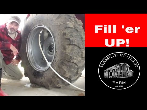 In the case of very little ballast, the tire tread marks will not be visible due to tire slip.
Front end weights (if fitted)
Front end weights can be attached to the tractor using the weight frame. Weights and a weight frame are available from your dealer. The cargo frame is equipped with weights, the number of which reaches up to 9, or up to 6. There is also a cargo with an earring. Each weight weighs 45 kg (100 pounds), the weight with the earring weighs 100 kg (220 pounds).
Use front end weights when you need good steering control and front end stability, and when you want to get the best working efficiency and performance from your tractor. See Tractor Weight Distribution on page 159 for recommendations on ballasting procedures.this guide.
IMPORTANT: The total weight of the tractor with all equipment and ballast weight must never exceed the maximum recommended operating weight. See "Maximum Operating Weights" on page 249 of this manual. Follow the recommendations for tire capacity, as well as any other possible restrictions established by law.
Installing front end weights
STEP 1
Park the tractor on hard, level ground, apply the parking brake and stop the engine. nine0005
STEP 2
If a clevis weight (2) is to be installed, fit the clevis weight and head pin with cotter pin (3). Make sure the stopper of this pin (A) is installed correctly in the top hole (B) of the head pin with cotter pin hole (3).
STEP 3
Hang one weight (4) on the hook so that it is over the top ledge of the weight frame (1) towards the outer edge (as shown in the photo above). nine0005
STEP 4
Move the weight (4) towards the center of the frame (1), next to the weight with clevis (2) (if provided), or move until it is against the lug (D) located on the weight frame (1). The lower part of the weight (4) will lock behind the lug (E) located in the center of the weight frame (1).
Repeat STEP 4 place the second weight on the outside of the clevis weight (2) or lug (D) on the weight frame.
IMPORTANT: If the eyelet weight (2) is NOT to be installed, the minimum number of weights (4) that can be installed is TWO, one on each side of the lug (D) found on the weight frame (1). The protrusion on one weight (4) must fit into the cavity (C) present in the weight previously installed in STEP 4.
STEP 6
the required set of weights is installed. The protrusion (F) on each weight will interconnect by inserting into the previously installed weight. nine0005
STEP 7
Install the mounting pin (5) inserted into the holes provided in the weight set and install the threaded plate (6).
Make sure the threaded connections are fully seated in the plate and that the plate fits correctly into the recess made in the outer weight (4). Install washer (7) and nut (8) on opposite end of stud (5). Tighten the nut.
STEP 8
If shorter studs (6) are used, install a stud on each side and use two plates (5) as shown. nine0005
STEP 9
If a small number of weights are to be installed, install and tighten the appropriate bolt through the weights into the threaded plate. Make sure the screwed plate fits into the recess provided in the weight.
Ballast weights to increase rear wheel load
Ballast weights to increase rear wheel load are available from your dealer depending on the market. Two types of weights can be attached to the wheels of the CX series tractor. There are HALF TYPE weights (consisting of two halves), weighing 34 kg (75 lbs) per pair, or SOLID TYPE, weighing 54.5 kg (120 lbs). They can attach to wheels up to 42 inches in diameter. nine0005
TWO BALLAST WEIGHT
SOLID TYPE BALLAST WEIGHT
Use wheel weights when the tractor is required to operate safely and efficiently. Do not add more weight to the rear wheels of your tractor than is required to achieve the correct static weight distribution of the tractor and the correct amount of wheel slip.
Refer to Tractor Weight Distribution on page 159 for recommendations on ballasting procedures.this guide.
IMPORTANT: Raise the rear wheels off the ground and rotate the wheels 180 degrees for each set weight, changing the position of each weight to get the correct balance alignment. A maximum of 3 weights per wheel can be used. These 3 weights can be mounted on the inside or outside of the wheels.
IMPORTANT INFORMATION: Gr ties can only be attached on the inside or on the outside, not both. The inner weights must not extend over the cast axle housing. nine0005
IMPORTANT: Wheel weights CANNOT be used when dual wheels are fitted. Liquid weights can only be added to the inner wheel. In addition, weights can also be installed at the front end.
IMPORTANT: The total weight of the tractor with all equipment and ballast weight must never exceed the maximum recommended operating weight. See "Maximum Operating Weights" on page 249this guide. Observe tire load capacity recommendations and any other legal restrictions.
Liquid Tire Ballast
Use Liquid Tire Ballast when tractor operation is required to be safe and efficient. See Tractor Weight Distribution on page 159 of this manual for recommendations. The table shows the liquid ballast that will be contained inside each tire when it is 75 percent full (the ballast is filled to the level of the tire valve) with water or a solution of calcium chloride with water. nine0005
Calcium chloride prevents water from freezing. Water starts to freeze at 0°C (32°F).
When using liquid ballast, inflate tires 0.14 bar (2 psi) above recommended pressure. This will compensate for the aeration that occurs when the tire is in motion.
When twin wheels are fitted, use liquid ballast on the inner wheels only.
IMPORTANT: The total weight of the tractor with all equipment and ballast weight must never exceed the maximum recommended operating weight. See "Maximum Operating Weights" on page 249this guide. Observe tire load capacity recommendations and any other legal restrictions.
| The amount of liquid ballast per tire is in liters and kilograms | |||||||||
| Tire size | only water | 1 kg CAS1 904 1.6 kg CaCl 2 for 4.5 liters of water | 2.3 kg CaCl | ВЕС, кг | ВОДЫ | кг | |||
| 11.2-24 | 91 | 91 | 83 | 103 | 76 | 107 | 72 | 115 | |
| 12. | 113 | 113 | 0061 132 | 98 | 140 | 95 | 151 | ||
| 13.6-24 | 144 | 144 | 129 | 160 | 121 | 172 |
| 181 | |
| 18.4-26 | 299 | 299 | 276 | 342 | 257 | 365 | 242 | 387 | |
| 14. | 182 | 182 | 163 | 205 | 154 | 216 900 900 | 145 | 232 | |
| 14.9R30/14.9-30 | 189 | 189 | 163 | 205 | 154 | 216 | 145 | 232 | |
| 16.9R30/16.9-30 | 277 | 277 9000 | 254 | 315 | 236 | 339 | 227 | 357 | |
| 18. | 336 | 336 | 309 | 384 | 290 | 414 | 272 | 436 9000 9000 9000 | |
| 0062 12.4R32/12.4-32 | 131 | 131 | 122 | 154 | 118 | 165 | 113 | 181 | |
| 16.0062 376 | 250 | 402 | |||||||
| 18.4R34/18.4-34 | 378 | 378 | 344 | 427 | 322 | 456 | 306 | 490 | |
| 12. | 140 | 140 9000 | 0061 154 | 118 | 165 | 113 | 181 | ||
| 13.6R36/13.6-36 | 182 | 182 | 163 | 205 | 154 | 216 | 145 | 232 9000 9000 | |
| 13.6R38/13.6-38 | 213 | 213 | 195 | 244 | 186 | 264 | 172 | 280 | |
1. Water will freeze at 0°C (32°F).
2. A solution containing 0.91 (2 lb) calcium chloride solution per 4.5 liters (1.2 US gal) of water will provide protection down to -8°C (+13°F) and will freeze at -31°C (-23°F). nine0005
3. A solution containing 1.59 (3.5 lbs) of calcium chloride per 4.5 liters (1.2 US gal) of water will provide protection down to -26°C (-12°F) and will freeze at -47°C (-52°F).
4. A solution containing 2.27 (5 lbs) of calcium chloride per 4.5 liters (1.2 US gal) of water will provide protection down to -47°C (-52°F) and will freeze at temperature -54°C (-62°F).
5. 4.5 liters (1.2 US gal) of water weighs 4.5 kg (10 lbs). nine0005
NOTE: DO NOT use radiator type antifreeze in tires.
Filling procedure
STEP 1 (mixing solution)
Add the correct amount of calcium chloride to the correct amount of water, see the previous table to ensure the required degree of frost protection.
WARNING: SLOWLY add calcium chloride to the water, stirring constantly. NEVER ADD WATER TO CALCIUM CHLORIDE. If this is done, a violent reaction will occur. With proper mixing, the temperature of the solution will rise. Allow the solution to cool before adding to the tire. For details of the procedure, contact your authorized dealer. nine0005
STAGE 2
Raise one side of the tractor and turn the wheel so that the tire valve is at the top, see illustration opposite.
STEP 3
Remove the tire valve stem and attach the hand pump.
STEP 4
Measure the amount of solution added to the tire and use the numbers in the previous tables to calculate the added weight.
STEP 5
When sufficient weight has been added, remove pump, insert valve stem, inflate tire to correct pressure. nine0005
NOTE: When using liquid ballast, inflate tires 0.14 bar (2 psi) above recommended pressure. This will compensate for the aeration that occurs when the tire is in motion.
435/485/535
3-95
3 F3-131
Standard
4
4
4
For triple wheel configuration, fitting
a.
inner wheel only allowed with rim
inward (narrow track width)
Place block of wood with thickness 51-
b.
76 mm for the wheel to be built.
20 nuts (1) hold inner wheel for
c.
hub. Remove 18 of the 20 nuts from the wheel leaving
2 nuts (2) 180° removed as shown in
figure. They hold the rim on the hub and
go into grooves (3) on the rim of the middle wheel.
Carefully select the remaining two
nuts so that the nipples (4) of the tires
of both wheels are accessible, to facilitate subsequent
tire pressure maintenance.
With the help of a suitable hoist
d.
lift the middle wheel rim and guide it
onto the studs. Make sure that two grooves (3) on the rim
of the middle wheel match the two nuts
left on the rim of the inner wheel.
DANGER: TWIN AND TRIBE
DRUM WHEELS EXTREMELY
HEAVY. THEY EASILY TIP INTO THE
DRUM SIDE OF THE WHEEL. USE
RELATED
LIFT
AND
SAFETY CHAINS FOR
DRUM TYPE WHEELS.
NOTE: Do not interchange
middle wheel and outer wheel. The middle
wheel has a plate (5) welded into the inner diameter
for mounting the outer disk
of the wheel.
NOTE: Install the wheels
in such a way that the inner and
of the middle wheel were directed in the same direction and
in the same direction.
NOTE: Install the middle wheel
so that the tire nipple is
in line with the tire nipples of the inner and
5 outer wheels
Replace the 18 nuts (1) previously removed
e.
(see step "c").
Tighten the wheel nuts to 710 Nm. nine0005
f.
With appropriate lift
g.
lift the outer wheel and guide it
into the middle wheel. Align holes in
center wheel plate with holes in
outer rim.
Section 3 - Principle of Operation
Wheel Installation - Triple
F4-65
11
2
3
0002 34
3-96
435/485/535
Note: install wheels like
in the way, so that protectors of the average and
of the outer wheels are sent in one and
the same direction.
Install twenty fixing screws (6),
h.
washers and nuts through wheel rims. Tighten nuts
to 710 Nm.
NOTE: The middle and outer
wheel rims have large openings to facilitate
mounting of the disc mount.
Repeat these steps for the other three
i.

 This will be approximately 75%. The 3 pound calcium chloride per gallon of water solution is slush-free to -12F and solid at -52F. 5 lb/gal solution is slush-free to -53F and solid at -63F.
 00-12
00-12 00-14
00-14 00-16
00-16 1
1 2-30
2-30 5-42
5-42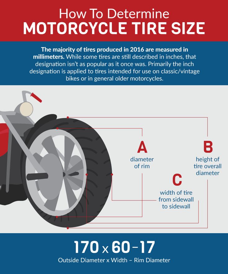 2-36
2-36 4-28
4-28 6-28
6-28 9-28
9-28 9-26
9-26 5L-24
5L-24 4-30
4-30 8-34
8-34 1-30
1-30 5L-32
5L-32 4-24
4-24  9r28/14.9-28
  4R30/18.4-30
 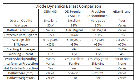 4-36
4-36