H-TL-633
Haltec Valve Cap Remover For Dual Wheels - (8.25"L)
$21.15
1 reviewAME-51025
AME 51025 QVC Quick Valve Change Tool
$37.95
11 reviews44-413-EA
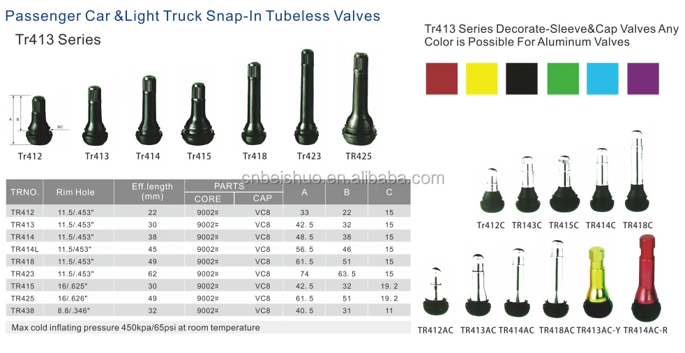
AA TR-413 Snap-In Tubeless Valve (.453" RH)
From $0.28
5 reviews43-303
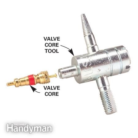
AA 11" Extra-long Valve Core Remover (Ea)
$10. 76
H-310
Haltec 310 Valve Adapter Gun, Core Ejector for Liquid Filled Tire
$105.00
44-572-90
AA Pre-Bent TR-572 Clamp-In Tubeless Truck Valve (Ea)
From $2.50
LVT050
Rema Lock-on Valve Core Tool for Car/LT
From $18.98
ALI-V2B-10
Alligator V2B Gator Double Seal Tire Valve Caps
From $11.95
43-025
AA Valve Core Fuel Rail (Viton) (Box of 10)
$10.95
3 reviews43-122
AA Metal Truck Valve Extension (ea. )
)
From $7.98
44-543-EA
AA TR-543 Clamp-In Valve For Alcoa Wheel (0.389" RH) (Ea)
From $1.95
1 reviewM-443
Milton Combination Valve Core Extractor + Installer + Inflator Tool
$19.25
2 reviewsH-P15
Haltec 5/8" Rubber Rim Hole Plug for Tube-Type Wheels (Ea.)
$3.76
2 reviews43-098-10
AA Double Seal Valve Cap
From $9. 95
95
43-160
AA Slip-On Valve Stem Puller
$2.00
44-600-EA
AA TR-600HP High Pressure Snap-In Tire Valve (0.453"RH)
From $0.95
1 reviewLN-10-P
AA Rim Nut for Air/Liquid Valves TR218A, TR220A (Ea)
From $0.95
1 review44-416MC
AA 2.25" Bent Brass Valve For Ford F-Series
From $3.50
44-572-EA
AA TR-572 Tubeless Truck Tire Valve (. 625" RH)
From $1.95
DIL-VS-3600
Dill VS-3600 Sprinter Dually Valve for Outer Rear Steel Wheel (Ea)
From $18.00
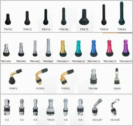
All Metal Valve Stems1147115ms115ms2713 Degree Bend13 Degrees13°13° Bend16 Degree Bend16 Degrees16°16° Bend23 Degree Bend23 Degrees23°23° Bend27 Degree Bend27 Degrees27°27° Bend3 Valve Stems & Hardware3.1 Metal Valve Stems3.1 Valve Stems3.12 Metal Passenger3.13 Metal Truck3.16 Tank31 Degree Bend31 Degrees31°31° Bend399400401416416L416mc41741MS41ms0043045 degree45 Degree Bend45 Degrees45°45° Bend47501OV509510511513515523MS542543544544D545545D545E546546D546E552554554D555D575575A575hp60 Degree Bend60 Degrees60086010602060306040605060ms60ms2760°60° Bend618618A621621A622622A623623A65 Degree Bend65 Degrees65°65° Bend70ms70ms2770ms775 Degree Bend75 Degrees75°75° Bend80ms80ms2790 degree90 Degree Bend90 Degrees90ms90ms2790°90° BendAir LiquidAir Liquid ValveAir Liquid Valve StemsAlcoaAlcoa Grommet Seal Valve StemAlcoa Grommet Valve StemsAlcoa O-Ring Seal Valve StemAlcoa O-Ring Valve StemsAluminumAluminum Truck Valve StemAluminum Wheel Tubeless Valve StemsBend_13°Bend_16°Bend_23°Bend_27°Bend_31°Bend_45°Bend_60°Bend_65°Bend_75°Bend_90°Bend_Double BendBend_StraightBrass Tubeless Clamp-In ValvesChromecircularClamp-In Valve StemDouble BendDouble Bent Valve StemDouble Bent Valve Stemsds1duallydually valve stemdually valve stemsdully valve stemdully valve stemsEinkyenkeiEnkei Valve StemsFlush Mount Valve StemsFor_PassengerFor_TankFor_TruckFordFord F Series Valve StemFord F Series Valve StemsH-47H-501OVH-523MSHigh Pressure Chrome Valve StemsisuzuizuzuLight Alloy Valve StemsLow Profile Chrome Valve StemLow Profile Chrome Valve StemsMetal Tubeless Clamp-In ValvesmetricMetric Rim Hole Valve StemMetric Rim Hole Valve StemsMotorcycle ValvesN-1147N-1600N1147N1600oblongovalOval Rim Hole Valve StemsPassengerrim holeSpecial Clamp-In ValvesStraightStraight - No BendTankTank ValveTank ValvesTR416TR416DS1TR416LTR416MCTR417TR430TR500TR501TR501-OVTR509TR510TR511TR513TR515TR542TR543TR543CTR543DTR543ETR544TR544DTR545TR545DTR545ETR546TR546DTR546ETR552TR554DTR555TR555DTR570TR575TR575ATR575HP-DS1TR618TR618ATR621TR621ATR622TR622ATR623TR623Atractor valveTruckTubelessTubeless Truck Valve StemTV-399TV-400TV-401TV-416TV-416-DS1TV-416LTV-416MCTV-430TV-500ATV-501ATV-509TV-510TV-511TV-513TV-515TV-542TV-543TV-543CTV-543DTV-543ETV-544TV-544DTV-545TV-545DTV-545ETV-546TV-546DTV-546ETV-552TV-554DTV-555DTV-570ATV-571ATV-572-13TV-572-F19TV-572ATV-573ATV-574ATV-575-HPTV-575-HP-DS1TV-575ATV-6008CTV-6010TV-6020TV-6030TV-6040TV-6050TV-621ATV-622ATV-623ATV-714TV-CPVtv416TV416LTV430tv500tv501tv509tv510tv511tv513tv515tv543tv543ctv543dtv543etv544tv544dtv545tv545dtv545etv546tv546dtv546eTV552tv554tv554dtv555tv555dtv570tv571tv572atv573TV575TV575HPtv60008TV6010TV6020TV6030TV6040TV6050TVCPVType_Air Liquid ValveType_Alcoa Grommet Seal Valve StemType_Alcoa O-Ring Seal Valve StemType_Aluminum Truck Valve StemType_Clamp-In Valve StemType_Double Bent Valve StemType_Ford F Series Valve StemType_Low Profile Chrome Valve StemType_Metric Rim Hole Valve StemType_Tubeless Truck Valve StemV3-20-1valve stemVH515-4
FeaturedBest SellingAlphabetically: A-ZAlphabetically: Z-APrice: Low to HighPrice: High to LowDate: New to OldDate: Old to New
 Diagnostics and repair of trailers and semi-trailers.
 1 All repairs and modifications to the trailer must comply with the requirements of the Transportation (Transportation Standards) Regulations 1990 and Amendments.
2 All beam, tie rod, and cable welding must comply with NZS 5446 1987 and be performed by a person holding a current NZS 4711 welding certificate. nine0003
4 The following legislation and amendments must be followed for consultation:
- Health and Safety at Work Act, 1992.
5 Reference to suitable tools and equipment means industry-approved tools and equipment that are recognized by the industry as best suited to perform the task in a professional and competent manner with due regard to safe working practices.
6 Because of the special nature of this reference standard, it is critical that practical evaluation data be obtained from commercial workplaces in the workplace under normal workplace conditions. nine0003
Results and evidence requirements
Demonstrate knowledge of trailer and semi-trailer.
Evidence requirements
1.1 Semi-trailer and trailer vehicle configurations are described in accordance with manufacturer's specifications.
1.2. Tractor trailer hitch systems are described in accordance with the manufacturer's specifications.
Range two axles, three axles, four axles.
1.3 Semi-trailer axle systems are described in accordance with the manufacturer's specifications. nine0003
Single axis, two axis, three axis range.
1.4 Tractor trailer and suspension semi-trailers are described in accordance with the manufacturer's specifications.
Range of single axis, short range and wide range tandem, short range and wide range triaxial.
Demonstrate knowledge of trailer and semi-trailer braking systems.
Evidence requirements
2.1 The operation of the trailer and semi-trailer braking system is described in accordance with the manufacturer's specifications. nine0003
Air lines with air flow, air supply and storage system, automatic drain valve, brake chamber, control valve, spring brake, switch-off valve, tractor safety valve, pneumatic trailer clutch, pneumatic leveling system.
Demonstrate knowledge of trailer and semi-trailer steering systems.
Evidence requirements
3.1 Trailer towing and turning systems of tractors are described in accordance with the manufacturer's specifications. nine0003
Vertical rotary tables, rods.
3.2. Semi-trailer turntables are described according to the manufacturer's specifications.
Friction type, anti-friction type;
semi-oscillatory, compensating.
3.3. Trailers and locking devices are described in accordance with the manufacturer's specifications.
3.4 The tipping trailer homing device is described in accordance with the manufacturer's specifications.
3.5. The self-steering axle of a tipper trailer with a semi-trailer is described in accordance with the manufacturer's specifications. nine0003
Further steering, steering and damping, reverse blocking.
Determine the need for maintenance and repair of trailers and trailers with air brakes._01.jpg)
Evidence requirements
4.1 Safe working practices are followed throughout the task.
Personal safety range, safety of others, equipment safety.
4.2 The operation of the trailer-semi-trailer braking system is checked in accordance with the instructions of the manufacturer's manual and any faults found. nine0003
4.3 Brake pads, springs, backplates, operating mechanisms, brake drums, tensioners and brake chambers are checked and any faults found.
Range wear, clogging, runout, distortion, friction lining condition, spring brake operation.
4.4 Air brake components are inspected on site and noted for any signs of air leakage and damage.
Condition of a range of pipes and hoses, seams, cylinders and valves. nine0003
4.5 Steering and turntable steering maintenance schedules are checked and steering systems are checked for wear and damage and results noted.
Long range clutch, turntables, friction plates, tie rods, turntables, locking device.
4.6 Checked for wear and damage to the self-loading oscillating axle and found faults.
Range ring pins, traction arm, damping control, reverse lock, wheel alignment. nine0003
Repair trailer hitch and semi-trailers.
Evidence requirements
5.1 Safe working practices are followed throughout the task.
Personal safety range, safety of others, equipment safety.
5.2. Appropriate tools and equipment are selected and used to enable corrective work to be carried out.
5.3 Errors noted in the air brake equipment are corrected in accordance with the manufacturer's requirements and the New Zealand Heavy Vehicle Code. nine0003
Spring brake range, tractor safety valve, switch-off valve, automatic drain valve, air hoses and lines.
5.4 Wheel stations are dismantled, repaired and reassembled in the order and sequence prescribed by the manufacturer to ensure full functionality and compliance with the manufacturer's specifications.
5.5 Brake shoes and tensioners are adjusted according to the manufacturer's requirements.
5.6. The brake system is checked for errors. nine0003
Service and repair trailer and semi-trailer suspensions.
Evidence requirements
6.1 Safe working practices are followed throughout the task.
Personal safety range, safety of others, equipment safety.
6.2 The trailer and semi-trailer suspensions are checked for misalignment, wear and damage and any defects noted.
Coil springs, air springs.
6.3 Any misalignment, wear and damage to the suspension system shall be repaired by replacement with manufacturer approved replacement parts. nine0003
Radial spring sheets, shackles, hangers, equalizer rods, torque rods, air bellows, equalizer valve and related equipment, shock absorbers.
Check and adjust trailer wheel alignment.
Evidence requirements
7.1. Safe working practices are followed throughout the task.
Personal safety range, safety of others, equipment safety.
7.2 Suitable tools and equipment are selected and used to check the alignment of the trailer wheels. nine0003
7.3 The alignment of the semi-trailer wheels is checked in accordance with the method prescribed by the manufacturer of the alignment equipment and any misalignment is noted.
7.4 Adjustments are made to align the wheels to bring it back to full working order as prescribed by the trailer manufacturer.
Contents
The gas distribution mechanism of the KamAZ engine has a number of key parts. Consider the typical defects of each and how to eliminate them. nine0003
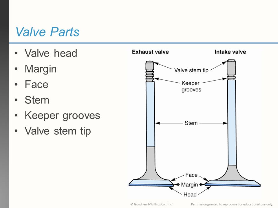
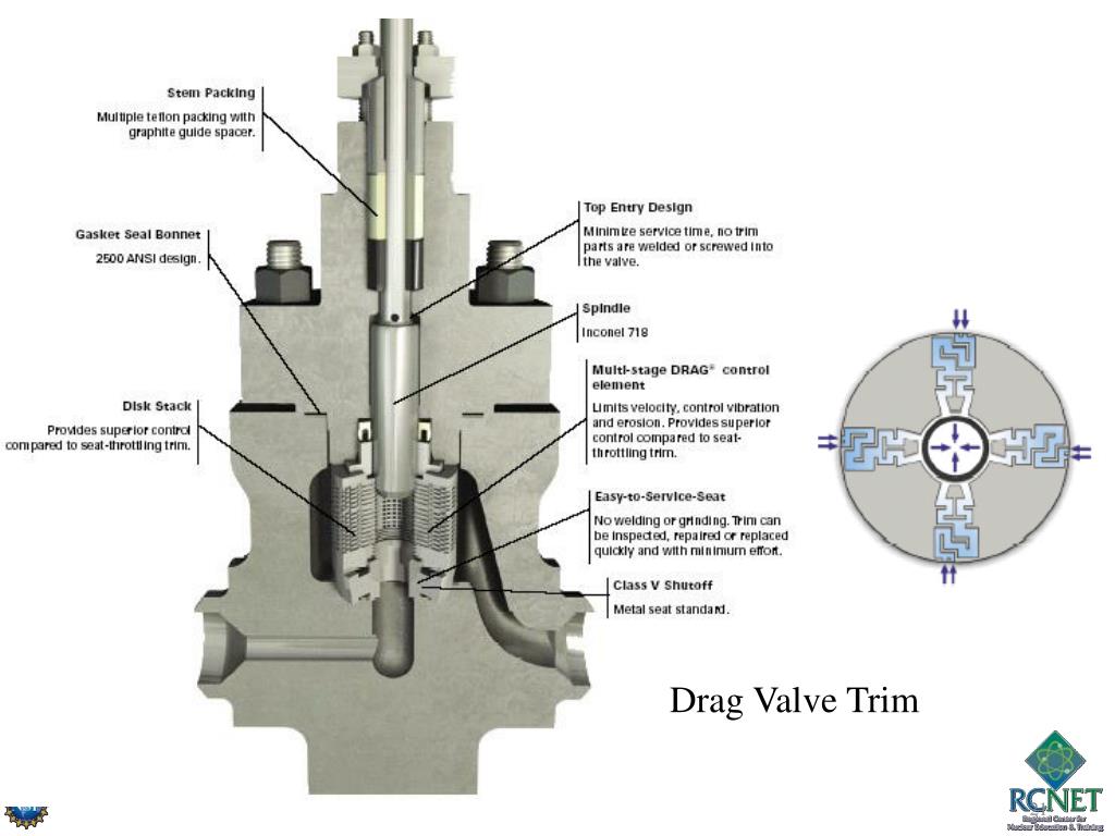
Valves made of heat resistant steel. The valve stem is graphitized before installation. Valve face angle 45°; exhaust valve diameter 51.5 mm, inlet - 46.5 mm; valve lift 12.5 mm.
Characteristic valve defects are wear of the working chamfers, bent stem, breakage of the valve disc.
Poppet type pushers, steel, poppets are hardfaced with chilled cast iron. The characteristic defects of the pushers are the wear of the plate, the sink on the working surface, the wear of the rod. nine0003
Worn out plates and push rods are restored by chrome plating.
After reconditioning, the valves are ground in the cylinder head seats.
Valve lapping begins with the preparation of a paste: the paste is prepared from 1.5 parts (by volume) green silicon carbide micropowder, one part diesel oil and 0. 5 part diesel fuel. Before use, the lapping paste is mixed so that the micropowder does not precipitate. A thin, even layer of paste is then applied to the face of the valve seat. The valve stem is lubricated with engine oil. Grinding is performed by reciprocating rotational movement of the valve with a drill with a suction cup or an appropriate device. While pressing the valve, it is necessary to turn it 1/3 turn clockwise, then 1/3 turn in the opposite direction. Valves are not rubbed in a circular motion. Lapping continues until a belt with a width of at least 1.5 mm of a matte color appears on the chamfers of the valve seats, as shown in fig. 51.
Fig. 51. Location of lapped matte bands on the seat and valve head in the closed position:
a - correct; b - wrong; I - position of the band on the valve seat and head
When properly lapped, the matte band on the valve head seat should start at the larger base of the seat cone.
After lapping, the valves and cylinder heads are washed with kerosene and blown with air. The quality of valve grinding is determined after assembling the valve mechanism by checking it for leaks. To do this, the cylinder head is installed with the inlet and outlet windows up and diesel fuel is poured into the recesses of the valve seats. Well-lapped valves should not allow fuel to pass through the sealing points for 30 minutes. When kerosene leaks, a rubber hammer is tapped on the end of the valve. If the leakage is not eliminated, the valves are rubbed again. nine0003
If necessary, the quality of lapping is checked “by pencil”. To do this, 6-8 dashes are applied at an equal distance to the valve chamfer with a soft graphite pencil. The valve is carefully inserted into the seat and, after pressing firmly, turns 1/4 turn. With high-quality grinding, all lines should be erased.
After checking the lapping, the valve train is assembled and adjusted. The valves are adjusted at four positions of the crankshaft. The first position of the crankshaft is determined relative to the start of fuel injection into the first cylinder by combining the marks on the injection advance clutch and the fuel pump housing. nine0003
The camshaft is hot stamped from 18KhGT steel. It is installed in the collapse of the block on 5 support bearings. The surfaces of bearing journals and cams are hardened by high-frequency currents after carburizing. The surfaces of the journals and cams are precisely machined: they are ground, polished and then phosphated. The runout of the surfaces of the second, third and fourth necks relative to the axis of the extreme necks is allowed no more than 0.025 mm. The non-cylindricality of the bearing journals is 0.005 mm, the non-parallelism of the generatrices of all cams relative to the surface of the extreme journals is not more than 0.05 mm. nine0003
A forged steel gear with straight teeth is pressed onto the rear end of the camshaft. The gear teeth are heat treated. The camshaft gear is driven through the intermediate gear by the crankshaft gear.
Characteristic defects of camshafts are:
The gas distribution mechanism shown in fig. 48, includes camshaft, tappets with guides, rods, head cover gasket, rocker arms with adjusting screw, valves with two valve springs, valve guide and valve holder. The valve mechanism is closed by a cover. The covers are bolted to the cylinder heads.
Fig. 48. Gas distribution mechanism of the KamAZ-740 engine:
1 - camshaft; 2 - pusher; 3 - pusher guide; 4 - rod; 5 - head cover gasket; 6 - rocker; 7 - nut; 8 - adjusting screw; 9 — a bolt of fastening of a cover of a head; 10 - cracker; 11 - plate bushing; 12 - spring plate; 13 - outer spring; 14 - internal spring, 15 - valve guide; 16 - washer; 17 - valve; A - thermal gap between the toe of the rocker arm and the valve stem
49. Disassembly of the valve mechanism using the device I-801.06.100:
1 - screw; 2 - handle; 3 - plate; 4 - pin; 5 - base; 6 — traverse of tool
49. To disassemble the valve mechanism, it is necessary:
Steel push rods, hollow, with inserts, tips. A characteristic defect of the rods: the weakening of the fit of the tips and the curvature of the rod rod.
Each valve has two springs. In accordance with the requirements of the technical specifications for the control, sorting and restoration of springs, the pre-set spring force should be 360 N, and their total working (in a compressed state) force should be 830 N. If the springs are defective, about 10% of the total number is rejected. Instead of rejected springs, new ones are supplied to the assembly of the gas distribution mechanism. nine0003
The dimensions of the cams and bearing journals of the camshaft are checked using the tool shown in fig. 50, and the dimensions of the cams are shown in table. 28.
Technological conditions for control, sorting and restoration of camshafts are presented in table. 29.
50. Tool for checking the profile of the cams and bearing journals of the camshaft:
a - cam profile, b - location of intake cams; in - the location of the final cams; Vp - inlet cam; Vyp - final cam; 1 - the base of the device; 2.9 - centers; 3 — disk with graduation, hail; 4 - index arrow fixed on the neck of the camshaft; 5 - indicator leg; 6 - indicator stand; 7 - indicator, 8 - camshaft
The camshaft control sequence is as follows:
 929
929 Note: a - cam angle; h is the lifting height of the cam profile.
Non-compliant camshafts are remanufactured.
Part no. 740.1006015.
Material: steel 18KhGT
 10
10  025
025 Camshaft reconditioning process includes the following operations: camshaft washing, gear removal, camshaft straightening and runout checking, shaft journal grinding to repair size, journal size control, cylinder cam grinding, control cam profile, making a groove for the key, installing gears, handing over the camshaft to the Quality Control Department.