I’ve heard that it’s not very safe to drive on a plugged tire. Is that true? Why is repairing or replacing a damaged tire a better option than plugging a tire? What are the dangers of driving on a plugged tire?
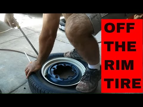
We’ve all been there before. You wake up or walk to your car after work, only to look down and see a flat tire and a nail sticking out. You don’t have time to take your vehicle into an auto shop and need a quick fix. It’s a small nail, so you plug your tire and go on with your life.
You only meant for the plug to be a temporary solution until you could get the tire replaced. Then life happens, and it’s a few days before you can get a new tire. Those few days turn into months, which can quickly turn into a year. You may start to ask yourself if it’s really safe to drive on a plugged tire.
It turns out that installing a plug can have a serious impact on the life and integrity of your tire. That is if it’s safe to plug your tire at all. Here is what you need to know about plugged tires and how safe it really is to drive on one.
The first thing you should consider when plugging a tire is if it’s safe to install a plug in the first place. There are specific cases when it’s safe to use a plug. Outside of these scenarios, driving on a plugged tire could be dangerous to you and other drivers.
Depending on the size of the puncture, the extent of the damage, and the tread of your tire, you may not be able to repair the tire with a plug. The size of the hole must be no larger than 0.25 inches and must be located on the tread of your tire. If the puncture is on the shoulder or sidewall, then you will need to replace the tire.
The angle of the puncture also makes a big difference in the effectiveness of a plug. Ideally, the nail or object that punctured your tire went straight in. This would make a repair fairly straightforward. However, if the tire was punctured at an angle, the plug will have a hard time completely sealing the punctured area. Take note of how the nail or screw looks and the angle that it entered the tire.
The age and quality of your tire is also an important factor in whether or not it can be plugged. If the tread on your tire has been worn below 2/32 of an inch, then your tread is too far gone to be plugged. If you’re wondering how you can measure this, 2/32 of an inch is the amount measured by the classic penny test. Make sure your tire passes the penny test before you even thinking of plugging it. If it doesn’t pass the test, then it’s probably time for a new set of tires anyway.
If you have to ask yourself whether or not your tire can be repaired, that may be a sign that it’s time to move on. A TIA-certified tire technician can inspect your tire and let you know for certain if it’s safe.
Another thing to think about when it comes to driving on a plugged tire is how your repair may impact the manufacturer’s warranty on your tire. Improper repair and maintenance is a surefire way to void your warranty. Think twice the next time you consider opting for a DIY approach on your next tire repair.
When it comes to the safety of your vehicle, it’s always best to leave things to the experts. By having your tire repaired by a certified professional, you can be confident your repair is performed properly, and your manufacturer warranty is still “good.”
The biggest problem with driving on a plugged tire is that you still have a hole in your tire! While it may be a temporary fix, it’s important to recognize that there is still a structural failure in your tire that needs to be addressed.
It only makes sense that a plugged tire cannot handle the same level of stress and strain as a tire in good condition. This is especially true when you start reaching higher speeds on the highway. The manufacturer won’t support a tire’s speed rating once it has been repaired. So, if you plan on racing, off-roading, or just want to go fast, a plugged tire isn’t going to work.
Over time, it’s possible for that small puncture to slowly get larger. This results in a greater loss of air while also increasing your chances of a blowout on a road. Furthermore, the plug itself may fail while you are driving, putting you back where you started.
In the event of a flat tire from a nail or screw, the best course of action is always to replace the tire. A plug or patch for your tire may help tide you over until you can have it replaced, but it’s important to remember that a plug is meant to be a temporary fix.
While it may be tempting to see how far you can get with a five-dollar repair, the consequences of a plugged tire failing will be much worse than if you had replaced the tire in the first place.
If you just purchased a tire or recently bought a set of expensive tires, it can be a frustrating experience. If this is the case and you hope the tire can be saved, it may be worth it to have it inspected by a professional.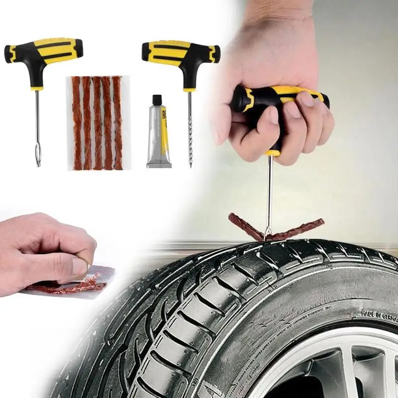
The TIA-certified tire experts at Tread Connection know how to properly diagnose, inspect, and repair flat tires. When you work with Tread Connection for your flat repair, the tire will be removed from the wheel and carefully inspected inside and out. This helps us ensure whether or not it can be safely repaired.
If the tire can be repaired, our team will take care of it for you. In the event that your tire cannot be safely repaired, our team will recommend a replacement from our wide range of tires to find the right one for your needs, and your budget.
It’s never worth it to gamble when it comes to the safety of you and your vehicle. Don’t try to see how long you can drive on that plugged tire. Have your tire inspected and repaired the right way by the TIA-certified tire experts at Tread Connection.
We bring the tire shop to you and can repair your flat or replace your tire at your home and on your schedule. Schedule your tire service with Tread Connection today!
BUY TIRES
Home » Tire Patches vs. Tire Plugs: Which Is Better?
What are tire patches and tire plugs? Well, they are useful when you get a flat tire. In such cases, there’s a good chance that a minor repair can get you back up and running again quickly.
Three of the most common of these “minor repairs” are:
The first option, a tire plug, is cheap and fast to administer. Plugs work best when you’ve run over a nail or similar blunt object that punctures the tire and causes it to leak air. After the nail or sharp object is removed, the plug can be inserted into the hole to fix the leak. While plugs of the old days were problematic and served more as a band-aid type of repair than anything else, many plugs available today actually vulcanize to the tire to provide better stability.
A patch, on the other hand, is considered to be a better quality tire repair. However, it’s a bit more laborious of a repair than a plug. Patching a tire actually consists of removing the tire from the rim and then using a die grinder to clean up a 2-inch diameter around the puncture to give the patch enough of an area to bond with. The patch is then pushed from inside the tire through the outside of the tire, sealed, and let dry.
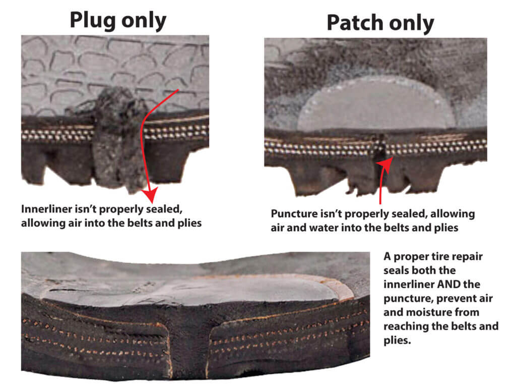
The best modern tire repair solution is a plug/patch combo product. This is one piece and it combines the best benefits of both options.
Keep in mind that not all tire damage can be repaired. For example, tire bubbles are a dangerous problem that will result in needing new tires.
The question is: Can or should you repair a tire on your own?
If you purchased your tires from a mechanic or tire-specific business, then chances are they will either plug or patch your tire for free if it develops a leak and a patch or plug can resolve the issue.
Many tire-specific businesses will also fix your tire via these means as a way of developing goodwill with you, the customer, so that when it comes to buying new tires you’ll consider purchasing that next set from them.
However, outside of these two scenarios, tire patching and plugging aren’t necessarily expensive (usually only $10-$20 a repair), but more of an inconvenience.
Considering this, patching your tires on your own might not be worth it.
DIY patching or plugging is still an option, yet we’d advise you to be absolutely sure of what you’re doing before going the patching route.
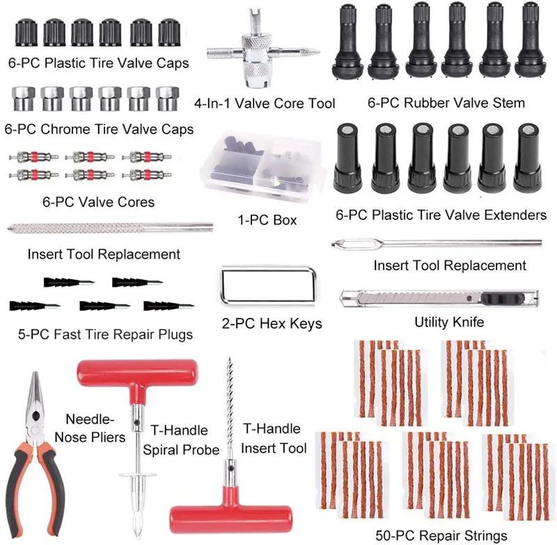
The plugging route is fairly simple (and cheap, as plug kits can be purchased for just a few dollars), as all you really need to do is locate the hole and insert the plug. Going the patching route is also fairly inexpensive, but there’s a lot more involved.
For instance, patching a tire consists of:
Plugs won’t usually work when a puncture is near the sidewall, as it likely won’t be able to completely seal the area. Plugs are also ineffective when the puncture is on an angle. Patches are usually the better-recommended option, but they do have their limitations. For instance, if a puncture is greater than a quarter-inch in diameter, a patch will likely be ineffective and the tire may be too damaged to repair.
Plugs, when installed correctly and in the right situations, can help a tire last for up to 25,000 additional miles. But while plugs can be effective, usually patches are considered to be the better, more secure option of the two. The patch/plug combo is the safest and most reliable option.
Are plugs just band-aid repairs?Yes and no. Years ago they were and if they aren’t installed correctly or in the right situations today, they still are. However, today’s plugs vulcanize to the tire and can help it last for tens of thousands of miles more.
Hello, dear readers of the Electrician's Notes website.
After writing an article about connecting circuit breakers, I began to receive letters in the mail asking me to tell more about the connecting busbars for automatic switches. The people call them simply "combs", and in the manufacturers' catalogs there is a name - a comb or distribution bar.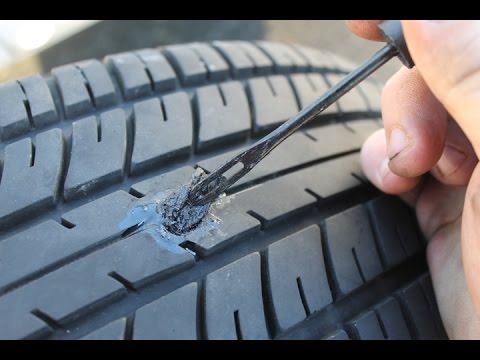
For example, in your apartment panel, several single-pole group automats are installed in one row.
The power supply of the apartment is single-phase, so we need to supply the supply (of the same name) phase to all machines.
There is a standard and common option - using a wire of the PV brand (you can use at least a rigid PV-1, at least a flexible PV-3) to make jumpers and connect the machines with a loop.
Ignore the color of the wires - this photo is taken as an example.
I have nothing against this method - everything is quite simple, and most importantly reliable, but from the point of view of convenience and aesthetics, there are some drawbacks:
 )
) Personally, I still assemble small shields using this method. But if the shield is large enough and there is free money, then the best option would be to use connecting tires (combs), although you will need to figure out their designation and marking in advance in order to buy what you need.
Combs are divided according to the number of poles:
By the number of modules they are available for:
The width of one comb module is 18 (mm).
Contact Type:
Pin (toothed) contact is universal and suitable for almost any modular protection device.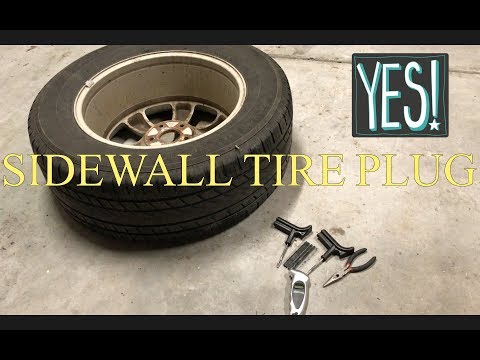
Fork contacts are not suitable for everyone, but only for terminals connected under a tightened screw, for example, as in the ABB S233R series machine.
In this article, as an example, consider a comb with the following characteristics (article 14883 according to the catalog of Schneider Electric):
KM-40). All this is placed in a special plastic case made of non-combustible material.
In other types, everything is similar, only two, three or four are used instead of one busbar, i.e. each pole has its own busbar.
In a three-pole comb, respectively, three copper bars placed in one housing.
Each bar is inserted into its own guide and there is insulation between them in the form of a plastic partition.
We figured out the design and classification. Now let's go directly to the connection.
Breakers are available with single and double wire clamps.
Most circuit breakers in the market have a single terminal. As an example, consider the already known to us, IEK BA47-29.
Everything is simple here. We select the necessary comb according to the parameters, insert it simultaneously under all the clamps of the machines and tighten the screws.
View from the back.
If you have 5 single-pole circuit breakers in a row, and the connecting bar is selected for 12 modules, then you need to measure the required distance and saw through the comb with a hacksaw or wire cutters (side cutters).
And don't forget the end caps. Or saw off the plastic with a margin so that there is a small distance to the shank along the edges.
Then you need to supply power to any of the machines, where it is more convenient for you. We loosen the clamp screw of the machine and insert an additional power wire there.
Some machines have double wire clamps.
For example, in a machine from the well-known company ABB, which I mentioned at the beginning of the article, you can insert a power wire (phase) into the first clamp, and a distribution bus with fork-shaped contacts into the second. It is very comfortable.
In my articles, I have said more than once that the outlet lines in the apartment must be protected using RCDs or difavtomatov. It will not be worse if they are also installed for lighting. Here is your choice.
If you listen to my advice, follow the rules and take care of the health of your family and friends, then in the apartment panel you will have an RCD installed on almost every line.
So, with the help of a two-pole comb (L + N), it is very convenient and quick to connect them together, rather than making so many jumpers, and be sure to observe the color coding, as in the photo below.
To begin with, let's list their advantages.
1. High-quality and reliable connection
using a connecting bus, the number of connections is reduced by 2 times. When using jumpers from wires, there will be two wires in one clamp of the protective device, and when using a comb, only one prong.
Some installers solve this issue with the following alternative - they make the connection of the machines not with separate jumpers, but from a solid wire without a break.
2. Bar section
The copper bar section is 16 mm2. Imagine how much time and effort it will take to make jumpers from wires of a similar section, as well as what quality of connection will be in the terminal of the machine when using two such wires.
Although, it is enough to carry out internal installation in the shield with a wire with a cross section equal to the cross section of the input cable.
3. Fast installation
I spoke about this at the very beginning of the article.
they are here too.
1. Replacing the circuit breaker
I think the most basic disadvantage is the case when we need to replace one circuit breaker. First, we need to de-energize the entire row of machines, then remove the entire comb, and then replace the machine, because otherwise it will not work here - you simply simply cannot remove the machine from the DIN rail.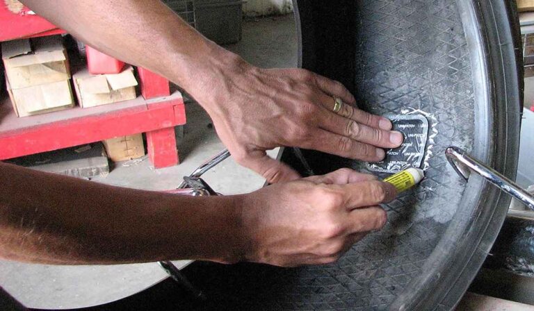
2. Adding additional machines to the shield
Imagine that one day you decide to add an additional machine to the shield, and the comb has already been measured to the existing row.
In this case, the new machine can only be powered by a jumper or it will be necessary to purchase a new comb.
The solution to the problem is to install in advance and power up backup circuit breakers with standard ratings - 10 (A) and 16 (A) in the panel.
Do you use combs when assembling shields? What advantages and disadvantages, in addition to the above, have you noticed? What nuances arose during installation?
If the article was useful to you, then share it with your friends:
Surely many of you know or have even seen how large automated objects are controlled, for example, a nuclear power plant or a plant with many technological lines: the main action often takes place in a large room, with a bunch of screens, light bulbs and consoles. This control complex is usually called the main control room - the main control panel for controlling the production facility.
Surely you were wondering how it all works in terms of hardware and software, and what data transfer protocols are used there. In this article, we will look at how various data gets to the main control room, how commands are given to the equipment, and what is generally needed to control a compressor station, a propane production unit, a car assembly line, or even a sewage pumping unit.
This set of words, which is not clear to the uninitiated, is used when it is necessary to describe the means of communication between control devices and subordinate equipment, for example, I / O modules or measuring devices.
By controller we mean PLC, i.e. programmable logic controllers (eng. PLC), or PKA, i.e. programmable automation controllers (eng.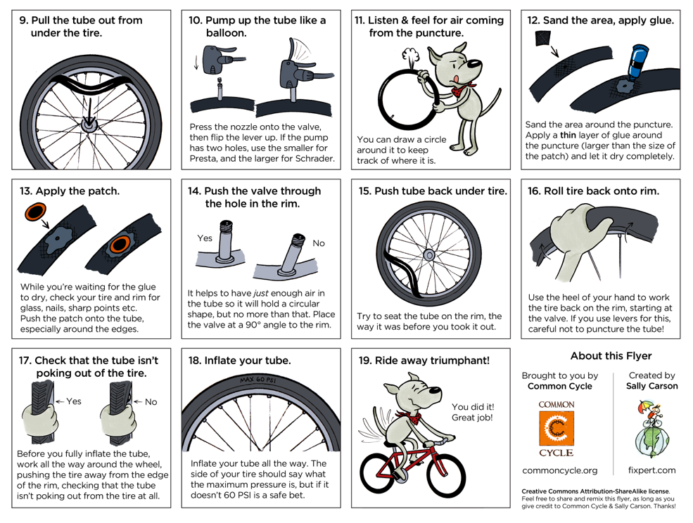 PAC). There are some differences between the PLC and PCA, however, they are not significant within the framework of this article, therefore, for simplicity, we will use the general term "controller".
In the Russian-speaking community of asush people, the communication channel between the controller and other devices is usually called the "field bus", because it is responsible for transmitting data that comes from the "field".
“Field” is a deep professional term that refers to the fact that some equipment (such as sensors or actuators) with which the controller interacts is somewhere far, far away, on the street, in the fields, under the cover of night. And it does not matter that the sensor can be located half a meter from the controller and measure, say, the temperature in the automation cabinet, it is still considered to be “in the field”. Most often, the signals from the sensors that come to the I / O modules still overcome distances from tens to hundreds of meters (and sometimes more), collecting information from remote sites or equipment. Actually, therefore, the exchange bus, through which the controller receives values from these same sensors, is usually called a field bus or, less often, a lower-level bus or an industrial bus.
It should be noted here that in Europe and the USA, only the devices located “in the field” are considered the field level, but not the data transmission medium. In Russian realities, the term "field bus" or "lower-level bus" is perhaps slightly vague and refers to the method of transferring data from I / O modules to the controller and vice versa.
General scheme of automation of an industrial facility
So, the electrical signal from the sensor travels a certain distance along cable lines (usually along a conventional copper cable with a certain number of cores), to which several sensors are connected. Then the signal enters the processing module (input-output module), where it is converted into a digital language understandable to the controller. Further, this signal goes directly to the controller via the field bus, where it is finally processed.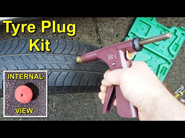 Based on such signals, the logic of the controller itself is built. There is also a reverse way: from the controller, the control command via the field bus goes to the output module, where it is converted from digital to analog and goes through cable lines to actuators and various devices (not shown in the diagram above).
The top level is everything that can be touched by an ordinary mortal operator who controls the process. In the simplest case, the top level is a set of light bulbs and buttons. Light bulbs signal to the operator about some ongoing events in the system, buttons serve to give commands to the controller. Such a system is often called a "garland" or "Christmas tree" because it looks very similar (as you can see from the photo at the beginning of the article).
If the operator is more fortunate, then as the top level he will get the operator panel - a kind of flat-panel computer that somehow receives data for display from the controller and displays them on the screen. Such a panel is usually mounted on the automation cabinet itself, so you usually have to interact with it while standing, which causes inconvenience, plus the quality and size of the image - if it is a small-format panel - leaves much to be desired.
And, finally, an attraction of unprecedented generosity - a workstation (or even several duplicates), which is an ordinary personal computer.
For visual display of information on workstations and flat-panel computers, specialized software is used - SCADA systems. In human language, SCADA is translated as a supervisory control and data acquisition system. It includes many components, such as a human-machine interface that visualizes technological processes, a process control system, a parameter archiving system and event logging, an alarm management system, etc. All this gives the operator a complete picture of the processes taking place in the production, as well as the ability to manage them and quickly respond to deviations from the technological process.
Top-level equipment must interact in some way with the controller (otherwise why is it needed?). For such communication, upper-layer protocols and some kind of transmission technology, such as Ethernet or UART, are used. In the case of the Christmas tree, of course, such refinements are not needed, the bulbs are lit using ordinary physical lines, there are no sophisticated interfaces and protocols there.
In general, this upper level is less interesting than the field bus, since this upper level may not exist at all (there is nothing for the operator to watch from the series, the controller will figure out what to do and how).
Few people know, but on the seventh day of the creation of the world, God did not rest, but created Modbus. Along with the HART protocol, Modbus is perhaps the oldest industrial communication protocol, it appeared as early as 1979.
The serial interface was originally used as a transmission medium, then Modbus was implemented over TCP / IP. This is a synchronous master-slave (master-slave) protocol that uses the request-response principle. The protocol is quite heavy and slow, the exchange rate depends on the characteristics of the receiver and transmitter, but usually the score is almost hundreds of milliseconds, especially when implemented via a serial interface.
Moreover, the Modbus data transfer register is 16-bit, which immediately imposes restrictions on the transfer of real and double types. They are transmitted either in parts or with loss of accuracy. Although Modbus is still widely used in cases where a high exchange rate is not needed and the loss of transmitted data is not critical. Many manufacturers of various devices like to extend the Modbus protocol in their own unique and very original way, adding non-standard features. Therefore, this protocol has many mutations and deviations from the norm, but still successfully lives in the modern world.
The HART protocol has also been around since the 1980s, it is an industrial communication protocol over a two-wire current loop that directly connects 4-20 mA transmitters and other HART-enabled devices.
Special devices, so-called HART modems, are used for switching HART lines. There are also converters that at the output provide the user with, say, the Modbus protocol.
HART is noteworthy, perhaps, in that in addition to the analog signals of the 4-20 mA sensors, the digital signal of the protocol itself is also transmitted in the circuit, this allows you to connect the digital and analog parts in one cable line. Modern HART modems can be connected to the controller's USB port, connected via Bluetooth, or in the old way via a serial port. A decade ago, by analogy with Wi-Fi, the WirelessHART wireless standard appeared, operating in the ISM band.
The Modbus and HART protocols have been replaced by non-industrial buses such as ISA (MicroPC, PC/104) or PCI/PCIe (CompactPCI, CompactPCI Serial, StacPC), as well as VME.
The era of calculators has come, having at their disposal a universal data transfer bus, where you can connect various boards (modules) to process a certain unified signal. As a rule, in this case, the processor module (computer) is inserted into the so-called frame, which provides bus interaction with other devices. The frame, or, as true automators like to call it, the “crate”, is supplemented with the necessary I / O boards: analog, discrete, interface, etc., or all this is glued together in the form of a sandwich without a frame - one board above the other. After that, this variety on the bus (ISA, PCI, etc.) communicates with the processor module, which thus receives information from sensors and implements some kind of logic.
Controller and I/O modules in a PXI cage on a PCI bus. Source: National Instruments Corporation
Everything would be fine with these ISA, PCI (e) and VME buses, especially for those times: the exchange rate does not upset, and the system components are located in a single frame, compact and convenient, hot-swappable input boards - output may not be, but still do not really want to.
But there is a fly in the ointment, and not just one. It is rather difficult to build a distributed system in such a configuration, the exchange bus is local, you need to come up with something to exchange data with other slave or peer nodes, the same Modbus over TCP / IP or some other protocol, in general, there are not enough amenities. Well, the second thing is not very pleasant: I / O boards usually wait for some unified signal for input, and they do not have galvanic isolation with field equipment, so you need to fence a garden of various conversion modules and intermediate circuitry, which greatly complicates the element base.
Intermediate modules for signal conversion with galvanic isolation. Source: DataForth Corporation
"What About the Fieldbus Communication Protocol?" - you ask. But nothing. It does not exist in this implementation. Through cable lines, the signal goes from the sensors to the signal converters, the converters output voltage to a discrete or analog I/O board, and the data from the board is already read through the I/O ports, by means of the OS. And no specialized protocols.
What now? To date, the classical ideology of building automated systems has changed a bit. Many factors played a role, from the fact that it should also be convenient to automate, and ending with the trend towards distributed automated systems with nodes remote from each other.
Perhaps, we can say that today there are two main concepts for building automation systems: localized and distributed automated systems.
In the case of localized systems, where data collection and control is centralized in one specific place, the concept of a certain set of I / O modules interconnected by a common fast bus, including a controller with its own exchange protocol, is in demand. In this case, as a rule, I / O modules include both a signal converter and galvanic isolation (although, of course, not always). That is, it is enough for the end user to understand what types of sensors and mechanisms will be present in the automated system, count the number of required I / O modules for different types of signals and connect them into one common line with the controller. In this case, as a rule, each manufacturer uses its favorite exchange protocol between I / O modules and the controller, and there can be a lot of options.
In the case of distributed systems, everything that has been said about localized systems is true, except for this, it is important that individual components, for example, a set of I / O modules plus an information collection and transmission device - not a very smart controller that is somewhere in booth in the field, next to the crane that shuts off the oil, could interact with the same nodes and with the main controller at a great distance with an effective exchange rate.
How do developers choose a protocol for their project? All modern exchange protocols provide a fairly high speed, so often the choice of a particular manufacturer is not determined by the exchange rate on this same industrial bus. The implementation of the protocol itself is not so important, because, from the point of view of the system developer, it will still be a black box that provides some internal structure for the exchange and is not designed for outside interference. Most often, attention is paid to practical characteristics: the performance of the calculator, the convenience of applying the manufacturer's concept to the task, the availability of the required types of input-output modules, the possibility of hot-swapping modules without breaking the bus, etc.
Popular equipment vendors offer their own implementations of industrial protocols: for example, the well-known company Siemens develops its series of Profinet and Profibus protocols, B&R develops the Powerlink protocol, Rockwell Automation develops the EtherNet/IP protocol. The domestic solution in this list of examples: the version of the FBUS protocol from the Russian company Fastwel.
There are also more universal solutions that are not tied to a specific manufacturer, such as EtherCAT and CAN. We will explore these protocols in detail later in this article and see which are best suited for specific applications: automotive, aerospace, electronics, positioning systems, and robotics.