Trying to see how to test a cdi box with a multimeter?
Super, you are in the right place!
In this ToolsGaloreHQ.com blog, we will show you:
Check out the table below before continuing with the rest of the guide on how to test cdi box with a multimeter.
What you need to know about how to test CDI box with a multimeterThe capacitor discharge ignition (CDI) as you know is that black box on your motorcycle that basically functions as the brain of the ignition and motor unit.
This unit is typically found underneath the seat.
It is so common in motorcycles now a days, and has all but replaced the old mechanical trigger mechanisms of the past (before 1980’s).
Before we get into the various steps on how to test your cdi box using a multimeter.
Let's understand a few critical components of the CDI to ensure that your testing is not just theoretical but is backed up by a firm and solid understanding of the underlying electronics involved.
Internal Workings of your CDI
The CDI has the components as shown in the image below
Source: usman032.com
The alternator (exciter) coil is typically powered with an AC voltage ranging anywhere up to 400 Vac.
This passes through a forward biased diode and produces a DC voltage which is inturn fed to the micro-capacitor and the silicon controlled rectifier (SCR).
The SCR is further controlled by a pulse coil which dictates it’s open and close position.
Read More:>> Find the Best Multimeter under $50
When the SCR is closed. This creates a short circuit causing current to flow from the charged capacitor in the direction as shown below.
This charges the ignition coil before releasing the energy to the spark plug, and hence providing energy to the engine.
There are various symptoms that can be derived from a defective cdi. Of which you will be able to use a multimeter to test. They are listed here below.
Misfiring engine
There are many reasons as to why an engine could misfire.
Getting the help of a professional mechanic would usually be your best bet. However a worn out ignition coil found within the cdi is a very common issue with misfiring engines.
Dead Cylinder
This occurs when one or more of the cylinders fails to fire properly.
Often what will happen is that the CDI could have a defective blocking/forward diode, creating fuzzy voltage signals which inturn confuse the spark plug’s firing mechanism.
Backfiring
This tends to happen at higher RPMS above 3000. It can be an issue on the stator, but it has been shown that a bad cdi can contribute to backfiring.
SafetyPlease ensure that whenever you are working with cdi parts or motorcycle mechanics you ensure that you use the typical Personal protective equipment.
The minimum that should be use cut resistant and water proof mechanical gloves, protective and protective eyewear.
I can tell you from experience working with electrical equipment that safety and the dangers that come from not protecting yourself adequately can be very dangerous.
CDI’s are active components that have capacitance inside although this is usually minimal (i.e. micro farads). You should not take your safety lightly.
Step 1 -Remove CDI box from motorbike
The CDI is usually connected with insulated leads and pin connectors. Disconnecting this from the motorcycle should not be too difficult.
Make sure that you do not work on the cdi immediately. Let it sit for at least 30 minutes to 1 hour to allow the internal capacitance to discharge.
Also during this step, it is important to run a visual inspection of your CDI. Typically damaged CDI’s have some form of mechanical deformation in the form of heat or damaged insulation from the casing.
Read More:>> Testing Purge Valve using a Multimeter
Step 2 – Testing CDI (Cold Test)
Here is the image we used above again as a reminder of the internal circuitry
This method requires us to test the cdi for continuity.
So what you would do is set your multimeter to continuity mode. First take the leads of the multimeter and connect them together.
If you are using a digital multimeter then you should hear a beeping sound.
Measure for continuity between all the ground and the various other points.
If your cdi is working well, you should not hear any sounds. If you do however hear any beeping sound as you are testing, then you cdi is faulty.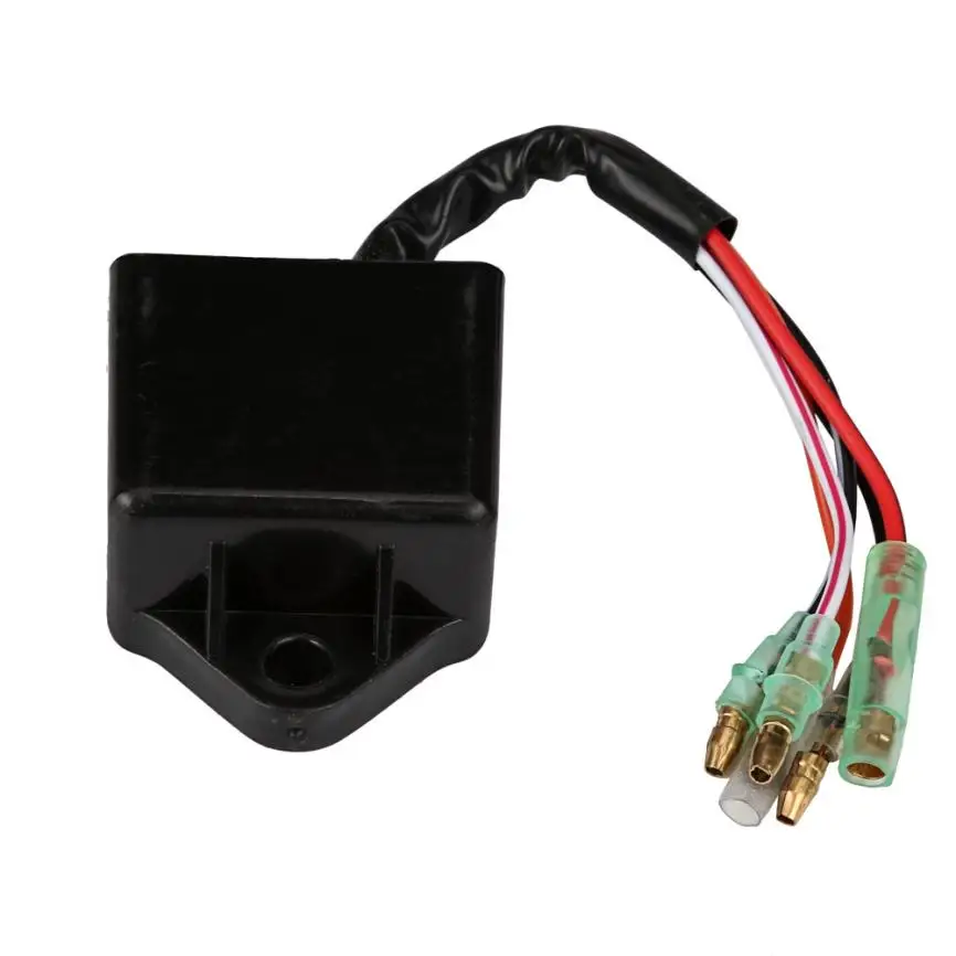
All is not lost at this stage, the cdi can still be rectified if you are able to fix the defective component.
Usually on a cdi when you have continuity between ground and any of the other terminal points , it either means that the diode, scr or the capacitor has failed.
Step 3 – Testing CDI (Hot Test)
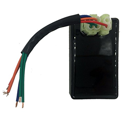
There is an alternative method to testing the cdi box whilst it is still connected to the stator of the motorbike. Generally cdi boxes have a blue and white wire than comes from the stator to the cdi box itself.
When testing for continuity on the multimeter, it is important to test via the stator end rather than the cdi end.
This is because it is notoriously difficult to get any test lead connection through to a connected cdi box.
The voltage, continuity and resistance is generally the same as on the stator end.
There are a couple of things that you would want to test. Namely:
 Whilst in general the white wire to ground should provide you with a resistance of between 360 to 490 ohms.
This will provide you a genera hot health status check of your cdi box. If the resistance values on your multimeter reading go outside of this range. It is worth checking it with a mechanic.
Read More:>>> Learn more about clamp meters vs multimeters
Final thoughts on how to test CDI box with a multimeterHaving a motorbike that does not fire correctly or produces cracky idling can be a pain to diagnose.
One thing that is often overlooked in checking the cdi for it’s health and functionality with a multimeter.
I hope this guide has provided you with additional insights as to how to test your cdi box with a multimeter.
In your automotive vehicle, the CDI is one of the most important components. What is a CDI box and what does a CDI box do?
In a motorcycle, a CDI is a black box underneath the seat that functions as the heart of your ignition system.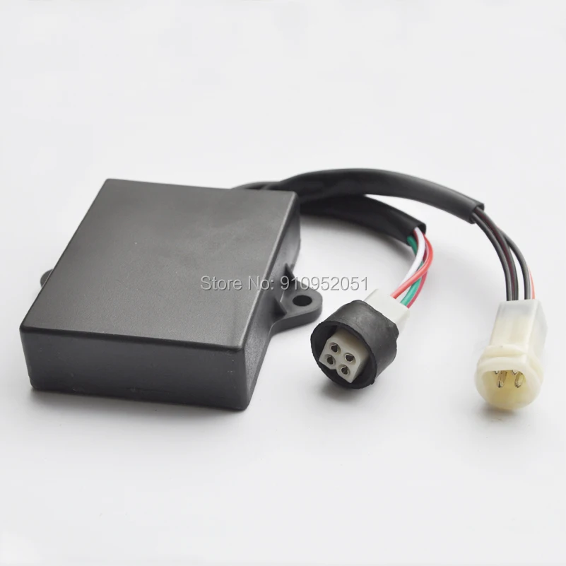 It is an electronic component that replaces the pre-1980 mechanical ignition processes and one that your bike can’t work without.
Nonetheless, just like every other component in your bike, issues arise with it and making a diagnosis may be tough.
This article presents you with all you need to know about a CDI box. Let’s get right in.
Here is the system of components in a CDI:
Source: Usman032As the key is turned, the rotating magnet induces a voltage of up to 400Vac into the Excitor coil. When this coil becomes positive, the charge is directed to the forward biased diode till the capacitor gets fully charged ( usually after 3 to 4 magnet rotations).
Once the capacitor is charged, the pulse rotor sends a trigger to the SCR which, in turn, initiates a conduction process that discharges the capacitor immediately. This sudden discharge produces a high spike of voltage in the ignition coil.
High current on both contacts of the spark plug is created and this provides power to the engine.
The ignition stop switch grounds all excess voltage.
Of course, before getting into your CDI, you want to be sure that there are problems with it. Here are some of the symptoms your bike may be exhibiting that point you to issues with a CDI.
These symptoms represent problems with particular components of the CDI box. For instance, a misfiring engine may be caused by either worn out spark plugs or a worn out ignition coil. A dead cylinder may also be caused by a bad ignition coil or a bad diode.
Identifying exactly where the problem lies helps you to easily make fixes or replacements and get your ignition systems up and running again.
How do you identify these problems? A multimeter proves useful throughout the whole process and here is how you test your CDI box with it.
All you need is your;
Before moving forward, you also need to take safety measures and protect yourself. These measures include wearing cut and water resistant gloves as well as eye safety equipment.
To test your CDI box, you disconnect it from your bike, use the positive and negative leads of your multimeter to check for continuity, and listen for a beeping sound which signals that it is faulty.
There is a whole lot more to this seemingly straightforward process and here is further details on it.
To test your CDI, you engage in both cold testing and hot testing procedures. Cold testing is when you run diagnosis on the CDI box with it disconnected from the stator, while hot testing has it still connected to the stator.
Do the following.
This is for cold testing procedures. The CDI Box is typically located underneath the seat of your bike. As you check, you should see a blue and white wire connecting the stator and black CDI box together through lead and pin connectors.
Once disconnected, you avoid working on your CDI with any equipment for about 30 minutes to an hour. As the internal capacitor discharges during this waiting process, you carry out a visual inspection on your CDI.
Visual inspections may allow you to quickly identify physical deformations on the CDI.
Cold testing involves inspecting the continuity of your CDI box components. What you do is set your multimeter to continuity mode and test the continuity between the ground point and other terminal points within the CDI.
If a problem exists, your multimeter gives off a beeping sound. You know the exact component that has issues and a fix to this component may be the solution.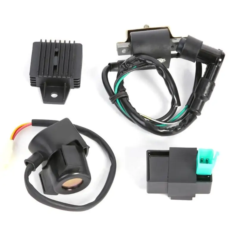
Continuity issues within a CDI are usually caused by problems with the SCR, Diode, or internal capacitor. If these cold steps prove a little difficult to follow, this video from youtube may help you out.
If you don’t want to disconnect the CDI from the bike, you could run a hot test. Tests are made from the stator end of the blue and white wire that connects it to the CDI.
To do this, you set your multimeter to a 2k ohms resistance and measure resistance between these two points; the blue wire to the white wire and the white wire to ground.
For the blue wire to the white wire, you check for a resistance reading between 77 and 85. With the white wire to ground, you use your multimeter to check for a resistance between 360 to 490 ohms. If any of these don’t match, your stator could be faulty and a professional mechanic could prove useful.
If they match, however, then your CDI is a likely culprit.
You know a CDI box is bad when your bike misfires, has dead cylinders, unusual tach behavior, runs roughly, experiences ignition problems, or its engine stalls.
To bypass your CDI box, you clear your bench, remove the box, check resistance specifications, measure the primary and secondary oil resistance, and compare readings.
A bad CDI box may not cause a spark at all. However, your bike shows symptoms like ignition problems, dead cylinders, and engine stalling.
A bike will not start without a CDI box as it is the component that controls the ignition system.
No. CDI boxes are not universal because ignition systems vary across different vehicle models. They come as either AC or DC.
To test the CDI box for an ATV, you use a multimeter to inspect the fuses, ignition switch, ignition trigger coil, electronic module, and check for loose wires.
The CDI box is an important component of your vehicle’s ignition system and you should take good care of it. No matter how clear these steps may be, hiring the expertise of a professional mechanic seems a better option.
Almost all carburetor engines of ATVs and motorcycles are traditionally equipped with a CDI (Capacitor Discharge Ignition) ignition system. In this system, energy is stored in a capacitor and at the right moment it is discharged through the primary winding of the ignition coil, which is a step-up transformer. A high voltage is induced in the secondary winding, which breaks through the gap between the electrodes of the spark plug, forming an electric arc that ignites the mixture of gasoline and air.
To synchronize the ignition operation, an induction crankshaft position sensor is used - DPK, which is a coil wound on a permanent magnet core:
The mark is the tide on the iron housing of the generator rotor (popularly called the flywheel): sensor core , it changes the magnetic flux through the coil , thereby inducing a voltage across the coil 's terminals . The waveform is as follows:
i.e. two pulses of different polarity. On almost all engines, the polarity of switching on the sensor is such that the first is a positive pulse corresponding to the beginning of the tide, and the second negative - the end of the tide. For normal engine operation, ignition must occur a little earlier than top dead center - TDC, so that the maximum pressure of the combustion products reaches just at TDC. This “slightly earlier” is commonly called the Ignition Advance Angle - UOZ and is measured in degrees, which are left to turn the crankshaft to TDC. When starting the engine, the UOZ should be minimal, and with an increase in speed, it should increase. As mentioned above, the WPC produces two synchronization pulses - the beginning of the tide and the end of the tide. In simple (not microprocessor) CDI systems, the end of the tide corresponds to the pre-set UOZ - this signal ignites when the engine is started and at idle. The onset of the tide corresponds to the SPD at high speeds. Most often in such systems, the end of the tide is set to 10-15 degrees ahead, and the “length” of the tide is from 20 to 30 degrees. At the same time, advanced CDI units smoothly change the moment of sparking from the “end of the tide” to the “beginning of the tide” in the range from 2000 rpm to 4000 rpm, while the cheap ones simply jump to the beginning of the tide with increasing speed. In CDI microprocessor systems, the length of the tide is much longer - from 40 to 70 degrees, while its end, as before, corresponds to the preset UOZ, and the beginning is the starting point for the microprocessor, which, depending on the speed, sets the desired UOZ.
In different engines, the “length” of the tide is different, therefore CDI blocks, even with the same connectors, are most often not interchangeable!
It should also be added that high voltage is needed to power the CDI units, because. the time of energy accumulation in the capacitor is limited; its capacity is taken small and it is charged with a high voltage - several hundred volts. For this, in simple systems, the generator has an additional high-voltage winding. The power of this winding is small, so the spark in such systems at engine start is weak, which makes winter operation difficult. To avoid this problem, so-called DC-CDIs are used, in which the capacitor is charged from a battery-powered boost converter. In such systems, the power of the spark does not depend on the speed and starting the engine in cold weather is much easier.
Now for the disadvantages of CDI ignition. The most important disadvantage, which cannot be eliminated for little money, is a very “weak” “short” spark. It is impossible to build a powerful CDI system without significant material costs.
For example, CDI for domestically developed car engines cost more than a thousand dollars, and imported ones, which are installed on racing cars with high-speed engines, can cost more than one thousand.
The larger the volume of the cylinder in the engine, the stronger the effect of the lack of spark energy.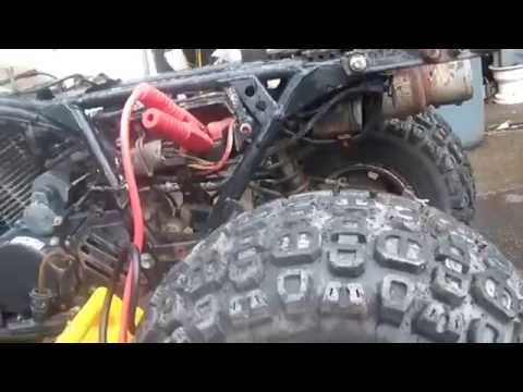 This is expressed in incomplete combustion of fuel, loss of power, very high fuel consumption. When CDI first appeared, it was put on mopeds, motorcycles, most often the engine size of which was 50 cubes. Such a small amount of air-fuel mixture was easily burned out by a weak CDI spark. With the increase in cubic capacity, it became clear that something needed to be changed and DC-CDI appeared. But the cubic capacity continued to grow, and with it the amount of gasoline that literally flew into the pipe grew. They even came up with systems that burn gasoline in the exhaust pipe! :about) I don’t understand what the manufacturers of motorcycles were thinking all this time, because at the same time, a different ignition system was used on cars for a long time, with the accumulation of energy in an inductor, which made it possible to get hundreds of times more spark power for the same money and solve everything ignition problems. Of course, CDI is no longer installed on the injection engines of modern motorcycles.
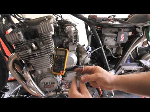 But this is a drop in the ocean! Today the picture is that 90 percent of motorcycles and ATVs continue to eat gasoline and spit it out into the atmosphere.
It would seem that everything is very simple - it is necessary to change the ignition for all to a more perfect one, but there are a few BUT! If it's CDI, then it turns out very expensive. If it is IDI, as in injection systems, then for its operation it is necessary to change the generator rotor, which is even more expensive. (for correct control of the coil operating modes in the IDI system, one mark on the flywheel is not enough, several dozen short marks are used - in fact, a gear wheel with synchronization by a missed tooth) All this is true if we solve the problem head-on. But if you think a little, apply a powerful microprocessor and show ingenuity, it turns out that not everything is so bad!
BACK!
ATTENTION!!! DO NOT SWITCH ON THE IGNITION WITHOUT THE HIGH WIRE, THE PLUG, OR IF THE PLUG IS NOT TWISTED INTO ITS PLACE OR IS NOT RELIABLELY EARTHED TO THE ENGINE BODY!!!
A SCRETTER WILL COME TO THE COIL WITH A PROBABILITY OF MORE THAN 50 PERCENT!!!
IN THIS COIL, A BREAKDOWN OCCURRED INSIDE THE COIL AND A INTERTURN FAULT MAY APPEAR!!! THE PRESENCE OF THE INTERTURN CLOSURE OFTEN DOES NOT INTERFERE TO WORK AND THE SPARK IS PRESENT, BUT NOT FOR LONG - AT THE END OF THE END THE COIL DIES AT ALL.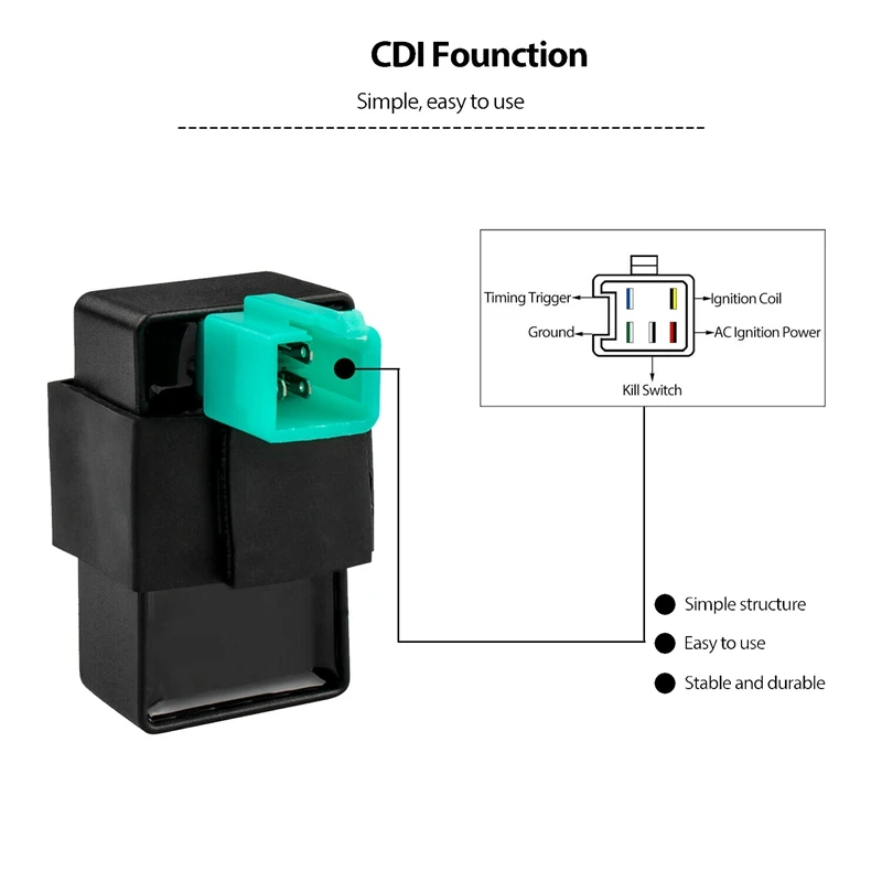
To connect the ignition control unit (BUZ) to the ATV's on-board network (only connector 1 is used), disconnect the standard CDI unit from its connector (on some models, the standard unit is not disconnected, see clarifications in the descriptions) or disconnect the DPK connector, disconnect the BB wire of the standard ignition coil from the spark plug, to the “signal” wire (most often it is a blue or white-blue wire) of the DPK, connect the input of the BUZ (blue wire) ,)
the DPK wire (let's call it "-" DPK) (most often green) is connected to ground (sometimes it is connected to ground only in the CDI unit, sometimes directly in the generator itself, if not, we connect it to the "-" battery, the yellow wire of the BUZ to + Battery after the ignition switch (most often it is a black wire), white wire to the “-” terminal of the ignition coil, Terminal “+” of the ignition coil through a 15 amp fuse to + battery, BB wire to the coil and spark plug.
Everything, you can start. As wound up, you should adjust the speed of the twentieth.
To return to the standard ignition system: disconnect the connector 1 BUZ, the standard CDI unit back into its place, the BB wire from the standard coil to the spark plug.
Connector number 2 is optional, add. functions are activated by shorting the desired wire to MASS !!! If they are not needed, insert a chip into the connector anyway so that WATER does not get in !!! it is necessary !!!
There are a few things to pay attention to when installing and starting the system. Here is a list of what caused the ignition to work poorly on different quadrics: