Have you ever asked yourself this question: "How do I check the tire pressure without a gauge?"
If yes, then look no further!
This article will reveal seven practical ways of checking the pressure of your tires when you do not have a gauge at hand.
Also, you will know how often you should check your tire pressure, when to tell if your tires are underinflated, and many more.
Why Do You Need To Check Tire Pressure?To Prevent AccidentsLow tire pressure causes the rapid loss of tire tread depth in less time than usual. This is because the tires endure more weight and force than when they are correctly inflated. Underinflated tires may also cause poor handling of the car.
Overinflated tires can lead to a blowout during a ride. Regular pressure checks prevent accidents caused by blowouts and poor maneuverability of the car.
To Improve Fuel EconomyTire pressure checks enhance the fuel economy of your car. Low-pressure tires require more propelling power to get going. This indicates that your vehicle will burn extra fuel to supply the energy needed to move your underinflated tires. So you may notice that you're purchasing gas more often than you should.
Underinflated tires carry the weight of your vehicle more than the other adequately inflated tires. If the tire pressure is too low, too much of that tire's surface area touches the road, which increases friction. Increased traction may cause the tire to overheat, which can lead to premature wear. Regular checks ensure the uniformity of tire wear.
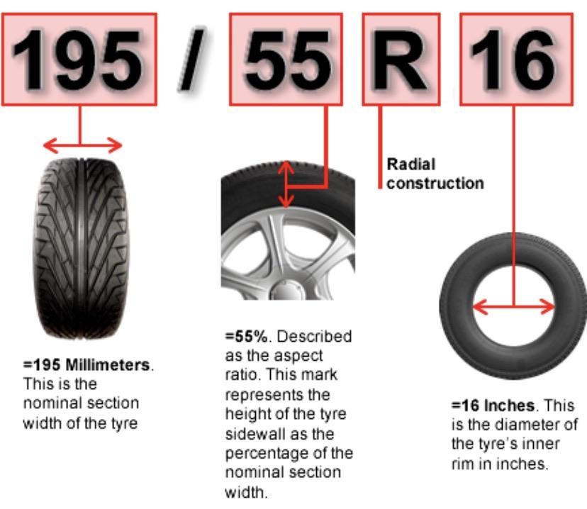
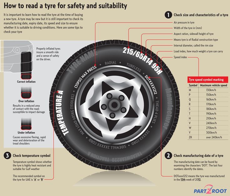
How To Check Tire Pressure Without GaugePound-force Per Square Inch Check (PSI Check)The pound-force/square inch is the unit used to measure air pressure in your tire. It lets you know how much inflation pressure your tire can withstand. The driver's manual usually provides this information.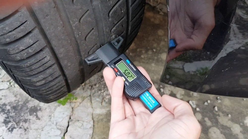 You may also notice it on the driver's side of the doors.
The number usually suggests the lowest pound-force per square inch at which the tire must be inflated. But you may vary it as you think necessary.
The more the vehicle can carry, the more pressure is needed for proper functioning. The suggested PSI for small cars like minivans and sedans ranges between 27 and 32. But those tires can reach 40 if necessity demands so. SUVs and trucks have a PSI of about 45 and more because their tires need more inflation pressure to carry the vehicle's weight properly.
Take note that some models of pickup trucks have different PSI for the front and rear tires. Check your manual to be sure.
Thumb CheckYou can use your thumb to check the pressure of your tire. All you have to do is push your thumb down on the tire to feel the pressure. Underinflated tires will be soft. You will find your tires to be extremely stiff if they are overinflated. The tire pressure is proper if your tire is not too soft or too stiff as mentioned above.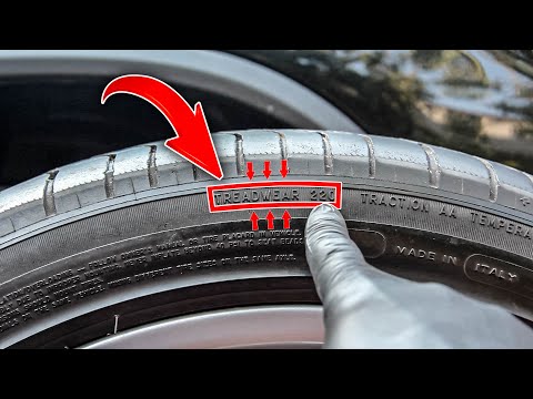
This method is based on checking the level of deformity of the tire once you mount weight on your tires. What you do is to put weight on the tires, and then notice the level of deformity of the tire. Tires with low pressure get deformed by 10% - 15% change. If you see that much difference, you need to inflate your tires a little more. As you add pressure, check gradually to see that the tires do not become extremely stiff.
Trail Comparison CheckFor this method, you need a pavement or a road with a flat surface. You need to apply ink or some other marking substance to your tires. After that, make marks on the road by driving the car slightly. After the drive, pay attention to the trail that your tires made. A comparison of the trail will reveal some differences. Low-pressure tires tend to leave a streak when compared with others.
Inflate the underinflated tires a little more and repeat the test until the moderate pressure is reached.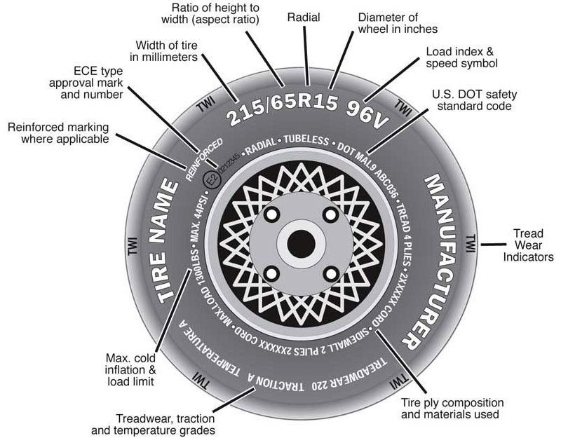
This test works with cargo. Load some cargo on the car and notice how the tires might get weighed down.
Cargo will logically weigh down any low-pressure tire of your vehicle. If you notice that one side of the car bears the cargo load more than the other, it means you have low-pressure tires that need more air pressure. Find the underinflated tires and add more air to even the distribution of the weight.
But ensure you check and return the tires’ Pound-force Per Square Inch (PSI) to normal by adding more air pressure after you remove the cargo.
Hand Pressure CheckTo check your tire pressure with your hand, push your palm down on the tire to feel the pressure. Low-pressure tires are usually soft and cushiony, while overinflated tires are incredibly stiff.
If it feels soft, inflate the tire with more air. Check pressure with your palm gradually as you add air to it. If the air pressure is too much, press the stem on your tire’s air nozzle until a slight push over the tire is possible.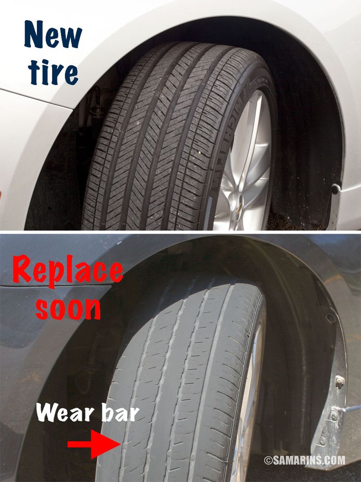
To check your tire pressure with this method, you must first park your car on a plane surface. After parking it, check the tires of your vehicle from both sides. What you are looking out for is a bulge; a round swelling from any side of the tire.
A bulge of more than ten millimeters on both sides shows that your tire pressure is low. You may have to pump the tires before taking the vehicle out. Inflate the tires until it is hard but not extremely hard.
How Often Should You Check Your Tire Pressure?Car manufacturers recommend that you check at least once a month. But safety and other reasons may make you have to examine your tire pressure more frequently.
Ideally, you should visually observe your tire pressure every time you approach your car.
Try to regularly check your tire pressure when you visit the gas station.
If you hit a curb or run over a sharp object, you may also have to check your tire pressure.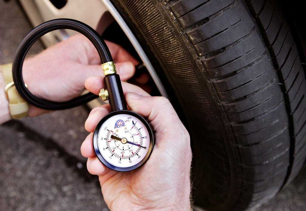
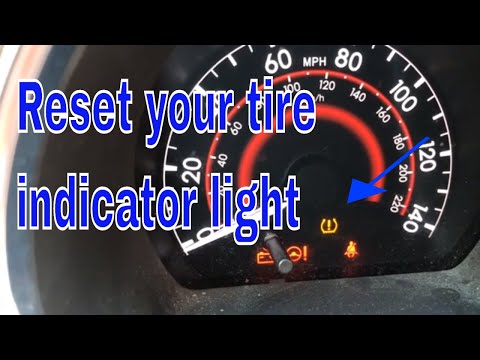
Some recent vehicle models have a warning light in the dash to alert you. The warning light is a component of the Tire Pressure Monitoring System of your vehicle. The light comes on to warn you that your tires could be underinflated.
If your car does not have a caution light for low tire pressure, a regular check will help you know if your tire pressure is too low.
Difficulty in the car's maneuverability or losing speed is also a sign that the tire pressure may be low.
Is It Safe To Drive With Low Tire Pressure?It, it isn’t. It is dangerous to drive with low tire pressure, especially at high speeds. You could lose control of your vehicle. More seriously, driving with low tire pressure could also cause a blowout or an accident.
ConclusionDriving with the correct tire pressure is very important because you can protect your safety and the safety of other road users. It also saves you money because your tires wear evenly, and your fuel economy is optimal.
If you do not have a gauge with you, the reliable steps above-mentioned work just fine.
Guest Author: Tim Miller
I’m Tim Miller, an auto mechanic and the Editor-in-chief at obdadvisor.com. I love writing to share my experiences and expertise. Many articles about car repair, car parts and tools reviews can be found on my website. Get connected with me on Facebook, Twitter and Linkedin.
Tire-pressure warning lights are typically located in the gauge cluster of an automobile's dashboard. Warning lights are usually yellow or amber and resemble a cross section of a tire with an exclamation point and/or the letters "TPMS." (You can see one in the photo above, just to the left of the speedometer.) This small telltale illuminates to inform you of low air pressure in one or more tires when that issue is detected by the vehicle's tire-pressure monitoring system (TPMS).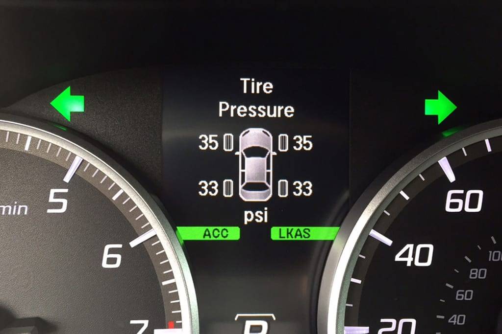
In general, the light will come on when the air pressure in one or more tires is outside the recommended range. Since the tires' optimal performance and safety benefits are realized within a specific range of air pressure, measured in pounds per square inch (psi), the warning light may illuminate when pressure has dropped as little as 10 percent below the recommendation—long before low pressure is visible to the eye.
Some of the more sophisticated tire-pressure monitoring systems will tell drivers which tire is out of range or display real-time air pressure in each tire—including spare tires, in some cases.
If your tire-pressure warning light comes on, don't ignore it; you could be getting a flat.
Low pressure could result from a leak or simply from the tendency of a tire to lose about a pound of air pressure every month, as well as a pound for every 10-degree drop in temperature. So if your tires are inflated properly in the summer, they could be low enough by the winter months to prompt the tire-pressure warning. Similarly, if a tire-pressure light illuminates on a cool morning, it could shut off if the ambient temperature climbs high enough to bring the tires back to an acceptable pressure. Tires warm up as you drive, raising their internal pressure by about 3 psi, which is another reason the TPMS warning might be on first thing in the morning and off later in the day.
Getty Images
Either way, whenever a tire-pressure warning light turns on, it's time to check your tires with a tire-pressure gauge, which costs as little as $5. A monthly pressure check of all your tires can help you keep them at the optimal level of inflation and will enable you to identify slow leaks early—possibly even before the pressure drops low enough for the warning light to come on.
If your TPMS warning light does come on, find the closest gas or service station and check the pressure of all four tires (plus the spare, if applicable), adding air to any that fall below the range listed on a sticker inside the driver's door. Once the tires are properly inflated, the light may go off after you've driven a few miles. If the light doesn't automatically turn off after about 10 miles, the TPMS may need to be reset, as directed in the vehicle's owner's manual. If the light comes on and all your tires are within the acceptable range, there's a chance that you have a malfunctioning tire-pressure monitoring sensor that needs to be replaced. No matter what the issue turns out to be, pay attention if the tire-pressure light turns on; you'll be safer for it, and you might also avoid damaging your tires.
Tire Rack
Buy Now
Tire Rack
Buy Now
Tire Rack
Buy Now
Tire Rack
Buy Now
Car and driverCar and driver Lettermark logoSteve Siler
Steve Siler started a car column at his college newspaper in 1995 and has been writing about cars ever since, with his musings and photographs having appeared in scores of different print and online publications.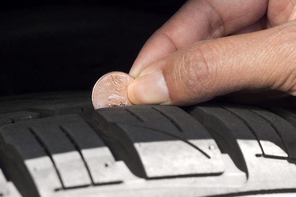 Born in Los Angeles, California, where he still lives and works when he's not on a media drive program or covering a car show, Siler brings a West Coast perspective to his coverage and has been a contributor to Car and Driver since 2006.
In order to streamline the work of all controllers that make driving easier and increase control of driving, a CAN-bus is used. You can connect such a device to the car alarm with your own hands.
[ Hide ]
CAN bus is a network of controllers. The device is used to combine all the control modules of the car into one working network with a common wire. This device consists of one pair of cables called CAN. Information transmitted through channels from one module to another is sent in an encoded form.
Scheme for connecting devices to the CAN bus in Mercedes
What functions can the CAN bus perform:
This system operates in several modes:
Channel Vialon Drying in his video told about the CAN bus and what you need to know about its operation.
What are the advantages of CAN bus:
 The owner of the machine does not have to spend money on installation, since you can do this task yourself.
 What disadvantages are typical for the device:
 This causes an increase in response time.
 The most popular tire type is the one designed by Robert Bosch. The device can function sequentially, that is, the signal is transmitted after the signal. Such devices are called Serial BUS. On sale you can also find parallel buses Parallel BUS. In them, data transmission is carried out through several communication channels.
You can learn about the varieties, principle of operation, as well as the capabilities of the CAN bus from the video shot by the DIYorDIE channel.
Taking into account different types of identifiers, several types of devices can be distinguished:
 These nodes do not indicate pulse errors of the 29-bit node.
 Please note that these types of devices are not used in modern machines. This is due to the fact that the operation of the system must be consistent and logical. And in this case, it can operate at several pulse rates - at 125 or 250 kbps. A lower speed is used to control accessories such as interior lights, power windows, windscreen wipers, etc. A high speed is needed to ensure the operation of the transmission, powertrain, ABS system, etc.
Let's consider what functions exist for various devices.
When the device is connected, a fast data transmission channel is provided, over which information is distributed at a speed of 500 kbps.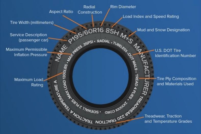 The main purpose of the bus is to synchronize the operation of the control module, for example, the gearbox and the motor.
The data rate on this channel is lower and is 100 kbps. The function of such a bus is to connect all devices belonging to this class.
Baud rate is the same as for Comfort devices. The main task of the bus is to provide communication between serving nodes, for example, a mobile device and a navigation system.
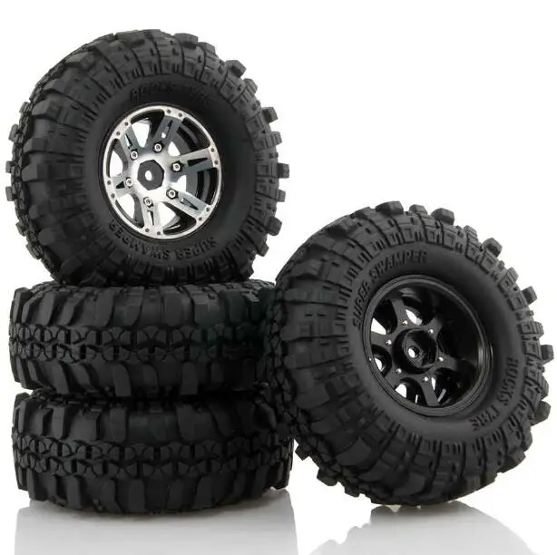
Tires from different manufacturers are shown in the photo.
1. Device for automobile internal combustion engines 2. Interface analyzer
In a modern car, the digital bus is constantly used. It works simultaneously with several systems, and information is constantly transmitted through its communication channels. Over time, the device may experience problems. As a result, the data analyzer will not function properly. If problems are found, the car owner must find the cause.
For what reasons there are malfunctions:
When looking for causes, keep in mind that the malfunction may lie in the incorrect operation of auxiliary devices installed additionally. For example, the reason may be the malfunctioning of the anti-theft system, controllers and devices.
You can learn about the repair of the dashboard CAN bus in a Ford Focus 2 car from a video shot by a Brock user - Video Corporation.
The troubleshooting process is as follows:
 It is advisable to carry out a computer check to identify any problems.
 Diagnostics of the CAN bus performance requires certain skills and experience, so it is better to entrust the troubleshooting procedure to specialists.
To connect the CAN bus with your own hands to the car alarm of a car with or without auto start, you need to know where the anti-theft system control unit is located. If the alarm was installed independently, then the search process will not cause difficulties for the car owner. The control module is usually placed under the dashboard near the steering wheel or behind the control panel.
How to connect:
Diagnostics and repair: CAN bus
21.02.2006
This is what (mostly) the same "tire" looks like CAN", which we will have to deal with more and more often lately:
photo 1
This is an ordinary two-wire cable called Twisted Pair .
Photo 1 shows the CAN High and CAN Low wires of the power package.
These wires are used to exchange data between control units, they can carry information about vehicle speed, crankshaft rotation speed, ignition timing, and so on.
Please note that one of the wires is additionally marked with a black stripe. This is how the wire is marked and visually determined. CAN High (orange-black).
Wire color CAN-Low - orange-brown.
For basic tire color CAN adopted orange color.
It is customary to depict the colors of the bus wires in the drawings and drawings CAN in other colors, namely:
photo 2
CAN-High - yellow
CAN-Low - green
There are several types of tires in total CAN, determined by the functions they perform:
Powertrain CAN bus (fast channel ).
She allows transmit information at a speed) of 500 kbps and serves for communication between control units (engine - transmission)
Comfort CAN bus (slow channel ).
She allows transmit information at a speed of 100 kbps and serves for communication between the control units included in the "Comfort" system.
CAN data bus information command system (slow channel ), which allows data transfer at a speed of 100 kBit/s. Provides communication between different service systems (e.g. telephone and navigation systems) .
New car models are becoming more and more like airplanes in terms of safety, comfort and environmental features. There are more and more control units and it is unrealistic to "pull" from each bunch of wires.
Therefore, in addition to the tire CAN already have other buses named:
- LIN bus (single-wire bus)
- MOST bus (fiber optic bus)
- Bluetooth wireless bus
But let's not "blur the thought along the tree", let's focus our attention for now on one specific tire: CAN (according to the corporation Bosch).
Bus example CAN power unit can see the waveform:
Picture 3
When on High tire CAN dominant state, then the voltage of the wire rises to 3.5 volts.
In a recessive state, the voltage on both wires is 2.5 volts.
When on the wire Low is the dominant state, then the voltage drops to 1.5 volts.
("Dominant" - a phenomenon that dominates, dominates or dominates in any area - from dictionaries).
To increase the reliability of data transmission, in the bus CAN uses a differential method for transmitting signals over two wires called Twisted Pair. And the wires that form this pair are called CAN High and CAN low.
In the initial state of the bus, both wires maintain a constant voltage at a certain (base) level. for bus CAN of the power unit, it is approximately equal to 2.5 volts.
This initial state is called "resting state" or "recessive".
How signals are transmitted and converted over CAN bus?
Each of the control units is connected to CAN bus through a separate device called a transceiver, which has a signal receiver, which is a differential amplifier installed at the signal input:
photo 4
Coming by wire High and Low signals enter the differential amplifier, are processed and fed to the input of the control unit.
These signals represent the voltage at the output of a differential amplifier.
The differential amplifier generates this output voltage as the difference between the voltages on the High and Low wires of the CAN bus.
This eliminates the influence of the base voltage value (for the CAN bus of the power unit it is 2.5 V) or any voltage caused, for example, by external interference.
Speaking of interference. As they say, "tire CAN is quite resistant to interference, which is why it has found such widespread use. "
Let's try to figure it out.
Bus wires The powertrain CANs are located in the engine compartment and can be affected by interference of various kinds, such as interference from the ignition system.
Since the tire CAN consists of two wires that are twisted together, then the interference simultaneously affects two wires:
From the above figure, you can see what happens next: in the differential amplifier, the voltage on the Low wire (1.5 V - " Pp") is subtracted from the voltage
on the High wire (3.5 V - " Pp") and there is no interference in the processed signal (" Pp" - interference).
Note: Due to the availability of time, the article may be continued - much remains "behind the scenes".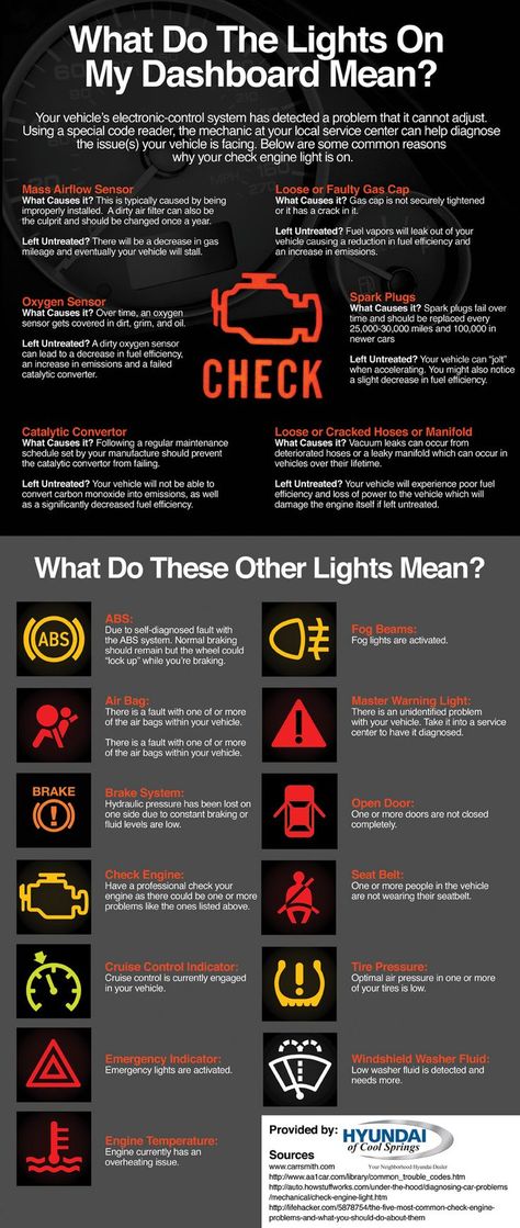
Kucher V.P.
© Legion-Avtodata
You may also be interested in:
This manual is used to check whether the CAN high and CAN low signals are recognized correctly on the bus connection.
Multifunction cable
The CAN bus (Controller Area Network) is a serial bus system with the following features:
Driver: the master device is the active communication partner from which the communication initiative comes. The master has priority and controls the communication. It can send messages to the passive bus user (actuator) via the bus system and, upon request, receive its messages.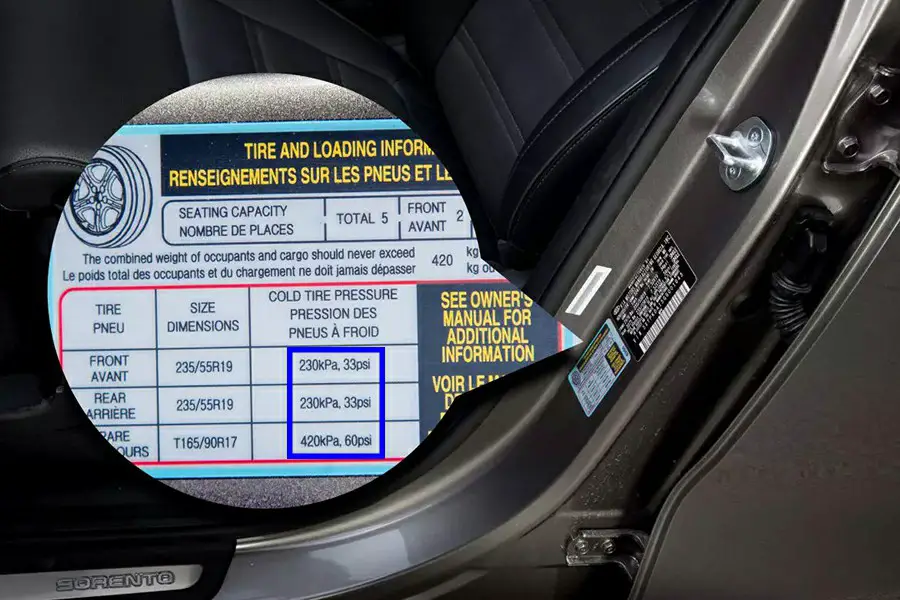
Actuator: the executive device is a passive participant in the communication. It receives a command to receive and transmit data.
Driver system: in a system with a master device, communication participants can at a certain point in time take on the role of master or executive device.
To be clearer if the CAN bus is working properly, it is necessary to observe the bus communication. In this case, it is not necessary to analyze individual bits, but only to make sure that the CAN bus is working. The oscilloscope shows: ”CAN bus appears to be working without disturbance”.
K-CAN:
Low level CAN relative to mass: U min = 1 V and U max = 5 V
CAN high level relative to mass: U min = 0 V and U max = 4 V
Oscilloscope settings for measurements on the K-CAN bus:
1: K-CAN measurement: Ch2 CAN low, Ch3 CAN high
When measuring the voltage between the CAN low (or CAN-High) wire and ground with an oscilloscope, a square wave signal is obtained within the voltage range:
PT-CAN and F-CAN
Low level CAN relative to mass: U min = 1. 5 V and U max = 2.5 V
CAN high level relative to mass: U min = 2.5 V and U max = 3.5 V
These values are approximate and may vary, depending on the bus load, by up to 100 mV.
Oscilloscope settings for PT-CAN (or F-CAN) measurement:
Figure 2: PT-CAN measurement: Ch2 CAN low, Ch3 CAN high
Resistance measurement verification process:
A separate resistance measurement cannot be carried out on the K-CAN bus, as the resistance changes depending on the switching logic of the computer!
To prevent signal reflections, two CAN bus devices (with the maximum distance in the PT-CAN network) are terminated with 120 ohms. Both load resistors are connected in parallel and form an equivalent resistance of 60 ohms. With the supply voltage off, this equivalent resistance can be measured between data lines. In addition, individual resistances can be measured individually.
Instructions for measuring with 60 ohms: Disconnect an easily accessible control unit from the bus. Measure the resistance at the connector between the low and high CAN wires.
Not all vehicles have a terminating resistor on the CAN bus The presence of a built-in terminating resistor on the connected vehicle can be checked using the appropriate wiring diagram.
If the K-CAN or PT-CAN data bus is not working, there may be a short or open in the CAN high or low wire. Or the ECU is faulty.
We reserve the right to typographical errors, typographical errors and technical changes.
Often the main cause of a malfunction in the electronic control system of a vehicle is mechanical damage to the CAN bus or failure of control units hanging on the CAN bus.
Below in the article are methods for diagnosing the CAN bus in case of various malfunctions. As an example, a typical CAN bus diagram on a Valtra T "series tractor is shown.
Legend:
CAN BUS measurements
120 ohm terminating resistors (sometimes referred to as terminators) inside the EC control box and a resistor located next to the TC1 box
If the display (on the side pillar) shows a fault code related to the CAN bus, then this indicates a fault in the wiring of the CAN bus or the control unit.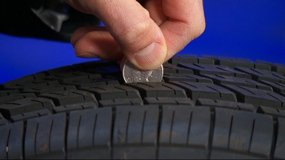
The system can automatically tell which control unit cannot receive information (control unit monitors transmit information to each other).
If the display is flashing or a CAN bus message cannot be transmitted over the bus, a multimeter can be used to locate the faulty CAN bus wiring (or faulty control unit).
CAN bus has no physical damage
If the resistance between the Hi (High) and Lo (Low) wires of the CAN bus (at any point) is approximately 60 ohms, then the CAN bus is not physically damaged.
- The EC and TC1 control units are OK because the terminating resistors (120 ohm) are located in the EC unit and next to the TC1 unit.
The TC2 control unit and the ICL instrument panel are also intact as the CAN bus runs through these units.
CAN bus damaged
If the resistance between the Hi and Lo wires of the CAN bus (at any point) is approximately 120 ohms, then the CAN bus wiring is damaged (one or both wires).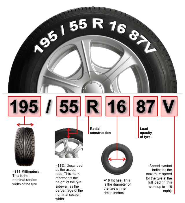
CAN bus has physical damage
If the CAN bus is damaged, determine the location of the damage.
First measure the resistance of the CAN-Lo wire, eg between the EC and TC2 control units.
Therefore, measurements must be made between Lo-Lo or Hi-Hi connectors. If the resistance is approximately 0 ohm, then the wire between the measured points is not damaged.
If the resistance is approximately 240 ohms, then the bus is damaged between the measured points. The figure shows the damage to the CAN-Lo wire between the TC1 control unit and the ICL dashboard.
Short circuit in the CAN bus
If the resistance between the CAN-Hi and CAN-Lo wires is approximately 0 ohms, the CAN bus has a short circuit.
Disconnect one of the control units and measure the resistance between the pins of the CAN-Hi and CAN-Lo connectors on the control unit. If the device is OK, reinstall it.
Then disconnect the next device, take measurements. Proceed in this manner until the faulty device is found. The unit is faulty if the resistance is approximately 0 ohms.
If all units are tested and the measurements still indicate a short circuit, this indicates a fault in the CAN bus wiring. To find the place of damage to the wires, they should be checked visually.
CAN bus voltage measurement
Turn on the power and measure the voltage between the CAN-Hi, CAN-Lo wires and the ground wire.
The voltage must be between 2.4 - 2.7 V.
In order to control systems coherently and harmoniously, to ensure the quality and functionality of data transfer, many automotive manufacturers use a modern system known as the CAN bus. The principle of its organization deserves detailed consideration.
Visually, the CAN bus looks like an asynchronous sequence. Its information is transmitted over two twisted conductors, a radio channel or an optical fiber.
Several devices can control the bus at the same time.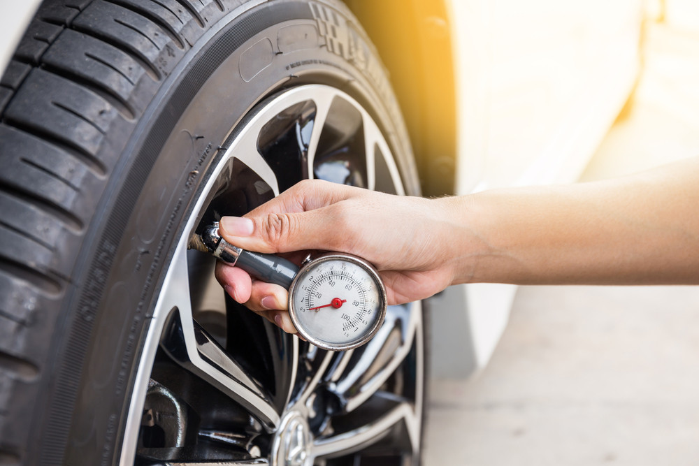 Their number is not limited, and the information exchange rate is programmed up to 1 Mbps.
The CAN bus in modern vehicles is regulated by the "CAN Sorcification version 2.0" specification.
It consists of two sections. Protocol A describes the transfer of information using an 11-bit data transfer system. Part B performs these functions when using the 29-bit version.
CAN has personal clock nodes. Each of them sends signals to all systems simultaneously. The receiving devices attached to the bus determine whether the signal is within their purview. Each system has hardware filtering of messages addressed to it.
One of the most famous today is the CAN bus developed by Robert Bosch. CAN BUS (the system is known under this name) is sequential, where a pulse is given after a pulse. It's called serial bus. If information is transmitted over several wires, then this is a Parallel bus.
I - control units;
II - system communications.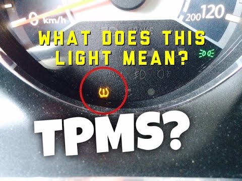
Based on the varieties of CAN bus identifiers, there are two types of markings.
In the case when the node supports 11-bit information exchange format and does not indicate errors on the 29-bit identifier signals, it is marked "CAN2.0A Active, CAN2.0B Passive".
When such generators use both types of identifiers, the bus is labeled "CAN2.0B Active".
There are nodes that support communications in 11-bit format, and when they see a 29-bit identifier in the system, they issue an error message. In modern cars, such CAN buses are not used, because the system must be logical and consistent.
The system operates at two types of signal transmission rates - 125, 250 kbps. The former are intended for auxiliary devices (window regulators, lighting), and the latter provide the main control (automatic transmission, engine, ABS).
Physically, the CAN bus conductor of a modern car is made of two components. The first one is black and is called CAN-High. The second conductor, orange-brown, is called CAN-Low. Thanks to the presented communication structure, a lot of conductors have been removed from the car circuit. In the production of vehicles, this allows you to reduce the weight of the product to 50 kg.
The total network load consists of disparate block resistances that are part of a protocol called CAN bus.
The transmission and reception rates of each system are also different. Therefore, the processing of heterogeneous messages is ensured. According to the description of the CAN bus, this function is performed by the signal converter. It is called the gateway electronic interface.
This device is located in the design of the control unit, but it can be made as a separate device.
The presented interface is also used for the output and input of diagnostic signals. For this, a unified OBD block is provided. This is a special connector for system diagnostics.
There are different types of device shown.
When examining what a CAN bus is, it might seem that it is similar to an aircraft system in terms of the number of programs. However, in order to ensure quality, safety and comfort when driving, no programs will be superfluous.
All control units are connected to the CAN bus by transceivers. They have message receivers that are selective amplifiers.
Description of the CAN bus specifies the receipt of messages on the High and Low conductors in the differential amplifier, where it is processed and sent to the control unit.
The amplifier detects this output as the voltage difference between the High and Low wires. This approach eliminates the influence of external interference.
To understand what a CAN bus and its device is, you should remember its appearance. These are two conductors twisted together.
Since the interference signal is applied to both wires at the same time, the Low voltage value is subtracted from the High voltage during processing.
This makes the CAN bus a reliable system.
The protocol provides for the use of four types of commands when exchanging information via the CAN bus.
I - CAN bus;
II - resistance resistor;
III - interface.
In the process of receiving and transmitting information, a certain time is allotted for one operation. If it exits, an error frame is generated. Error Frame also lasts a certain amount of time. A failed unit is automatically disconnected from the bus when a large number of errors accumulate.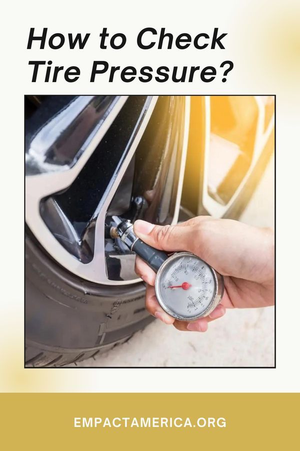
To understand what a CAN bus is, you need to understand its functionality.
It is designed to transmit real-time frames that contain information about a value (for example, a change in speed) or about the occurrence of an event from one transmitter node to program receivers.
The command consists of 3 sections: name, event value, time of observation of the variable.
Key value is given to the indicator variable. If the message does not contain time data, then this message is accepted by the system upon receipt.
When the communication system computer requests a parameter status indicator, it is sent in priority order.
When multiple controllers receive signals on the bus, the system chooses in which order each controller will be processed. Two or more devices can start working at almost the same time. In order to avoid conflict, monitoring is carried out. The CAN bus of a modern car performs this operation in the process of sending a message.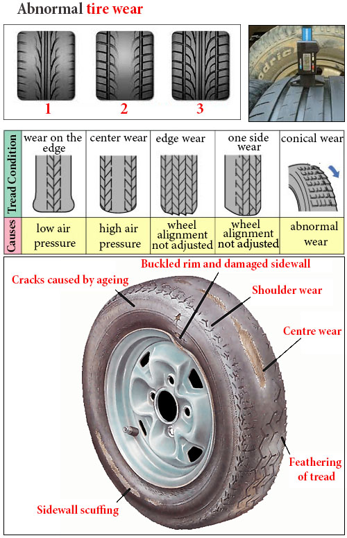
There is a gradation of messages according to priority and recessive gradation. The information having the lowest numeric expression of the arbitration field will win when a collision occurs on the bus. Other transmitters will try to send their frames later if nothing changes.
During the transmission of information, the time specified in it is not lost even if there is a conflict state of the system.
The bus device consists of several elements in addition to the cable.
Transceiver ICs are often found from Philips, as well as Siliconix, Bosch, Infineon.
To understand what a CAN bus is, you need to study its components. The maximum length of the conductor at a speed of 1 Mbit / s reaches 40 m. The CAN bus (also known as CAN-BUS) is endowed with a terminator at the end.
To do this, 120 Ohm resistance resistors are installed at the end of the conductors. This is necessary to eliminate message reflections at the end of the bus and ensure that it receives the appropriate current levels.
The conductor itself can be shielded or unshielded depending on the design. The end resistance can deviate from the classical one and be in the range from 108 to 132 ohms.
When considering vehicle tires, attention should be paid to the engine blocking program.
For this purpose, communication via the CAN bus, iCAN module, has been developed. It connects to the digital bus and is responsible for the corresponding command.
Small in size and attaches to any bus compartment. When the car starts moving, iCAN sends a command to the appropriate blocks, and the engine stalls. The advantage of this program is the absence of signal break. There is an instruction of the electronic unit, after that the message disables the functioning of the corresponding actuators.
This type of lock is characterized by the highest secrecy, and therefore reliability. In this case, errors are not recorded in the memory of the computer. The CAN bus provides all information about the speed and movement of the vehicle to this module.
The iCAN module is installed in any node where the harnesses are located, in the place where the bus is installed. Due to the minimum dimensions and a special algorithm of actions, it is almost impossible to detect blocking by conventional methods when committing theft.
Externally, this module is disguised as various control sensors, which also makes it impossible to detect. If desired, it is possible to configure the operation of the device for automatic protection of car windows and mirrors.
If the vehicle has an engine autostart, iCAN will not interfere with its operation, as it is triggered when the vehicle starts to move.
Having become acquainted with the device and principles of data exchange, which is endowed with a CAN bus, it becomes clear why all modern cars use these technologies in the development of vehicle control.
The presented technology is quite complex in its structure. However, all the functions incorporated into it will provide the most efficient, safe and comfortable driving.
Existing developments help to protect the vehicle even from theft. Thanks to this, as well as a complex of other functions, the CAN bus is popular and in demand.
Since all modern cars have several data bus configurations, diagnosticians and auto electricians are increasingly faced with malfunctions related specifically to data transmission. As a rule, a symptom can be a lack of communication with some block, repeated "U" codes in several blocks related to the same bus. This may be accompanied by numerous active fault lights on the instrument panel.
Today we will discuss CAN bus faults. There are several ways to determine its integrity and normal communication. The best way to do this is with an oscilloscope. But not all oscilloscopes are fast enough to read packets on data buses. Some scanners also have a built-in CAN bus integrity check, such as G-scan 3:
In this article, we will talk about a quick way to diagnose the CAN bus using a multimeter through the diagnostic connector.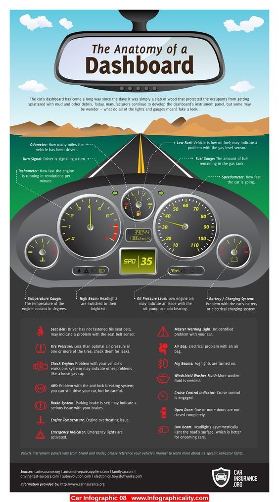 It takes a little time and in any car service there is always a multimeter. So, step by step instructions:
STEP 1: "Low Speed CAN Bus Check for a Short":
Unplug the scanner from the outlet. Turn the ignition key to position 2 (ON). Using a multimeter, we measure the voltage (PIN 14 on the socket and GND). Do we have a voltage of 10.0 volts?
STEP 2: "Low Speed CAN Bus Ground Fault Test":
We find PIN 6 on the outlet and connect the second probe of the oscilloscope to the positive terminal of the battery. Do we have 0 volts? If we find 0 volts here, then we begin to turn off the modules one at a time until voltage appears. If it still does not appear, then the problem is in the CAN bus wiring and it is necessary to determine the location of the alleged short circuit and change the twisted pair.
STEP 3: "Testing the termination resistors":
We turn off the ignition. Disconnect the negative terminal of the battery. We transfer the multitimter to the resistance measurement mode and measure the Resistance between the high and low CAN buses (between PINs 6 and 14). Is the resistance in the range of 53.5 - 67 ohms? If YES, then the test is complete. If the problem persists, then it is absent at the time of measurement and is sporadic. Refer to vehicle wiring diagram, check connectors and other wiring for connector oxidation, kinks, old oscilloscope pinholes, water intrusion, or corrosion. Check the integrity of the connections. If the resistance is not in the range of 53.5 - 67 ohms, then go to the next step.
STEP 4: "High circuit resistance - more than 67 ohms":
If the measured resistance is higher than 67 ohms, then we have a high CAN HIGH or LOW signal, its open, or one of the terminating resistors inside the ECU is damaged. If we have a low circuit resistance (below 53.5 ohms), then go to the next step.