RADIAL TIRE CONDITIONS ANALYSIS GUIDE A Comprehensive Review of Tread Wear and Tire Conditions RADIAL TIRE CONDITIONS ANALYSIS GUIDE A Comprehensive Review of Tread Wear And Tire Conditions © Copyright 1994 The Maintenance Council Printed in U.S.A. Replaces 1984 Out of Service Tire Analysis Guide and Radial Tire Wear Conditions and Causes The procedures contained herein reflect the consensus of the members of The Maintenance Council (TMC) on those items and methods that have delivered the best performance record based on the experience of those present at the meetings of the Council. The procedures contained herein are not exclusive. TMC cannot possibly know, evaluate or advise the transportation industry of all conceivable ways in which a procedure may be undertaken or of the pos- sible consequences of each such practice. Other practices or methods may be as good or better depending upon the particular circumstances involved.
Every carrier who uses the procedures contained herein must first satisfy itself thoroughly that neither the safety of its employees or agents nor the safety or usefulness of any products will be jeopardized by any method selected. The following procedures are not intended nor should they be construed as an endorsement of any particular person, organization or product. For information on obtaining additional copies of this guide, contact The Maintenance Council 2200 Mill Road Alexandria, VA 22314 (703) 838-1763 Or Call American Trucking Associations Customer Service (800) ATA-LINE Order Item # T0121 (TMC/ATA Members) or T0126 (Non-members) II We would like to thank the following companies who participated in the development of this guide by donating their expertise and photographs American Retreaders Association Bandag, Inc. Acknowledgment Bridgestone/Firestone, Inc. Cooper Tire and Rubber Co. General Tire, Inc. Goodyear Tire & Rubber Co. Hankook Tire America Corp. Hawkinson Companies Hercules Tire and Rubber Co.
 KLLM, Inc. Kumho USA, Inc. Michelin Tire Corp. Rema Tip Top/North America, Inc. Roadway Tire Co. Sumitomo Tire Tech International Toyo Tire (U.S.A.) Corp. Truflex/Pang Rubber Co. III Table Of Contents Introduction VIII Glossary XIII I. New Tire (Original Tread) and Casing Conditions 1 A. Bead Area 3 Torn Beads 4 Kinked/Distorted Beads 5 Bead Deformation 6 Burned Beads 7 Reinforce/Chafer Separation 8 Petro/Lubricant Damage 9 Bead Damage From Curbing 10 Bead Area Flow Crack 11 B. Sidewall Area 13 Spread/Damaged Cord 14 Cuts and Snags 15 Sidewall Separation 16 Chain Damage 17 Vehicle/Equipment Damage 18 Damage Induced Sidewall Separation 19 Sidewall Abrasion/Scuff Damage 20 Weathering 21 Impact Break 22 Branding Damage 23 Diagonal Cracking 24 Petroleum Product Damage 25 Forklift Damage 26 Circumferential Fatigue Rupture (Zipper) 27 Open Sidewall Splice 28 Sidewall Bumps (Blisters) 29 Sidewall Penetration 30 Radial Split 31 C. Crown Area 33 Penetrations and Road Hazards 34 Vehicle Damage 35 Forklift Damage/Cuts and Snags 36 Belt Lift/Separation 37 Tread Lift/Separation 38 Brake Skid Damage 39 Tread /Chunking 40 Lug Base Cracking 41 Wild Wire 42 Impact Breaks 43 IV Table Of Contents Chipping/Flaking/Chunking Tread 44 Stone Drilling 45 Regrooving Damage 46 Dynamometer Type Damage 47 Chemical Damage 48 Excessive Wear 49 Rib Tearing 50 Defense Groove Tearing 51 Groove Cracking 52 Spin Damage 53 D.
 Tire Interior 55 Penetrating Objects 56 Open Inner Liner Splice 57 Inner Liner Bubbles, Blisters, & Separations 58 Inner Liner Cracking 59 Pulled/Loose Cords 60 Tearing, Mount/Dismount Damage 61 Foreign Object Inner Liner Damage in Tubeless Tire 62 Run Flat 63 Pinch Stock 64 Impact Break 65 E. Any Area 67 Run Flat 68 Electrical Discharge 69 II. Retread and Repair Conditions 71 Introduction to Retread Conditions 72 A. Holes and Injuries 73 Bad Spot Repair 74 Spot Repair Should Be A Section 75 Improper Nail Hole Repair 76 Improperly Aligned Repair 77 Unfilled Nail Hole Repair 78 Bridged Repair 79 On The Wheel Repair 80 Bad Bead Repair 81 Failed Repair -- Injury Not Removed 82 Bias Repair in Radial Tire 83 V Table Of Contents II. Retread and Repair Conditions (Continued) B. Missing/Loose Tread 85 Bond Line Porosity 86 Tread Separation 87 Tread Chunking At Splice 88 Tread Separation - Repair Related 89 Belt Separation - Repair Related 90 Missed Puncture 91 Tread Edge Lifting 92 C. Cracks 93 Failed Inner Liner Repair 94 Lug Base Cracking 95 Improper Tread Width 96 Open Tread Splice 97 D.
 Bulges/Depressions 99 Skive Failure 100 Repair Related Bulge 101 Buckled Tread 102 E. Miscellaneous 103 Delamination 104 Tread Surface Porosity 105 Wing Lift 106 Failed Repair From Underinflation 107 VI Table Of Contents III. Radial Tire Wear Conditions and Causes 109 Introduction to Radial Tire Wear Conditions and Causes 110 Section A: Steer Axle Tires 111 Shoulder Step/Chamfer Wear 112 Full Shoulder Wear 113 Feather Wear 114 Erosion/River/Channel Wear 115 Cupping/Scallop Wear 116 One Sided Wear 117 Diagonal Wear 118 Eccentric/Out-Of-Round Wear 119 Overall Fast Wear 120 Rib Depression/Punch Wear 121 Erratic Depression Wear 122 Section B: Drive Axle Tires 123 Shoulder Step/Chamfer Wear 124 Heel/Toe Wear 125 Alternate Lug Wear 126 Brake Skid/Flat Spot Wear 127 Overall Fast Wear 128 Section C: Trailer Axle Tires 129 Brake Skid/Flat Spot Wear 130 Diagonal Wear 131 Multiple Flat Spotting Wear 132 Rapid Shoulder Wear - One Shoulder 133 Shoulder Scrubbing/Scuffing 134 Rapid Shoulder Wear - Both Shoulders 135 Erratic Depression Wear 136 One-Sided Wear 137 Erosion/River/Channel Wear 138 Rib Depression/Punch Wear 139 VII Introduction VIII Introduction Determining the causes of tires placed out of service is of vital importance to the fleet operator be- cause of the substantial investment that tires represent.
 To protect your investment in tires, it is necessary to know what caused each tire's demise. This publication will lead to cost savings through providing guidance and help in the following areas: 1. Eliminating causes of failures if possible. 2. Retreading and repairing tires and placing them back into service. 3. Presenting tires for warranty credit when applicable. 4. Improving tire maintenance and tire selection if necessary. Tire grading should be done prior to the tire being placed in a “scrap pile.” After a tire has been dismounted from the rim and before it is rolled out the tire shop door, the tire should be inspected with the following questions in mind: 1. Is the tire serviceable? 2. Is it repairable or retreadable? 3. Could it be used in a limited service operation? 4. Should the tire be presented to the original manufacturer or retreader for warranty? 5. If none of the above apply, is it strictly junk? These questions must be answered before the tire is placed in the scrap pile since the tire may lose its usefulness to rust while waiting in the pile to be graded.
 Any usable tire should be stored in a dry covered area. Once it is determined that a tire should be scrapped, the scrap pile itself should be organized. Instead of piling tires randomly, arrange them in lines, leaning one against the other. One line should be designated for originals, one for 1st caps, one for 2nd caps, etc. Bias tires should be separated from radials. An organized scrap pile will allow you to make generalized conclusions at a glance in regards to failed tires; i.e., 1. If a large percentage of tires fail due to a certain operational condition, it may be that the tire is not suitable for the service application. 2. If a large percentage of failed tires are of one brand when several makes of tires are used, it may be that you have a problem with that manufacturer's tires. While some deductions can be made simply by looking at an organized scrap pile, more exact conclu- sions can be derived regarding tire performance when tire records are maintained. Accurate and simple records which include causes of failure, cap numbers, tread depths, etc.
 are extremely impor- tant and helpful when purchasing decisions must be made. IX
A Comprehensive Review of Tread Wear
and Tire Conditions
ANALYSIS GUIDE
RADIAL TIRE CONDITIONS
Copyright 1994 The Maintenance CouncilPrinted in U.S.A.
Replaces 1984 Out of Service Tire Analysis Guideand Radial Tire Wear Conditions and Causes
RADIAL TIRECONDITIONSANALYSISGUIDEA ComprehensiveReview of Tread WearAnd Tire Conditions
For information on obtaining additional copies of this guide, contactThe Maintenance Council2200 Mill RoadAlexandria, VA 22314(703) 838-1763
Or Call American Trucking Associations Customer Service(800) ATA-LINEOrder Item # T0121 (TMC/ATA Members) or T0126 (Non-members)
The procedures contained herein reflect the consensus of the members of TheMaintenance Council (TMC) on those items and methods that have deliveredthe best performance record based on the experience of those present at themeetings of the Council. The procedures contained herein are not exclusive.TMC cannot possibly know, evaluate or advise the transportation industry ofall conceivable ways in which a procedure may be undertaken or of the pos-sible consequences of each such practice. Other practices or methods may beas good or better depending upon the particular circumstances involved.
Every carrier who uses the procedures contained herein must first satisfy itselfthoroughly that neither the safety of its employees or agents nor the safety orusefulness of any products will be jeopardized by any method selected.
The following procedures are not intended nor should they be construed as anendorsement of any particular person, organization or product.
II
Acknowledgment
We would like to thank the following companieswho participated in the development of this guideby donating their expertise and photographs
American Retreaders Association
Bandag, Inc.
Bridgestone/Firestone, Inc.
Cooper Tire and Rubber Co.
General Tire, Inc.
Goodyear Tire & Rubber Co.
Hankook Tire America Corp.
Hawkinson Companies
Hercules Tire and Rubber Co.
KLLM, Inc.
Kumho USA, Inc.
Michelin Tire Corp.
Rema Tip Top/North America, Inc.
Roadway Tire Co.
Sumitomo Tire
Tech International
Toyo Tire (U.S.A.) Corp.
Truflex/Pang Rubber Co.
III
Table Of ContentsIntroduction VIIIGlossary XIII
I. New Tire (Original Tread) and Casing Conditions 1
A. Bead Area 3Torn Beads 4Kinked/Distorted Beads 5Bead Deformation 6Burned Beads 7Reinforce/Chafer Separation 8Petro/Lubricant Damage 9Bead Damage From Curbing 10Bead Area Flow Crack 11
B. Sidewall Area 13Spread/Damaged Cord 14Cuts and Snags 15Sidewall Separation 16Chain Damage 17Vehicle/Equipment Damage 18Damage Induced Sidewall Separation 19Sidewall Abrasion/Scuff Damage 20Weathering 21Impact Break 22Branding Damage 23Diagonal Cracking 24Petroleum Product Damage 25Forklift Damage 26Circumferential Fatigue Rupture (Zipper) 27Open Sidewall Splice 28Sidewall Bumps (Blisters) 29Sidewall Penetration 30Radial Split 31
C. Crown Area 33Penetrations and Road Hazards 34Vehicle Damage 35Forklift Damage/Cuts and Snags 36Belt Lift/Separation 37Tread Lift/Separation 38Brake Skid Damage 39Tread /Chunking 40Lug Base Cracking 41Wild Wire 42Impact Breaks 43
IV
Table Of Contents
Chipping/Flaking/Chunking Tread 44Stone Drilling 45Regrooving Damage 46Dynamometer Type Damage 47Chemical Damage 48Excessive Wear 49Rib Tearing 50Defense Groove Tearing 51Groove Cracking 52Spin Damage 53
D. Tire Interior 55Penetrating Objects 56Open Inner Liner Splice 57Inner Liner Bubbles, Blisters, & Separations 58Inner Liner Cracking 59Pulled/Loose Cords 60Tearing, Mount/Dismount Damage 61Foreign Object Inner Liner Damage in Tubeless Tire 62Run Flat 63Pinch Stock 64Impact Break 65
E. Any Area 67Run Flat 68Electrical Discharge 69
II. Retread and Repair Conditions 71
Introduction to Retread Conditions 72
A. Holes and Injuries 73Bad Spot Repair 74Spot Repair Should Be A Section 75Improper Nail Hole Repair 76Improperly Aligned Repair 77Unfilled Nail Hole Repair 78Bridged Repair 79On The Wheel Repair 80Bad Bead Repair 81Failed Repair -- Injury Not Removed 82Bias Repair in Radial Tire 83
V
II. Retread and Repair Conditions (Continued)
B. Missing/Loose Tread 85Bond Line Porosity 86Tread Separation 87Tread Chunking At Splice 88Tread Separation - Repair Related 89Belt Separation - Repair Related 90Missed Puncture 91Tread Edge Lifting 92
C. Cracks 93Failed Inner Liner Repair 94Lug Base Cracking 95Improper Tread Width 96Open Tread Splice 97
D. Bulges/Depressions 99Skive Failure 100Repair Related Bulge 101Buckled Tread 102
E. Miscellaneous 103Delamination 104Tread Surface Porosity 105Wing Lift 106Failed Repair From Underinflation 107
Table Of Contents
VI
Table Of Contents
III. Radial Tire Wear Conditions and Causes 109
Introduction to Radial Tire Wear Conditions and Causes 110
Section A: Steer Axle Tires 111Shoulder Step/Chamfer Wear 112Full Shoulder Wear 113Feather Wear 114Erosion/River/Channel Wear 115Cupping/Scallop Wear 116One Sided Wear 117Diagonal Wear 118Eccentric/Out-Of-Round Wear 119Overall Fast Wear 120Rib Depression/Punch Wear 121Erratic Depression Wear 122
Section B: Drive Axle Tires 123Shoulder Step/Chamfer Wear 124Heel/Toe Wear 125Alternate Lug Wear 126Brake Skid/Flat Spot Wear 127Overall Fast Wear 128
Section C: Trailer Axle Tires 129Brake Skid/Flat Spot Wear 130Diagonal Wear 131Multiple Flat Spotting Wear 132Rapid Shoulder Wear - One Shoulder 133Shoulder Scrubbing/Scuffing 134Rapid Shoulder Wear - Both Shoulders 135Erratic Depression Wear 136One-Sided Wear 137Erosion/River/Channel Wear 138Rib Depression/Punch Wear 139
VII
Introduction
VIII
Determining the causes of tires placed out of service is of vital importance to the fleet operator be-cause of the substantial investment that tires represent. To protect your investment in tires, it isnecessary to know what caused each tire's demise. This publication will lead to cost savings throughproviding guidance and help in the following areas:
1. Eliminating causes of failures if possible.2. Retreading and repairing tires and placing them back into service.3. Presenting tires for warranty credit when applicable.4. Improving tire maintenance and tire selection if necessary.
Tire grading should be done prior to the tire being placed in a scrap pile. After a tire has beendismounted from the rim and before it is rolled out the tire shop door, the tire should be inspected withthe following questions in mind:
1. Is the tire serviceable?2. Is it repairable or retreadable?3. Could it be used in a limited service operation?4. Should the tire be presented to the original manufacturer or retreader for warranty?5. If none of the above apply, is it strictly junk?
These questions must be answered before the tire is placed in the scrap pile since the tire may lose itsusefulness to rust while waiting in the pile to be graded. Any usable tire should be stored in a drycovered area.
Once it is determined that a tire should be scrapped, the scrap pile itself should be organized. Insteadof piling tires randomly, arrange them in lines, leaning one against the other. One line should bedesignated for originals, one for 1st caps, one for 2nd caps, etc. Bias tires should be separated fromradials. An organized scrap pile will allow you to make generalized conclusions at a glance in regardsto failed tires; i.e.,
1. If a large percentage of tires fail due to a certain operational condition, it may be that thetire is not suitable for the service application.
2. If a large percentage of failed tires are of one brand when several makes of tires are used, itmay be that you have a problem with that manufacturer's tires.
While some deductions can be made simply by looking at an organized scrap pile, more exact conclu-sions can be derived regarding tire performance when tire records are maintained.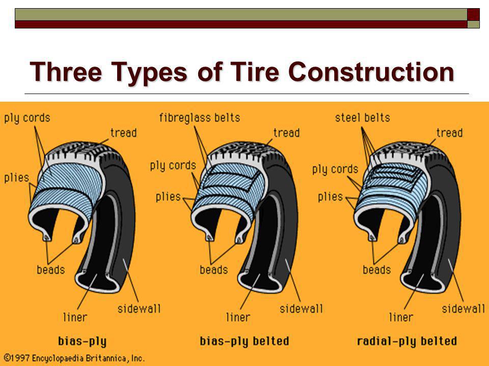 Accurate andsimple records which include causes of failure, cap numbers, tread depths, etc. are extremely impor-tant and helpful when purchasing decisions must be made.
Introduction
IX
Remove all foreign objects and water from the tire and place on a spreader in a well-lighted area. Forinspection purposes, the tire can be divided into seven areas:
1. Tread or Crown Area.2. Upper Sidewall and Shoulder Area on DOT side.3. Upper Sidewall and Shoulder Area on non-DOT side.4. Lower Sidewall and Bead Area on DOT side.5. Lower Sidewall and Bead Area on non-DOT side.6. Interior on DOT side.7. Interior on non-DOT side.
For DOT explanation, see TMC Recommended Practice 210A; also see Glossary, page XIII.
Begin by inspecting the tread area. Look for punctures, cuts, foreign objects and any distortion in thetread. Move to the upper and lower sidewalls of the DOT side and then the non-DOT side of the tire.Inspect these areas for separation between casing components. This is usually denoted by cracks orbulges, damage to the bead and bead wires, deterioration of rubber caused by oil and grease, weatherchecking, cuts and penetrations. Then examine both sides of the interior looking for wrinkling orcorrugations in the inner liner caused by running flat or underinflated, blisters or lumps, cracks andlooseness. Mark all damage, punctures, and separations with a paint stick as you find them. Rotatethe tire as necessary for thorough inspections. Use a probe to determine the origin and extent ofdamage. Inspect the complete tire prior to determining the cause of failure (i.e., often a separation in atire sidewall may be caused by a nail hole
Close
Moscow and region
Tires are one of the most important inventions of all mankind. It is worth noting that a modern car would not have become such a successful and efficient vehicle without pneumatic tires. Outwardly, the tires are little different from each other, with the exception of the tread pattern and their radius. All of them consist of various rubber compounds and fillers. Some sizzle - others don't. The round shape of the tires is maintained by the carcass. The carcass directly affects many tire characteristics.
Diagonal frame
Radial frame
Let's consider two types: tires with a diagonal and a radial carcass. Despite the external similarity, they are structurally very different.
Frame
The bias tire has a carcass made of
multi-ply cord. As a rule, the number of layers
is a multiple of two. Textile cords of different layers
are located at an angle of 35° to 40° to each other
and intersect exactly in the middle of the tire
protector.
Frame
Breaker Belt
Frame
In radial tires, the cords are located at a
angle of 90° and are located along the entire tire
tread. And those sections of the tire that
are located in the contact patch with the road surface
are reinforced with a steel cord (it is also called a belt belt
).
In addition to the difference in the arrangement of cords, there are many other differences
- Cord threads for diagonal tires are made of nylon or kapron, for radial tires they are made of steel.
- Bias tires can have several layers of cord - from two or more, radial tires have only 1.
- Bias tires, as a rule, have two bead rings, with a radial one.
- Most bias tube tires, tubeless radials.
Functional differences of radial tires
— Better contact with the road. Radial tires have a larger contact patch compared to bias
tires.
- The weight of a radial tire and a bias tire with the same radius will be different. Lighter tire with radial carcass
ply.
— A radial tire can carry more loads (15 to 20%) than a bias tire.
- The carcass of a radial tire has better thermal conductivity, due to this, heat dissipation in such tires
will be better.
Some differences of bias tires
— Tires with a diagonal carcass have a well-protected sidewall and are less afraid of lateral damage
compared to radial tires. In this case, diagonal tires are more protected from
side injuries.
- Bias tires are cheaper than radial tires.
- Despite their shortcomings, bias tires have found their way and continue to be used in
commercial vehicles. Radial carcass tires also found their place in a large number of
vehicles. Almost all car factories produce passenger cars equipped with tires
with radial carcass.
* When taking tires for repair, carefully check their general condition. Explore all tires for hidden defects. Particular attention must be paid on the condition of the boards.
* To achieve a quality repair the following conditions are required: - organized in accordance with sanitary standards and workflow process places; - appropriate lighting sanitary standards; - past training and certification of personnel; - all materials must be recommended for use by the company “Thermopress” and tested for compliance with the warranty term. - storage of materials and equipment must be carried out with compliance with the relevant requirements, set out in the accompanying instructions and accompanying documents.
* The manufacturer reserves the right to any changes for the purpose of technical improvements.
* When choosing plasters, tools and equipment, use valid tables and instructions.
Attention: For car repair tires by hot vulcanization should use special thermocouples with black adhesive layer and index "t°" in designation.
Safety note:
* When working with tools, observe the requirements of the relevant regulations for safety, where it is necessary, use protective equipment such as safety goggles, gloves, respirators, etc.
* When handling solutions, observe safety measures indicated on the labels, exhaust ventilation is required.
* Operate only on serviceable equipment, use the correct tool.
For car tire repair hot vulcanization recommended use vulcanizers "Complex""
Solutions listed in this leaflet can be supplied in packaging other than from that listed in the catalog.
This manual introduces repair work that is carried out on the sidewall. Running track and tire shoulder are being repaired similarly.
1. When taking tires for repair, carefully check their general condition. Explore all tires for hidden defects. Pre-determine maintainability tires, for this measure the dimensions damage, and according to the table previously select patch number.
Measure the distance from the edge of the damage to the edge of the tire bead. The size must be greater than or equal to the value specified in the patch selection table.
If the damage exceeds allowable standards, then repair the tire it is forbidden.
2. The tire must be be dried thoroughly. Tire drying it is recommended to produce in a dry heated room. To speed up allowed to dry the damaged area a lamp or a jet of heated air using a fan heater (art. no. 05 010), while heating must not be allowed rubber above 80 ° C.
Wear safety goggles!
3. Treat the damaged area with inside and outside cleaner Liquid Buffer and use a scraper to remove pollution.
4. Cut out the damaged rubber with a knife or cap cutter (art. no. 04 008…04 0012). Remove damaged cord ends (Fig. 2). When repairing a treadmill remove loose, damaged or rusty breaker wire with wire cutters.
5. Round off the ends of the cracks with sharp pin rougher (art. no. 04 110) or a specially sharpened tube.
6. Treat the damage funnel in steel cord zone with a cut-off disc (art. no. 04 420) (fig. 3) or grinding cone (art. no. 04 400) and then process rubber surface with a rougher rings (art. no. 04 160) so that cup-shaped funnel (fig. 4)
ATTENTION! Finished rubber surface should be rough (by no means smooth). During processing, do not burn rubber, for this final roughening perform at low tool speeds (up to 750 rpm)
7. Properly Prepared Funnel damage (Fig. 5).
ATTENTION! Do not contaminate the stripped surface and do not treat with cleaner Liquid Buffer. Do not allow intermediate storage to avoid contamination and surface oxidation.
8. Measure the size of the damage. At repairing bias tires find the number PR (number of cord plies) indicated on tire sidewall. Choose the one you want patch in accordance with current tables and mark the patch number on chalk tire. To calculate the time vulcanization measure the maximum wall thickness at the site of damage and make a mark on the surface of the tire.
9. For the correct installation of the thermal patch swipe on the inside of the tire in the center of the place of repair auxiliary lines in radial and axial directions (Fig. 6). When repairing the sidewall of the diagonal tires must use special side patches with the index “B”, which allow you to install them closer to the edge sides. For ease of use, spread tire bead with bead expander (art. no. 06 003).
10. Apply in the center of each side patch auxiliary lines (Fig. 7).
11. Install the thermal patch (arrow in the direction of the edge of the bead) to the inner side of the tire at the point of damage so that so that the auxiliary lines on the bus and patch matched. Circle the thermal patch along the contour with an allowance of 5-10 mm
12. Cases of damage. Sketches 8 a, b, c show the installation of a thermal patch on the principle of alignment of the center of damage and the center of the thermal patch. Sketch 8 g shows the possibility of repair damage near unrepairable zones, while the center of damage is not coincides with the center of the thermal patch. IN In this case, the edge of the patch should overlap as close to the edge as possible sides.
13. On the inner surface of the tire in repair site must be carefully Apply Liquid Buffer Cleaner to area larger than the selected thermal patch, carefully remove dirt with a scraper (art. no. 04 022). At the same time, avoid getting Liquid Buffer on the treated surface funnels (see warning to item 7).
Rotate the tire so that the repair turned sideways, and give dry for 10-15 minutes.
14. Process the tire inside the marked plot (Fig. 9) using contour circle (art. no. 04 300) or round metal brushes (art. no. 04 340). When repairing tubeless tires must be completely removed loose sealed layer to a layer of dense rubber.
ATTENTION! Processing very carefully so as not to damage cord threads.
15. Remove dust and crumb rubber inside and outside the tire at the point of repair using sweeping brush or vacuum cleaner (Fig. 10).
Do not clean with compressed air containing oil or moisture.
16. Check the quality of the rubber layer on treated area. Completely remove soft, rolling when peeled off rubber particles.
ATTENTION! Finished rubber surface should be rough (by no means smooth). During processing, do not burn rubber, for this final roughening perform at low tool speeds (up to 750 rpm) with a wire brush (art. No. 04 340).
17. Apply evenly to the prepared for installing thermal plaster surface tires first layer of thermal solution (art. no. 10 600). Drying time - 60 minutes (rear side of the finger - sticking should not be).
18. After the first coat has dried thermal solution on the surface of the tire apply a second layer. Drying time of the second layer 15-20 minutes (sample back side finger should feel light adhesion). For timing use timer (art. no. 11 001)
19. Remove the protective film from the side adhesive rubber from the middle approximately 5-7cm in both directions (protective film from the top side of the thermocouple must be left).
20. Remove the onboard expander. Patch with free middle zone apply to the place of repair, combining auxiliary lines on the patch and splint. Roll on middle of patch with roller
21. Remove both parts of the protective cover one by one. adhesive films. With and without effort roll the entire surface patch with a roller (art. no. 05 002).
22. When repairing tubeless tires, remote during roughening the sealed layer inside the tire around the thermal patch needs to be restored. For this you need to cut strips of raw rubber (1 mm) and roll them with a roller around the perimeter plaster in such a way as to cover buffed tire surface around patch.
23. Coat the surface of the funnel with two thermal solution layer (art. no. 10 600). Time drying - 60 minutes (sample with the back side finger - sticking should not be). After the first layer has dried, apply second layer. Drying time of the second layer 15-20 minutes (test with the back of the finger you should feel a slight stickiness) (Fig. 12). To keep track of time, use timer.
ATTENTION! To reduce the time the first layer is allowed thermal solution simultaneously to the surface under the patch and on the damage funnel.
24. To fill the funnel damage tires cut strips of raw rubber (3mm) 10-15mm wide and heat them for special plate (art. no. 11 011) (Fig. 13).
25. Do a serial filling the funnel with strips of raw rubber (3mm), carefully rolling them to each other with the help of roller, preventing the formation of air bubbles (Fig. 14).
26. Trim the bumps with a knife, while the level of crude rubber filling funnel, must exceed the overall level tire surface by at least 3 mm for tires L / A and 5 mm for tires G / A (Fig. 15).
15).
27. Vulcanize the site repair with vulcanizers "Complex-1", "Complex-2" or "Complex-3" providing mode simultaneous vulcanization of the patch and funnel damage.
Follow instructions for the operation of vulcanizers!
Tire curing time at temperature vulcanization 140 ° C develops from: - 30 minutes to warm up heaters - 5 minutes each millimeter of tire thickness, taking into account the thickness patch. - when repairing tractor and all-terrain tires with a deep profile it is necessary to increase the curing time by 50%.
28. After the curing regimen the tire must cool down under pressure to t = 90°C.
29. Remove repaired tire from the vulcanizer.
30. After vulcanization check the quality of the repaired surface. Rubber surface at the repair site should be dense, without air pores. The presence of air pores indicates insufficient pressure in the process vulcanization.
31. Sand the outside of the place repair to the level of the main surface tires.