Knowing your rear end’s gear ratio is crucial when you are considering a transmission upgrade, needing to calibrate the speedometer gear in your transmission, selecting the proper gear sets in a transmission, or even getting professional help with a new axle ratio for your application.
There are ways to determine your gear ratio without having to open your differential.
The differential also called a pumpkin, is a mess if you open it up.
The gear oil is smelly, it takes a lot of time, and you want to avoid opening it up if possible.
So, there are some places you can check and things you can do to determine your gear ratio without going through all that.
Check the Differential Cover
There are two other places that you can check…On the Axle and the differential cover itself
The axle may have a sticker, and on the differential cover, you might have a small metal tag that’s sticking out that will have the gear ratio stamped on it.
Click this link for some help with reading Tags
(Hover over image to enlarge)
Do a Driveshaft Turn Test.
Before you can begin identifying the gear ratio, you will also need to know if the rear end is a “posi” or open differential.
This is required because identifying gear ratios is a little different for each unit.
To begin with, raise the rear of the car with a floor jack and place a good set of jack stands under the car on the frame or rear-axle housing.
Once supported, place the transmission in Neutral and turn one of the rear wheels.
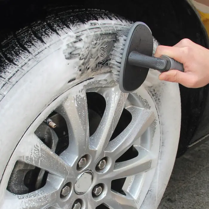
While doing this test, some guys like to use soapstone, chalk, or tape to put a mark on the tire and driveshaft to make counting the total revolutions easier. If you also want to do that, a modeler’s paint marker also works well. I typically focus on an already supplied marking of some sort on the tire (like a certain letter of the tire’s name) and one of the universal-joint bolts and use those as your reference. If using a paint marker, make a large, visible dot on both the inside of the tire and on the driveshaft.
(we used tape)
When you have your marks applied, if the car has a posi unit, both tires will be in the air.
Rotate the marked tire one revolution while counting how many times the driveshaft rotates.
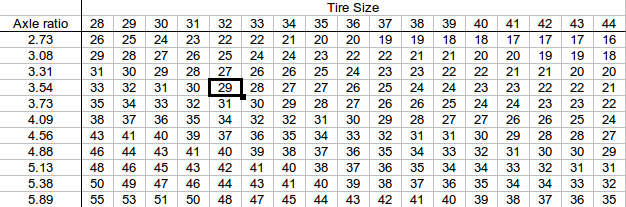
eg, If your driveshaft made 3 3/4 revolutions, that would determine a 3.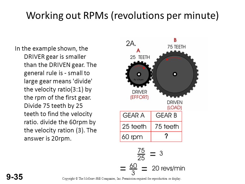 73 gear ratio.
If you get approximately 2 3/4 revolutions, you have a 2.76 gear ratio.
Like previously mentioned, if your car has an open differential (non-positraction), you will want to perform the check with one rear wheel on the ground. Again, mark the inside of the tire and a spot on the driveshaft with your paint marker. Now, rotate the suspended tire two revolutions and count the number of driveshaft turns. The reason to make two revolutions is the open differential actually rotates half as many times as a ‘posi,’ because of the design of the “open” gear operation.
if the driveshaft turned 3 3/4 revolutions for two rotations of the tire, you have a 3.73 gear. A driveshaft that rotates 2 3/4 times announces a 2.76 gear ratio.
Check the Ring Gear Stamping
If you have access to the differential and the cover is already removed look on the ring gear turn it until you can see the stamping, you’ll see the number of teeth.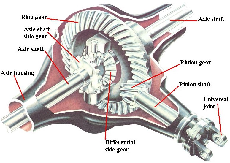
That is the number of teeth for the ring gear and the pinion gear.
If you are not sure about your results when using the wheel rotation method, the number of teeth is stamped on the ring gear. The small number is the pinion-gear tooth count. The large number is the ring-gear tooth count. To find the gear ratio, divide the big number by the little number.
In the example to the left, 37 ÷ 12 = 3.083333. These are 3.08 gears.
(Hover over image to enlarge)
Calculate the Ring & Pinion Teeth
If you can’t find a stamping or it is unreadable.
Then you can always count all the teeth on the pinion & ring gears.
Once you have those two numbers divide the number of teeth from the ring gear by the number of teeth that are on the pinion gear.
The answer will be your gear ratio.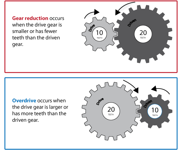
(Hover over image to enlarge)
Hopefully, we have provided you with some knowledge that every car guy should know & will help with any decisions about changing gears a little less challenging.
If you have any questions as always we are here to help
call: PH – 208-453-9800 OR email us at: [email protected]
You just bought your latest hot rod, but in true car-guy fashion, you think an upgrade is in order. You have decided that a rearend gear swap is the first place you want to go. Before you can decide if an upgrade is in order, don’t you think you should first find out what gear ratio your car already has in the rear?
How to determine what gear ratio is under a car is a question that I get asked quite often. I am surprised at the frequency of the question, since finding the answer is a really simple task. While you can pull the rearend cover and look for the ratio numbers on the ring gear, there is an easier way. In fact, it only requires you have a floor jack and a couple of jackstands. To help you guys make gear identification easy, I decided to put together a small outline of how you can find out what gears you actually have without opening the rearend.
If you are not sure about your results when using the wheel rotation method, the number of teeth is stamped on the ring gear. The small number is the pinion-gear tooth count. The large number is the ring-gear tooth count. To find the gear ratio, divide the big number by the little number. In the above example, 37 ÷ 12 = 3.083333. These are 3.08 gears.
Knowing your rearend’s gear ratio is crucial when you are considering a transmission upgrade, needing to calibrate the speedometer gear in your transmission, selecting a torque converter, or even getting professional help with camshaft selection.
Before you can begin identifying the gear ratio, you will also need to know if the rearend is a “posi” or open differential. This is required because identifying gear ratios is a little different for each unit.
To begin with, raise the rear of the car with a floor jack and place a good set of jackstands under the car on the frame or rear-axle housing. Once supported, place the transmission in Neutral and turn one of the rear wheels. If the opposing wheel spins in the same direction, you have a posi – or limited-slip – differential. If this is the case, you can leave both jackstands under the car. If you spin one of the rear wheels and the other one rotates in the opposite direction, you have an open differential. In this case, you will need to remove one of the jackstands and put one tire back on the ground.
A soapstone marking on the driveshaft, and the "A" in the tire lettering are used as the markers.
While doing this test, some guys like to use soapstone or chalk to put a mark on the tire and driveshaft to make counting the total revolutions easier. If you also want to do that, a modeler’s paint marker also works well.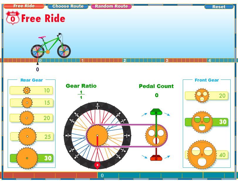 I typically focus on an already supplied marking of some sort on the tire (like a certain letter of the tire’s name) and one of the universal-joint bolts and use those as my reference. If using a paint marker, make a large, visible dot on both the inside of the tire and on the driveshaft.
When you have your marks applied, if the car has a posi unit, both tires will be in the air. Rotate the marked tire one revolution while counting how many times the driveshaft rotates. Let’s say your driveshaft made 3 3/4 revolutions, that would determine a 3.73 gear ratio. If you get approximately 2 3/4 revolutions, you have a 2.76 gear ratio.
Like previously mentioned, if your car has an open differential (non-positraction), you will want to perform the check with one rear wheel on the ground. Again, mark the inside of the tire and a spot on the driveshaft with your paint marker. Now, rotate the suspended tire two revolutions and count the number of driveshaft turns.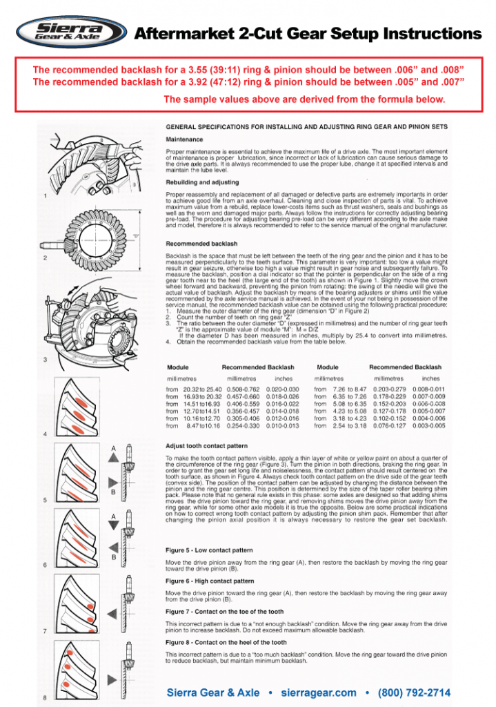 The reason to make two revolutions, is the open differential actually rotates half as many times as a posi, because of the design of the “open” gear operation. Again, if the driveshaft turned 3 3/4 revolutions for two rotations of the tire, you have a 3.73 gear. A driveshaft that rotates 2 3/4 times announces a 2.76 gear ratio.
Hopefully, this little tutorial will give some knowledge that every car guy should know and makes any decisions about changing gears a little less daunting.
Gears are used not only to transmit power, but also to provide a customizable mechanical advantage for the mechanism. As discussed in the introduction to this box, in some cases the motor itself has sufficient power to perform a particular task, but the output of the motor does not meet the requirements. An electric motor that spins VERY fast but with very little torque is not suitable for lifting a heavy load. In such cases, it becomes necessary to use a gear ratio to change the output characteristics and create a balance of torque and speed.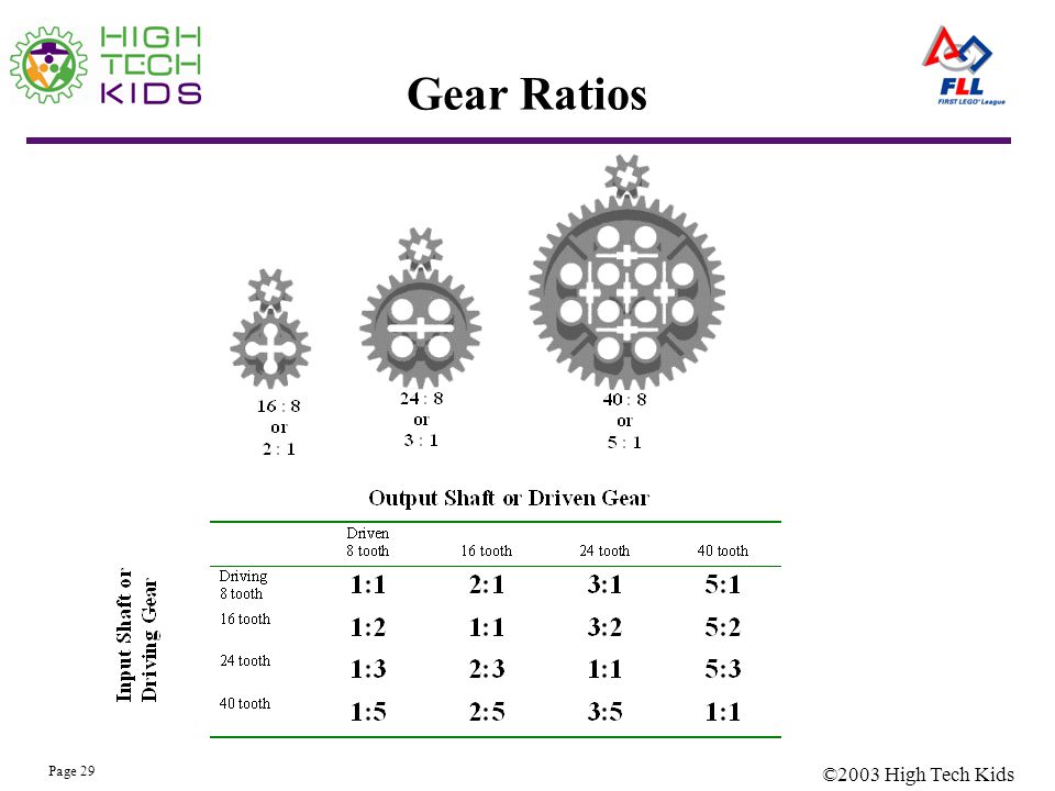
Imagine a bicycle: a cyclist has limited power and wants to make the most of that power at any given time.
Changing the mechanical advantage changes the driving speed. Power is the amount of work done per unit of time. The more work. the slower the execution speed.
Example 8.1
Example 8.1 shows that if the lever moves 1 meter on the entry side, the lever moves 4 meters on the exit side. The difference is proportional to the ratio between the lengths of the levers.
Outlet length / Inlet length = 8 / 2 = 4
Interestingly, both distances are covered in the same time. Let's imagine that the input lever moves 1 meter in 1 second, so the input speed is 1 meter per second. At the same time, at the exit, a displacement of 4 meters also occurs in 1 second, so the speed of movement here is 8 meters per second. The output speed is MORE than the input speed due to the ratio between the lengths of the levers.
Example 8.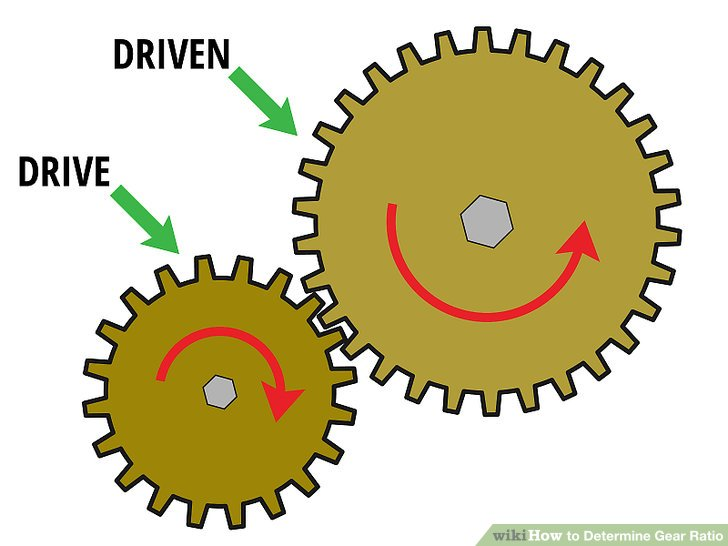 2
2
Example 8.2 shows the same system as in Example 8.1, but now the input is subjected to a force of 4 Newtons. What is the net force at the output?
First of all, it is necessary to calculate the applied torque at the center of rotation caused by the input force using the formulas from Block 7:
Torque = Force x Distance from the center of gravity = 4 N x 2 m = 8 N.m it is necessary to calculate the resultant force at the output:
Force = Torque / Distance = 8 Nm / 8 m = 1 newton will be displaced by 4 meters under the influence of a force equal to 1 newton. With less force, the lever moves faster!
We can see how mechanical advantage (expressed in the form of levers) can be used to control the input force in order to obtain the required output. Transmissions work on the same principle.
The spur gear is essentially a series of levers. The larger the diameter of the gear, the longer the lever.
Example 8.3
As shown in Example 8.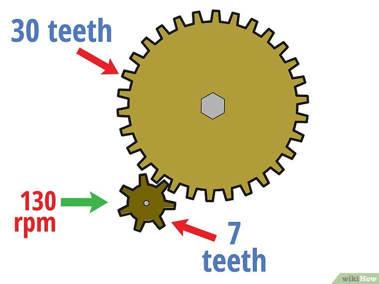 3, the result of the torque applied to the first gear is a linear force at the tips of its teeth. The same force acts on the tips of the teeth of the gear with which the first gear meshes, causing the second to rotate under the action of a torque. The diameters of the gears become the length of the levers, while the change in torque is equivalent to the ratio of the diameters. If the small gears drive more gears, the torque increases. If the large gears drive the small gears, the torque is reduced.
Example 8.4
In example 8.4, if the input 36 tooth gear rotates one tooth (d = 1 tooth width), this means that it rotates 1/36th of its full revolution (a1 = 360 / 36 = 10 degrees). Turning, it sets in motion a 60-tooth gear, forcing the latter to move also by 1 tooth. However, for a 60 tooth gear, this means only 1/60th of a full turn (a2 = 360 / 60 = 6 degrees).
When the small gear travels a certain distance in a given time interval, the large gear travels a shorter distance.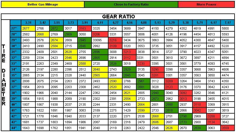 This means that the large gear rotates more slowly than the small one. This principle works both ways. If the smaller gears drive more gears, the speed will decrease. If the large gears drive the small gears, the speed increases.
Examples 8.1 to 8.4 show that the ratio between the sizes of two meshed gears is proportional to the change in torque and speed between them. This is called the gear ratio.
As discussed above, the number of teeth on a gear is directly proportional to its diameter, so you can simply count the teeth instead of the diameter to calculate the gear ratio.
The gear ratio is expressed as (drive gear teeth) : (driven gear teeth), so the above gear pair can be described as 12:60 (or 36 to 60).
The gear ratio is calculated as (driven gear teeth) / (driven gear teeth)
Therefore gear ratio = driven gear teeth / drive gear teeth = 60/36 = 1.67
As discussed above, the gear ratio is expressed as (drive gear teeth) : (driven gear teeth), so the pair of gears shown above can be expressed as 12:60 (or 12 to 60).
The gear ratio is calculated using the formula (drive gear teeth) / (drive gear teeth)
Therefore gear ratio = Drive gear teeth / Drive gear teeth = 60/12 = 5
Looking at the example above...
Second shaft overload torque limit can be calculated as:
Output torque = Input torque x Gear ratio
Output torque = 1.5 N.m x 5 = 7.5 N.m
Second shaft free speed can be calculated from:
Output speed = Input speed / Gear ratio = 100 rpm / 5 = 20 rpm
The second shaft thus rotates at a free speed of 20 rpm, with a limiting overload torque of 7.5 Nm. As the speed decreases, the torque increases.
For the second example, calculations can be made in the same way.
Gear Ratio = Drive Gear Teeth / Drive Gear Teeth = 12/60 = 0.2
Output Torque = Input Torque x Gear Ratio = 1.5 N.m x 0.2 = 0.3 N.m
Output Speed = Input Speed / Gear Ratio = 100 rpm / 0.2 = 500 rpm
The second shaft thus rotates at a free speed of 500 rpm, with a limiting overload torque of 0.