The CV joint, the half-axle, the half-shaft, the axle, or even the drive shaft are some of the many names of this mechanical part. It is a very important part in a motor vehicle, but it is also, in fact, a very simple mechanism. Let’s demystify this mechanical assembly.
First thing first, let’s agree on a name. In reality, we are talking about a half-wheel axle. A few joint variants are used in the assembly of a half-axle. Two mechanical principles are the most often used: the universal joints and the constant velocity joints.
The universal joint (U-joint)
The universal joint is extremely simple and is an excellent economical choice. The Italian inventor M. Cardano perfected this technique to couple two rotating shafts that are not aligned or when the angular positions relative to each other vary. In the ATV industry, it is mainly used on drive shafts and more rarely on half-axles.
Composed of a cross-section and yokes that are very economical to replace, this mechanism also has a downside. Its operation results from a non-linearity of rotation. To counter this phenomenon, a second U-joint must be installed on the same shaft, at the same angle, and synchronized by a quarter turn. Another dark facet is its vulnerability to water which will disintegrate it.
Example of non-linearity of the universal joint
The constant velocity joint (CV joint)
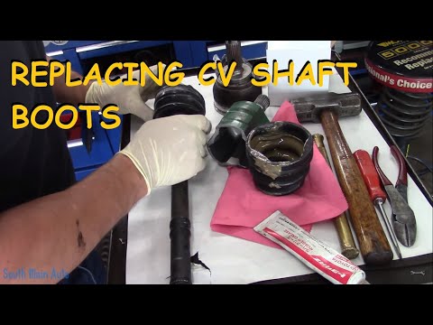
The constant velocity joint is a much more advanced mechanism. Its linearity is almost perfect, which results in smoother operation. As it is more complex, it is also much more expensive. Its design requires grease to lubricate it as well as to dissipate heat. A simple intrusion of water or sand into the assembly will contaminate the grease and inflict fatal punishment on the joint. As it is protected by a flexible bellow or boot, you can easily guess the importance of it being kept in good condition.
Periodic check of your half-axle boots
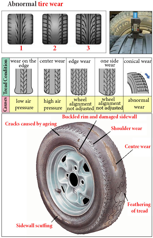
A simple visual inspection of the CV joint boots can tell you if you need to take action.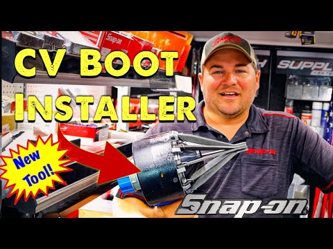 The presence of grease outside the boot indicates that immediate repair is needed. Traces of wear or cracks on the bellows are signs of repair intervention in a near future.
Choice of replacement boots
There are four choices of replacement CV boots on the market. That of the manufacturer of your ATV (OEM), the replacement “jobber” boot (aftermarket), the universal boot, and the replacement kit sold in two parts to be bonded together.
The latter is a real joke and I don’t recommend it. This replacement boot is split into two parts which must be assembled around the constant velocity joint and then bonded with glue. Cleanliness and very good dexterity are a must in this case. Repairing a CV boot with this kit is, indeed, really not as easy as it seems.
The third solution, the universal boot, can be interesting. This bellow does not require disassembly of the constant velocity joints. You have to stretch the boot and pass it over the joint. The boot composition is usually very flexible, but is also more fragile to the impact of branches and other objects encountered on the trails
The OEM and aftermarket replacement boots are, in my opinion, the best choices.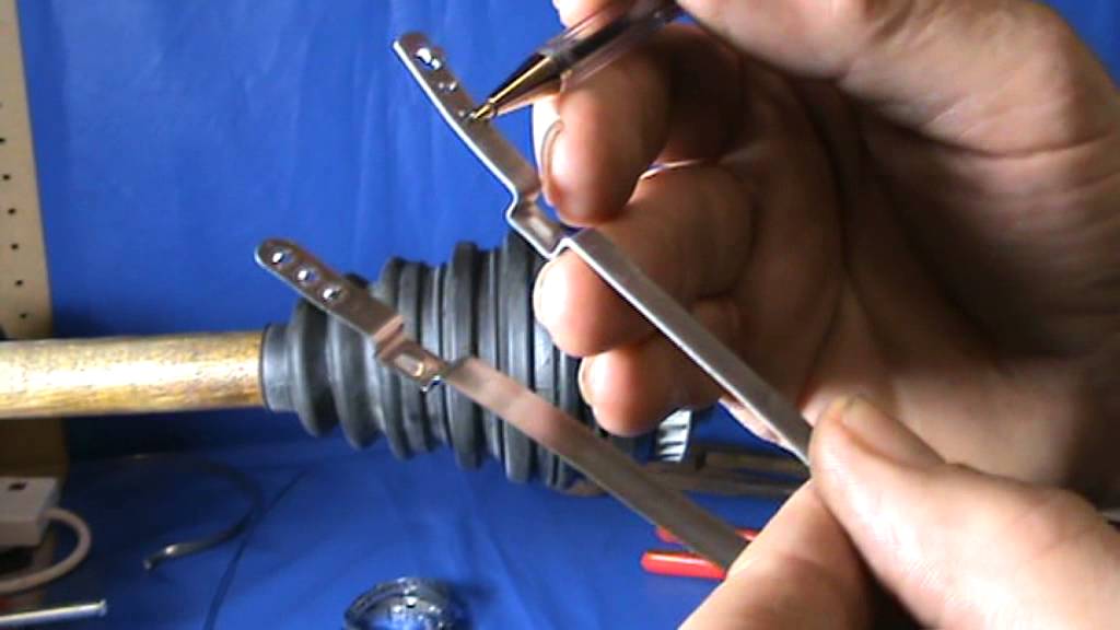 Those are the ones I recommend.
Replacement boot assembly
Replacing a half-axle boot
ATV used: CFMoto CForce 1000
Required tools
Removal of the wheel and disassembly of the brake caliper will be necessary. Unscrew the nut from the end of the half axle. Remove the retaining bolts from the ball joint suspension links on the steering knuckle. Release the assembly and set aside the knuckle.
Remove the half axle from the differential by pulling it firmly. It may be necessary to use a lever between the differential and the half-axle. Take care not to damage the differential seal.
Remove the clamps from the boot to be replaced using sharp wire cutters. Cut the old boot and set it aside. Inspect the grease in the CV joint. If the grease is not contaminated with water, sand, or dust, that is good news: the CV joint may still be in good condition.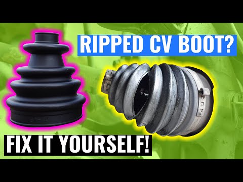 If, on the other hand, the grease is discolored or contaminated, the joint is likely damaged. In other words, even if the boot is replaced, a premature CV joint failure is to be expected.
To separate the CV joint from the half-axle, it will be necessary to use a hammer to hit it with a few light strokes. Use a brass punch and strike only in the central part near the half-axle. Note its installation position, it should not be reversed. Once the parts are separated, remove as much of the old grease as possible. Inspect the condition of the CV joint. If there are scratches or traces of abrasion, unfortunately, the joint will have to be replaced.
Damaged CV joint
Reassembly of the CV joint
First, put the small clamp on the half-axle. Then slip the CV boot. Pour some of the grease supplied with the replacement boot onto the constant velocity joint. Now reinstall the joint on the half axle. Make sure that it is properly locked in place. Pour the rest of the grease into the boot and put it in place over the CV joint. Install both clamps and tighten them using the boot clamp pliers.
CV Boot clamp pliers
Now you just have to reinstall the half-axle by reversing the procedure. Position the C-lock in the center of the half-axle, this will facilitate its insertion into the differential. If some oil has leaked out of the differential during repair, simply fill up the oil level. Make sure to respect the tightening torque of the wheel bearing nut.
In conclusion, a CV boot repair is a relatively simple operation. If there is any doubt as to the condition of your CV joint, it is possible to get a replacement unit without replacing the whole half-axle. However, in most cases, the cost of both parts (boot and CV joint), will exceed that of a full replacement half-axle assembly. Check the two options.
Corn stubble, rocks, wear and tear, whatever the cause, a torn CV boot if neglected, gets more expensive.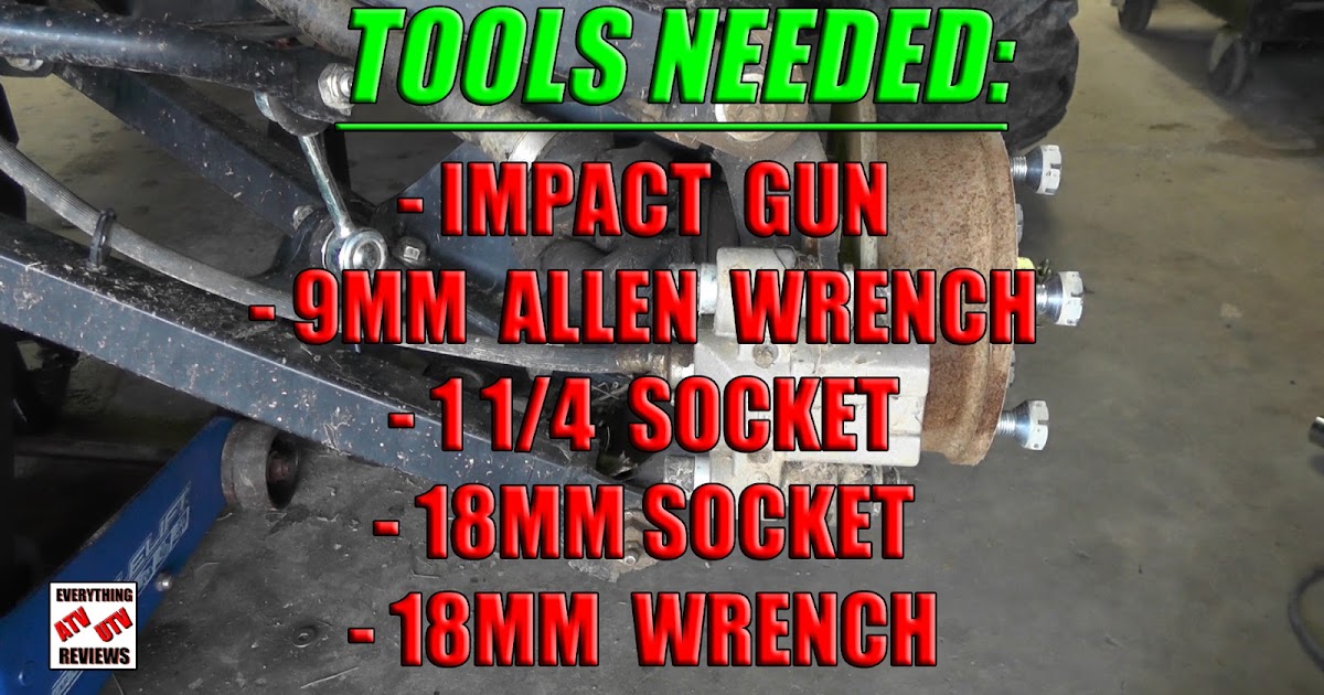 Always better to repair a torn boot asap; a worn half shaft is dangerous.
To repair a torn ATV CV boot, remove the following components in these eight steps:
1 Remove driveshaft
2 Remove old boot clamps
3 Remove outer CV joint and boot
4 Clean and inspect
5 Fit new clamps and boot
6 Refit CV joint
7 Pack with grease
8 Tighten boot clamps
In this post, you’ll learn how to replace an ATV CV boot, you’ll learn about the tools you’ll need and techniques required to nail the repair the first time.
Page Contents
Removing the driveshaft is necessary to fit a CV boot. Removing isn’t that difficult, and you won’t need any special tools. I wrote a whole post on the subject which you might find helpful, check out “ATV driveshaft removal. ”
”
The procedure requires the removal of the following components:
1 Wheel
2 Drive nut
3 Brake caliper
4 Steering arm
5 Upper ball-joint
6 Lower ball-joint
CV boots only last so long, so unless your boots are pretty new, I’d go ahead and replace both inner and outer. Boots, clamps, and grease aren’t expensive, but your time is valuable. You don’t want to revisit this corner of your ATV.
There are a couple of different type clamps employed, the reusable type and the one-time-only fit. Either way, you’ll have a new set with your new boots.
You’ll need a crimp tool to fit the one-time-use mushroomed type clamps.
CV joints (outer at wheel) are fixed to the shaft with either a hidden snap ring or a snap ring that needs squeeing. Inner joints are usually held in place with a circlip, however not all inner joints are removable.
Either way, both inner and outer boots can be replaced by removing just the outer CV joint.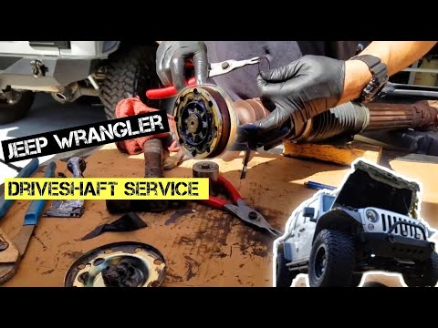
A hidden snap ring on the outer joint is most common.
Using a plastic hammer or a drift, sharply tap the inner CV splines ring, where it meets the shaft.
The CV joint will slide from the shaft and drop to the ground, so place some old packaging on the ground to break the fall. With the CV joint removed, you are free to slide the old boot off. If the inner boot needs to be replaced, go ahead and slide it off now too.
Clean as much of the old grease off as possible. A torn boot attracts grit and debris that will damage the CV joint. If your CV joint is noisy or has free-play, you’ll need to replace the CV joint or the whole half shaft.
With the old grease cleaned from the drive and joints, slid on the new boot(s) and clamps. We’ll need to keep the boots and joints mating surface grease-free.
Refitting the CV joint is easy. Just be sure you have all the boots and clamps assembled in the correct order. Pack the center of the CV joint with the CV boot grease (Molybdenum disulfide grease) supplied.
Position the CV joint in the vice with the CV joint side facing upwards. Position the shaft square over the CV joint end and strike the drive end with a plastic hammer (a metal hammer will damage the drive).
Pack additional grease into the boot(s). Clean the boot, and joint mating surface, grease on these surfaces may cause the boots to slip off. Position the boots in place.
Slide clamps onto boot collar and align centrally. Using your channel locks or crimping tool, tighten boot clamps. When tight, it won’t be possible to slide the clamp left or right.
That’s it, refit the half shaft. Job done!
You may find these posts helpful:
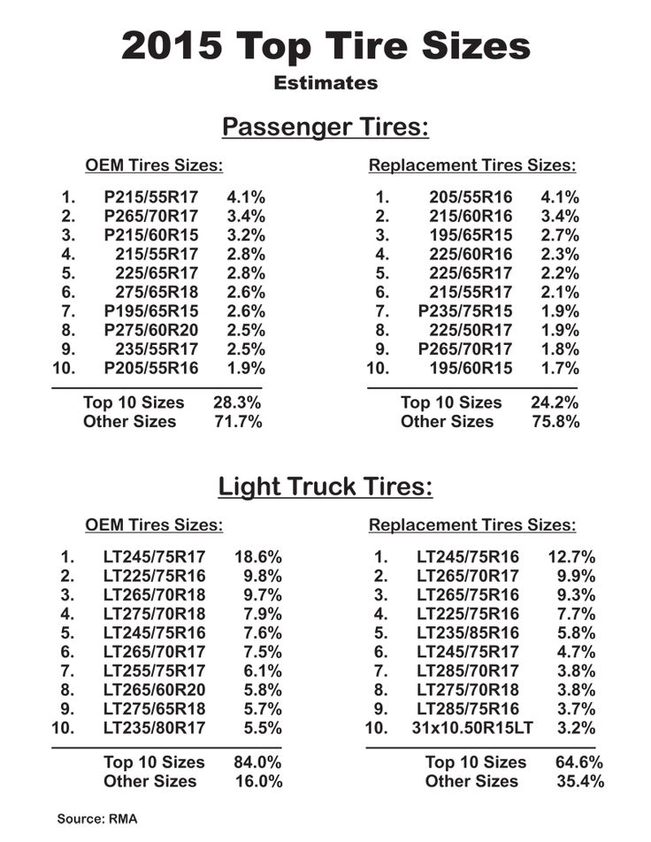
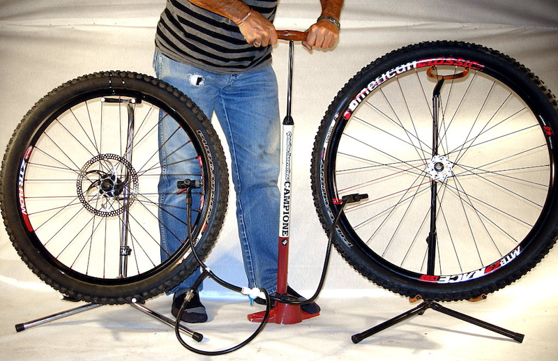
Does tire width matter?
How to check ball joints?
John Cunningham
John Cunningham is a technical writer here at ATVfixed.com. He’s a Red Seal Qualified Service Technician with over twenty-five years experience. He’s worked on all types of mechanical equipment, from cars and trucks to ATVs and Dirt bikes.
FID: 57, 60, 63, 68, 75, 76, 81, 82, 84, 127, 233, 234, 338
Module for reading and writing flash memory of engine control units Bosch gasoline vehicles made in China.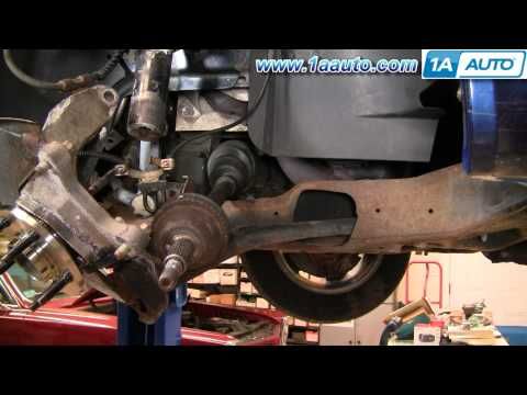
Bosch ME7.9.7 (FID: 68)
The Bosch ME7.9.7 control unit is based on a C167 processor with 1MB external flash memory. Supports virtual reading and writing, as well as correction of the COP.
Bosch M(E)7.9.71 (FID: 232)
The Bosch M(E)7.9.71 control unit is based on the ST10F275 processor with an internal flash memory of 832Kb. Supports virtual reading and writing, as well as correction of the COP.
Bosch M7.8 (FID: 57)
The Bosch M7.8 control unit is based on the ST10F275 processor with an internal working address space of 832Kb. Supports virtual reading, writing with disabling auto-protection, as well as correction of the COP.
Bosch ME7.8.8 K-line (FID: 63)
The Bosch M7.8.8 control unit is based on the ST10F275 processor with an internal working address space of 832Kb. It supports virtual reading, writing with disabling auto-protection via the K-line, as well as correction of the COP.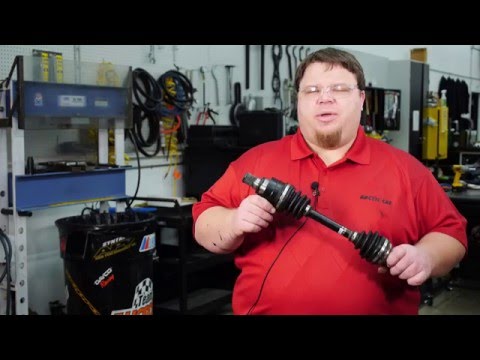
Bosch ME7.8.8 CAN (FID: 76)
The Bosch M7.8.8 control unit is based on the ST10F275 processor with an internal working address space of 832Kb. It supports virtual reading, writing with auto-protection disabled via the CAN bus, as well as correction of the COP.
Bosch ME17.8.8 (FID: 60)
Bosch ME17.8.8 control unit is based on Infineon Tricore TC1728 processor with 1.5Mb internal flash memory. Reading and writing of the calibration area is supported, as well as correction of the COP.
Bosch ME17.8.8 Saic (FID: 127)
For Saic vehicles. The Bosch ME17.8.8 control unit is based on the Infineon Tricore TC1728 processor with an internal flash memory of 1.5 MB. Reading and writing of the calibration area is supported, as well as correction of the COP.
Bosch ME17.8.8 Vantage (FID: 166)
For Vantage vehicles. The Bosch ME17.8.8 control unit is based on the Infineon Tricore TC1728 processor with an internal flash memory of 1. 5 MB. Reading and writing of the calibration area is supported, as well as correction of the COP.
Bosch ME17.8.8.1 (FID: 82)
The Bosch ME17.8.8.1 control unit is based on the Infineon Tricore TC1728 processor with an internal flash memory of 1.5 MB. Reading and writing of the calibration area is supported, as well as correction of the COP.
Bosch ME17.8.8.1 Geely (FID: 84)
For Geely vehicles. The Bosch ME17.8.8.1 control unit is based on the Infineon Tricore TC1728 processor with an internal flash memory of 1.5 MB. Reading and writing of the calibration area is supported, as well as correction of the COP.
Bosch MED17.8.10 Haval (FID: 122) /TEST/
For Haval vehicles. The Bosch MED17.8.10 control unit is based on the Infineon Tricore TC1728 processor with an internal flash memory of 1.5 MB. Reading on the table and writing through the diagnostic connector are supported, as well as correction of the COP.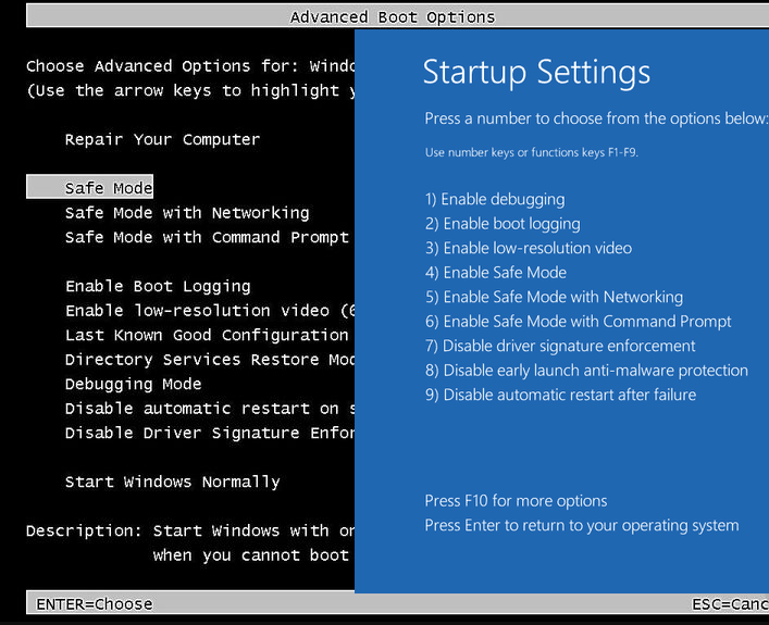
Bosch MED17.8.10 Geely (FID: 234) /TEST/
For Geely vehicles. The Bosch MED17.8.10 control unit is based on the Infineon Tricore TC1728 processor with an internal flash memory of 1.5 MB. Reading on the table and writing through the diagnostic connector are supported, as well as correction of the COP.
Bosch MED17.8.10 Chery (FID: 338)
For Chery vehicles. The Bosch MED17.8.10 control unit is based on the Infineon Tricore TC1782 processor with an internal flash memory of 2.5 MB. Reading and writing through the diagnostic connector is supported, as well as correction of the COP.
BYD TB10 Type1 (FID: 81)
The BYD TB10 control unit is based on the Renesas SH72531 processor with 1.25MB internal flash memory. Reading and writing of the calibration area is supported, as well as correction of the COP.
BYD TB10 Type2 (FID: 148)
The BYD TB10 control unit is based on the Renesas SH72531 processor with 1.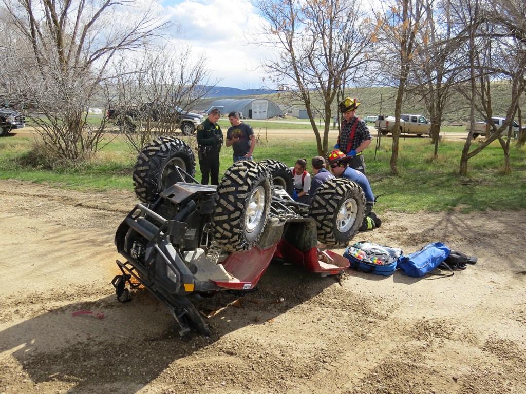 25MB internal flash memory. Virtual reading and writing of the calibration area is supported, as well as correction of the COP.
Bosch M7.8/ME7.8.8 BSL K-line (FID: 75)
Allows reading Bosch M7.8/ME7.8.8 K-line units based on ST10F27X secure processors in BSL mode. Requires BITS001 adapter. Guaranteed to only work with Tactrix Openport 2.0 adapter
Updated windows
If after installing a second OS, trying to take advantage of free space on hidden disk partitions or formatting them, in case of system failures, when experimenting with EasyBCD and in other cases, you are faced with that Windows 10 won't boot, reporting "An operating system wasn't found", "No bootable device found. Insert boot disk and press any key", then you may need to restore the Windows 10 bootloader, which will be discussed below.
Regardless of whether you have UEFI or BIOS, whether the system is installed on a GPT disk with a hidden FAT32 boot EFI partition, or on an MBR with a System Reserved partition, the recovery steps will be the same for most situations.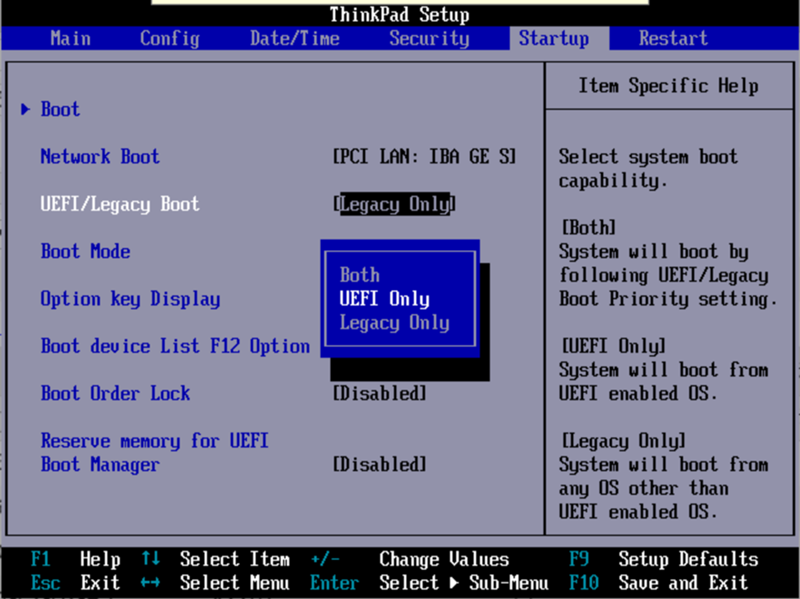 If none of the below helps, try Resetting Windows 10 and Keeping Data (Third Method). Note: errors like the ones above are not necessarily caused by a corrupt OS loader. The reason may be an inserted CD or a connected USB drive (try removing it), a new additional hard drive, or problems with your existing hard drive (first of all, see if it is visible in the BIOS).
The Windows 10 Recovery Environment offers a Startup Repair option that works surprisingly well and is sufficient in most cases (but not always). To restore the bootloader in this way, follow these steps.
Upon completion, you will either see a message stating that the recovery failed, or the computer will automatically reboot (do not forget to return the boot from the hard drive to the BIOS) already in the restored system (but not always).
If the described method did not help to solve the problem, we move on to a more efficient, manual method.
To restore the bootloader, you will need either a Windows 10 distribution (bootable USB flash drive or disc) or a Windows 10 recovery disc. If you do not have these, you will have to use another computer to create them. You can read more about how to make a recovery disc in the article Restore Windows 10.
The next step is to boot from the specified media by setting the boot from it to BIOS (UEFI), or using the Boot Menu. After booting, if it is an installation flash drive or disk, on the language selection screen, press the Shift + F10 or Shift + Fn + F10 keys on some laptops (a command prompt will open). If this is a recovery drive, select Diagnostics - Advanced Options - Command Prompt from the menu.
In the command line, enter three commands in order (after each press Enter):
As a result of executing the command list volume , you will see a list of mounted volumes. Remember the letter of the volume on which the Windows 10 files are located (during the recovery process, this may not be partition C, but a partition under some other letter).
In most cases (there is only one Windows 10 operating system on the computer, a hidden EFI or MBR partition is available), in order to restore the bootloader, it is enough to execute one command after that:
bcdboot C:\windows (where you may need to specify a different letter instead of C, as mentioned above).
Note: if your computer has several operating systems, for example, Windows 10 and 8.1, you can run this command twice, in the first case specifying the path to the files of one OS, in the second - another (will not work for Linux and XP. For 7-ki configuration dependent).
After running this command, you will see a message that the download files were created successfully. You can try restarting the computer in normal mode (by removing the bootable USB flash drive or disk) and check if the system boots (after some failures, the boot does not occur immediately after the bootloader is restored, but after checking the HDD or SSD and rebooting, error 0xc0000001 may also appear, which in this case is also usually fixed by a simple reboot).
If the above method did not work, then return to the command line in the same way as we did before. We enter the commands diskpart , and then - list volume . And we study the connected disk partitions.
If you have a system with UEFI and GPT, in the list you should see a hidden partition with the FAT32 file system and a size of 99-300 MB. If the BIOS and MBR, then a 500 MB partition (after a clean installation of Windows 10) or less with the NTFS file system should be detected. You need the number of this section N (Volume 0, Volume 1, etc.). Also note the letter corresponding to the partition where the Windows files are stored.
Enter the following commands in order:

Upon completion, close the command prompt and restart the computer no longer from an external boot drive, check if Windows 10 boots.
I hope this information will help you. By the way, you can also try "Startup Repair" in the advanced boot options or from the Windows 10 recovery disk. Unfortunately, everything does not always go smoothly, and the problem is easily solved: often (in the absence of HDD damage, which can also be) you have to resort to to reinstall the OS. Also, to restore, you can try a simple command bootrec.