Home - Dirtbike - Dirtbike Features - ATV Electronics series: Part 1 - ignition systems
Few things can be as frustrating as diagnosing electrical systems. After all, there are seldom obvious signs of failure - I mean, you just can't see if electrons are flowing or not. Sure, every now and then you find a corroded connection, frayed wire, or burn looking electrical thingamajig. But how can you tell if your CDI or stator is bad? It's a real drag to have spent $100 or more on a new coil only to find that your safety tether had a bad connection.
The key to effectively troubleshooting electrical systems is to have a solid understand of their operation. Only then can one efficiently narrow down what the faulty component is. To aid in that process, the technical folks at ORC have decided to put together a three-part "electrical systems" series to cover the three most basic systems of the typical ATV: ignition, charging, and starting. To kick off the series, the first installment handles the most important: ignition.
Of course, the primary purpose of the ignition system is to create a spark. Years ago, a fellow named Kettering came up with a pretty good way to make a spark. Very basically, his invention consisted of two sets of finely wound copper wire - commonly referred to as the ignition "coil" -.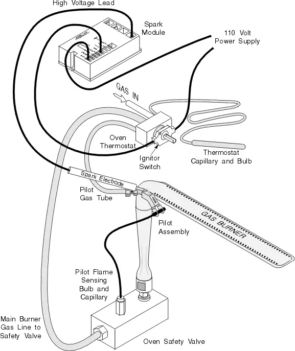 that when powered with electricity on one winding would create a sudden jolt, or spark, of electricity on the other when the electrical power is interrupted. To keep up with a spinning engine, the electrical power is switched on and off via a contact switch that's controlled by a cam lobe driven by the engine. Pretty darn simple, and pretty darn easy to diagnose with basic tools. However, this conventional "breaker" or points-type ignition had reliability issues and was limited to low rpm applications. Enter the age of high tech electronics: integrated circuits, transistorized ignitions, and CDI...
The good news is that CDI, or capacitor discharge ignition, was all that points-type ignitions weren't - they had no moving or wearing parts, could produce a heck of a spark, and could run very high speed. Bad news is that the ignition system now became a "black box", both literally and metaphorically. No spark? Might as well start swapping parts until you the spark magically reappears. Not a bad proposition for a dealer that has parts sitting on the shelf he can try with no obligation. But to spend a hundred non-refundable dollars on simply a hunch is a tough pill to swallow.
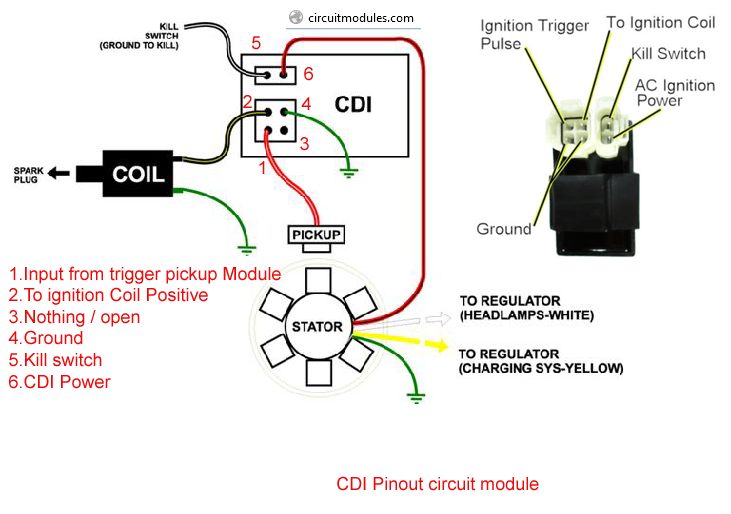
| Schematic of a typical CDI ignition system |
Fortunately, we can break down the operation of the CDI to some basic circuits - the guzzinta's and the guzzouta's (inputs and outputs).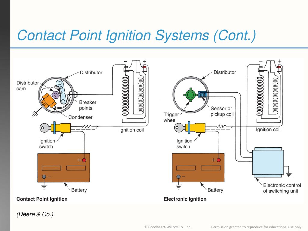 Whereas the points-type ignition has only two circuits (power and ground), the CDI has 5 primary circuits. On the guzzinta side we have the obligatory duo of power and ground, but with the added complexity of a circuit to tell the CDI when to fire (trigger circuit), and another to tell if to fire (kill circuit). What's left is the only circuit on the guzzouta side: the power to the ignition coil (fire circuit).
So let's discuss those circuits and their possible failure modes. The CDI's ground (DC negative) is always connected and provides the connection back to the engine's own voltage ground point or reference, which is the same reference the spark plug uses when creating a spark. The key piece of info here is that wherever the CDI makes its ground connection has to be essentially the same ground reference as the spark plug - make sure there's clean metal all the way between the two connection points, and virtually no resistance (ohms).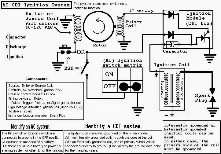 If the CDI makes its ground connection at the frame up near the gas tank, be assured that the circuit from there is good all the way back the cylinder head. Don't rely on a ground connection through engine mounts. They can be intermittent, dirty, corroded, rubber-bushed, or painted. Proper grounding would dictate a ground strap from the engine directly to the wire harness.
Next thing we need is a way to power the CDI. Some CDI's are powered by 12vdc from the machine's electrical system, but most others generate the requisite electrical power from an exciter coil underneath the flywheel. As the magnet on the flywheel passes the exciter coil, electrical current is generated and in the case of a Capacitor Discharge Ignition or CDI, that charge is stored temporarily in a capacitor for a split second until the CDI is told to fire. Since the CDI is already tied to ground, there's only a single wire connecting the exciter coil to the CDI. To check this voltage produced by the exciter is tricky because it requires the engine to be turning. An electric starter can produce the necessary crank rotation, but diagnosis by means of kick starting is difficult since the output voltage varies with engine speed. To check, use a digital voltmeter (DVM) and set to AC scale. Connect one DVM lead to the exciter output wire, and the other to case ground. Most shop manuals will list a minimum AC voltage for both running and starting. Be CAREFUL when testing, the output from the exciter coil can reach 200 volts!
The power stored in the CDI's internal capacitor needs to be put to work, but the key to proper engine performance is doing it at the right time.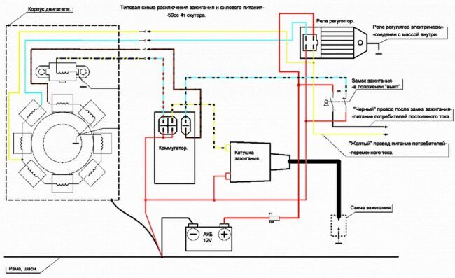 That's where the pulse generator comes into play. Again, underneath the flywheel lies yet another magnet and coil combo, but the sole purpose of these two is to precisely identify to the CDI the position of the crankshaft. That is, it tells the brain box where the piston is and therefore when to fire. Basically, the CDI waits around for the pulse generator to tell it that the piston has just hit some point before TDC, and then waits the appropriate amount of time (dependent on rpm and spark advance) before energizing the guzzouta circuit that sends power to the well-recognized ignition coil. This circuit is diagnosed similarly to the exciter coil above, but instead connect your DVM to the pulse generator output. The voltage is much less and should be listed in your manual.
The last CDI circuit is the "kill circuit" which is how the CDI knows to quench the spark and kill the engine. Typically this circuit is switched to ground, and some CDI's require this circuit to be closed, while others require it to be open for engine shutdown. Most safety tethers, kill switches, and ignition switches utilize this circuit to control engine operation. The easiest way to troubleshoot a no-spark malfunction is to pull the spark plug and check for spark by unplugging this circuit. If no spark, then connect a ground wire directly between engine ground and this circuit (on the CDI box side). If still no spark, the problem is likely with another circuit.
To complete the whole ignition system, we still need to produce enough voltage to jump a spark across a 1mm gap, inside a running engine.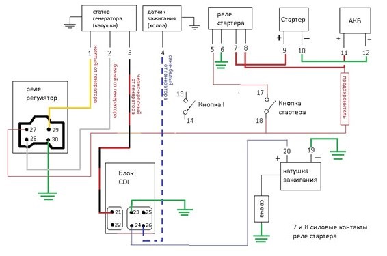 This part of the system hasn't changed much over the years - it's still a good ole ignition coil with a small wire going in, and fat one going out. It's a little different since we no longer have 12vdc going in, but rather nearly 10x that!. It also requires a good ground connection so insure that there's no corrosion, mud, or paint separating the mating connections. Although it's easy to blame coils for electrical problems since it's difficult to test (resistance checks are not always reliable), they are not commonly known to be failure prone. More likely is a bad spark plug cap or connection to the fat plug wire. With some coils passing as much as 60,000 volts make sure your plug wire and cap has no exposed breaks or possible leak paths that water can penetrate.
 When the coil fires it will seek the path of least resistance, and if there's a way for 60,000 volts to get to ground easier than through a compressed air-fuel mixture (spark plug gap), it'll take it. And water does that job quite nicely.
Stay tuned, next month we'll get into the charging system of an ATV's electrical system.
Systems: Electrical
Commonly Located: The ignition coil is generally located on the upper portion of the frame, near the top of the engine. It can commonly be found above the radiator.
Physical Description: The ignition coil is normally a squarish shape with one to three smaller wires leading into the wiring harness and one larger wire leading to the spark plug. While some ignition coils have a removable spark plug wire, most do not. The wire leading to the spark plug is covered by a thick rubber boot. The spark plug wire boot is usually a separate piece that can be replaced independent of the ignition coil.
Function: When the engine is at top dead center, the pickup coil signals the ignition coil to send a high voltage pulse to the spark plug. The spark plug wire boot ensures that none of this energy escapes on it's way to the spark plug. This high voltage pulse is what causes the spark that ignites the air and fuel mixture in the cylinder.
Maintenance Costs: The ATV ignition coil is a common wear item; therefore, it is not recommended to purchase a used coil as a replacement.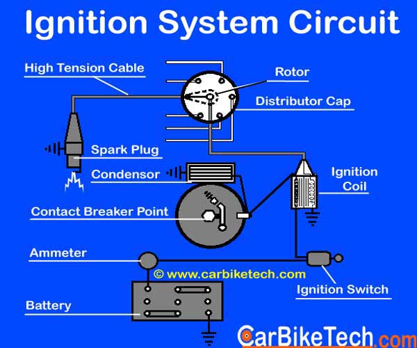 Fortunately, the ignition coil is relatively inexpensive.
Filed in: Anatomy of an ATV
Share: Previous article A Look at The BEST ATV Service ManualOriginal price $ 159.99 - Original price $ 159.99
Original price
$ 159.99
$ 159.99 - $ 159.99
Current price $ 159.99
| /
Original price $ 129.99 - Original price $ 159. 99
99
Original price
$ 129.99 - $ 159.99
$ 129.99 - $ 159.99
Current price $ 129.99
| /
Original price $ 40.00 - Original price $ 40.00
Original price
$ 40.00
$ 40.00 - $ 40.00
Current price $ 40.00
| /
View all ODES UTV Performance mods
ODES UTVS best sellers See more
Original price $ 38.49 - Original price $ 55.99
Original price
$ 38.49 - $ 55.99
$ 38.49 - $ 55.99
Current price $ 38.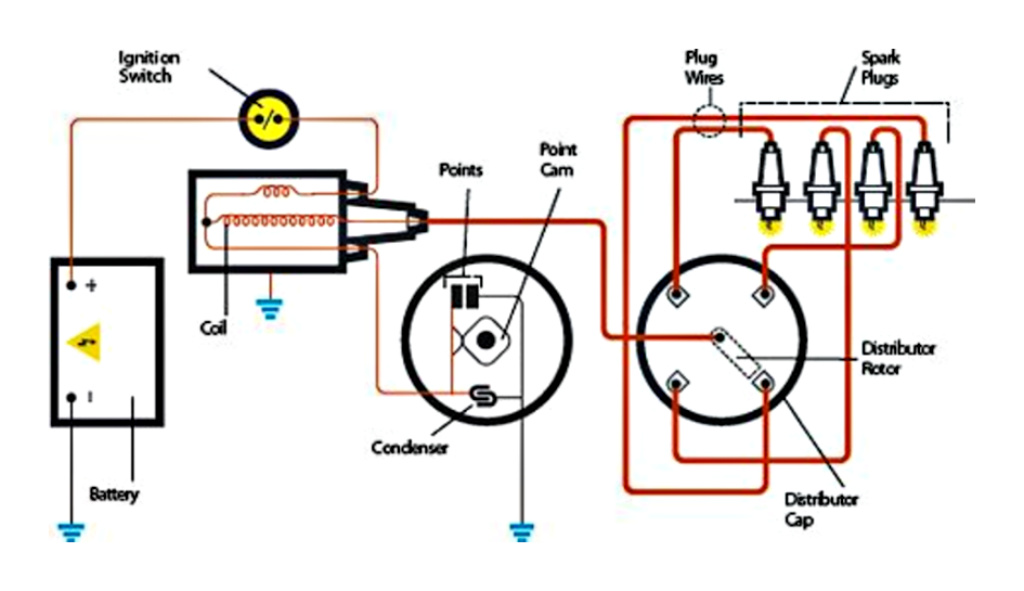 49
49
| /
Original price $ 7.99 - Original price $ 7.99
Original price
$ 7.99
$ 7.99 - $ 7.99
Current price $ 7.99
| /
Original price $ 49.99 - Original price $ 62.00
Original price
$ 49.99 - $ 62.00
$ 49.99 - $ 62.00
Current price $ 49.99
| /
Original price $ 159. 99 - Original price $ 159.99
Original price
$ 159.99
$ 159.99 - $ 159.99
Current price $ 159.99
| /
Original price $ 18.99 - Original price $ 18.99
Original price
$ 18.99
$ 18.99 - $ 18.99
Current price $ 18.99
| /
Original price $ 29.99 - Original price $ 29.99
Original price
$ 29. 99
99
$ 29.99 - $ 29.99
Current price $ 29.99
| /
Original price $ 414.99
Original price $ 414.99 - Original price $ 414.99
Original price $ 414.99
Current price $ 385.99
$ 385.99 - $ 385.99
Current price $ 385.99
| /
Save 7% Save %
October 8, 2022
Read nowSeptember 16, 2022
Read nowAugust 30, 2022
Read now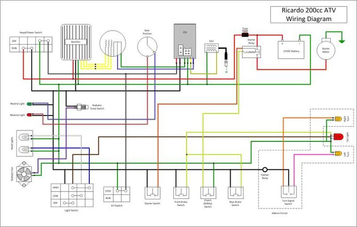 rf - a project dedicated to the universal ignition system for ATVs
 Almost all carburetor engines of ATVs and motorcycles are traditionally equipped with a CDI (Capacitor Discharge Ignition) ignition system. In this system, energy is stored in a capacitor and at the right moment it is discharged through the primary winding of the ignition coil, which is a step-up transformer. A high voltage is induced in the secondary winding, which breaks through the gap between the electrodes of the spark plug, forming an electric arc that ignites the mixture of gasoline and air.
To synchronize the ignition operation, an induction crankshaft position sensor is used - DPK, which is a coil wound on a permanent magnet core:
The mark is the tide on the iron housing of the generator rotor (popularly called the flywheel): sensor core , it changes the magnetic flux through the coil , thereby inducing a voltage across the coil 's terminals . The waveform is as follows:
i. e. two pulses of different polarity. On almost all engines, the polarity of switching on the sensor is such that the first is a positive pulse corresponding to the beginning of the tide, and the second negative - the end of the tide. For normal engine operation, ignition must occur a little earlier than top dead center - TDC, so that the maximum pressure of the combustion products reaches just at TDC. This “slightly earlier” is commonly called the Ignition Advance Angle - UOZ and is measured in degrees, which are left to turn the crankshaft to TDC. When starting the engine, the UOZ should be minimal, and with an increase in speed, it should increase. As mentioned above, the WPC produces two synchronization pulses - the beginning of the tide and the end of the tide. In simple (not microprocessor) CDI systems, the end of the tide corresponds to the pre-set UOZ - this signal ignites when the engine is started and at idle. The onset of the tide corresponds to the SPD at high speeds. Most often in such systems, the end of the tide is set to 10-15 degrees ahead, and the “length” of the tide is from 20 to 30 degrees.
At the same time, advanced CDI units smoothly change the moment of sparking from the “end of the tide” to the “beginning of the tide” in the range from 2000 rpm to 4000 rpm, while the cheap ones simply jump to the beginning of the tide with increasing speed. In CDI microprocessor systems, the length of the tide is much longer - from 40 to 70 degrees, while its end, as before, corresponds to the preset UOZ, and the beginning is the starting point for the microprocessor, which, depending on the speed, sets the desired UOZ.
In different engines, the “length” of the tide is different, therefore CDI blocks, even with the same connectors, are most often not interchangeable!
It should also be added that high voltage is needed to power the CDI units, because. the time of energy accumulation in the capacitor is limited; its capacity is taken small and it is charged with a high voltage - several hundred volts. For this, in simple systems, the generator has an additional high-voltage winding. The power of this winding is small, so the spark in such systems at engine start is weak, which makes winter operation difficult. To avoid this problem, so-called DC-CDIs are used, in which the capacitor is charged from a battery-powered boost converter. In such systems, the power of the spark does not depend on the speed and starting the engine in cold weather is much easier.
Now for the disadvantages of CDI ignition. The most important disadvantage, which cannot be eliminated for little money, is a very “weak” “short” spark. It is impossible to build a powerful CDI system without significant material costs.
For example, CDI for domestically developed car engines cost more than a thousand dollars, and imported ones, which are installed on racing cars with high-speed engines, can cost more than one thousand.
The larger the volume of the cylinder in the engine, the stronger the effect of the lack of spark energy. This is expressed in incomplete combustion of fuel, loss of power, very high fuel consumption. When CDI first appeared, it was put on mopeds, motorcycles, most often the engine size of which was 50 cubes. Such a small amount of air-fuel mixture was easily burned out by a weak CDI spark. With the increase in cubic capacity, it became clear that something needed to be changed and DC-CDI appeared. But the cubic capacity continued to grow, and with it the amount of gasoline that literally flew into the pipe grew. They even came up with systems that burn gasoline in the exhaust pipe! :O) I don’t understand what the manufacturers of motorcycles were thinking all this time, because at the same time, a different ignition system was used on cars for a long time, with the accumulation of energy in an inductor, which made it possible to get hundreds of times more spark power for the same money and solve everything ignition problems. Of course, CDI is no longer installed on the injection engines of modern motorcycles. But this is a drop in the ocean! Today the picture is that 90 percent of motorcycles and ATVs continue to eat gasoline and spit it out into the atmosphere.
It would seem that everything is very simple - it is necessary to change the ignition for all to a more perfect one, but there are a few BUT! If it's CDI, then it turns out very expensive. If it is IDI, as in injection systems, then for its operation it is necessary to change the generator rotor, which is even more expensive. (for correct control of the coil operating modes in the IDI system, one mark on the flywheel is not enough, several dozen short marks are used - in fact, a gear wheel with synchronization by a missed tooth) All this is true if we solve the problem head-on. But if you think a little, apply a powerful microprocessor and show ingenuity, it turns out that not everything is so bad!
BACK!
ATTENTION!!! DO NOT SWITCH ON THE IGNITION WITHOUT THE HIGH WIRE, THE PLUG, OR IF THE PLUG IS NOT TWISTED INTO ITS PLACE OR IS NOT RELIABLELY EARTHED TO THE ENGINE BODY!!!
A SCRETTER WILL COME TO THE COIL WITH A PROBABILITY OF MORE THAN 50 PERCENT!!!
IN THIS COIL, A BREAKDOWN OCCURRED INSIDE THE COIL AND A INTERTURN FAULT MAY APPEAR!!! THE PRESENCE OF THE INTERTURN CLOSURE OFTEN DOES NOT INTERFERE TO WORK AND THE SPARK IS PRESENT, BUT NOT FOR LONG - AT THE END OF THE END THE COIL DIES AT ALL.
To connect the ignition control unit (BUZ) to the ATV's on-board network (only connector 1 is used), disconnect the standard CDI unit from its connector (on some models, the standard unit is not disconnected, see clarifications in the descriptions) or disconnect the DPK connector, disconnect the BB wire of the standard ignition coil from the spark plug, to the “signal” wire (most often it is a blue or white-blue wire) of the DPK, connect the input of the BUZ (blue wire) ,)
the DPK wire (let's call it "-" DPK) (most often green) is connected to ground (sometimes it is connected to ground only in the CDI unit, sometimes directly in the generator itself, if not, we connect it to the "-" battery, the yellow wire of the BUZ to + Battery after the ignition switch (most often it is a black wire), white wire to the “-” terminal of the ignition coil, Terminal “+” of the ignition coil through a 15 amp fuse to + battery, BB wire to the coil and spark plug.
Everything, you can start. As wound up, you should adjust the speed of the twentieth.
To return to the standard ignition system: disconnect the connector 1 BUZ, the standard CDI unit back into its place, the BB wire from the standard coil to the spark plug.
Connector number 2 is optional, add. functions are activated by shorting the desired wire to MASS !!! If they are not needed, insert a chip into the connector anyway so that WATER does not get in !!! it is necessary !!!
There are a few things to pay attention to when installing and starting the system. Here is a list of what caused the ignition to work poorly on different quadrics: