Today's Featured Article - Bad Vibes - by Curtis Von Fange. Latest Ad: I H model 314 fast hitch roll over plow, large shares all new wear parts, 16 inch bottoms, calls only 330-831-8547 [More Ads]
| |||||
Today's Featured Article - Bad Vibes - by Curtis Von Fange. One of the strangest ways to communicate with our tractor is to ask it how it feels. "Ask it how it feels," you say? Yup, ask it how it feels. Now, as with the other articles in this series one has to be able to hear what 'ole blue' is trying to say in response. The nice thing about our old iron friends is that they are usually quite consistent in their response, rather unlike some people I know who might change what they say due to the weather or other mitigating circumstances. Latest Ad: I H model 314 fast hitch roll over plow, large shares all new wear parts, 16 inch bottoms, calls only 330-831-8547 [More Ads]
| |||||
Tractor undercarriage maintenance
Pneumatic tire maintenance. Pneumatic tires, if not used correctly, quickly become unusable. It is especially important for safety to maintain the necessary air pressure in them.
Tire maintenance includes: visual inspection, maintenance of the desired internal air pressure and control of the height of the lugs, the dimensions of which are used to judge the maximum wear of the tire.
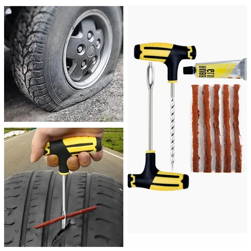
Exterior tire inspection.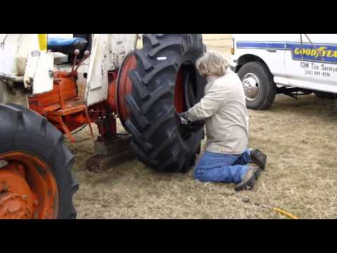 Carefully inspect the tires every day and immediately remove all solid objects found in the tread: nails, glass, stones, etc. In case of through damage, it is necessary to send the tires for repair.
Checking the air pressure in the tires is the most important operation that affects the durability of the tire and its grip on the ground.
When the tire is operated with reduced air pressure, the middle part of the tread (fig. 82, a) is somewhat unloaded, bending inside the tire, which increases the stress of the material in the extreme zones of the tread. Over time, the cords of the inner layer peel off from the rubber, which leads to their fraying and tearing.
Lower pressure operation reduces lugs contact with the ground, which in turn increases treadmill edge slip and wear while leaving the middle section nearly unworn.
Increased air pressure reduces tire deformation (Fig.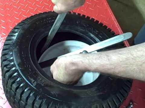 82.6) and, accordingly, its contact area with the road. As a result, wear of the tread (leash lugs) in its middle zone is accelerated and wheel slippage increases.
Fig. 82. Scheme of immersion in the soil of the tractor tires' lugs at different internal air pressure:
a - insufficient; b - excess; in - normal.
In addition, the tension in the carcass cord threads increases, which accelerates the process of cord “fatigue” and leads to premature carcass rupture.
When the air pressure in the tire meets the manufacturer's recommendations, the lugs enter the soil more evenly (Fig. 82, c), the tires wear more evenly and more slowly, which greatly increases their service life.
To check the pressure, clean the valve from dirt, unscrew and remove the cap. Press the tip of a tire pressure gauge against the valve and read the tire pressure. If it does not correspond to the norm, then bring it to the desired one.
It should be remembered that tire pressure is not the same for different types of work and also depends on the implements with which the tractor is working.
For this purpose, place the tractor with the implement on the balance as shown in Figure 83. Determine the gravity of the tractor, first on the rear wheels, and then (after the tractor has been moved) on the front wheels. Divide the results by 2 to get the pressure per wheel.
Determining the wear of the lugs and ribs of pneumatic tires. To determine the wear of the pattern or lugs of the tread of a pneumatic tire, clean the tread from dust and dirt. Then inspect the treadmill and identify by eye the place with the greatest wear, where you should draw a platform in chalk on which you will need to measure.
Fig. 83. Tractor weighing on car scales:
1 - scales; 2 - tractor.
Fig. 84. Determination of tire lugs wear:
a and d - measuring points; b - measurement with a caliper; c - measurement with a device; 1 - depth gauge; 2 - fixture.
Using a depth gauge (fig. 84.6), providing an accuracy of ± 0.1 mm, or a special device (fig. 84, c), measure the areas of greatest wear, except for the locations of half-bridges or ledges at the base of the tread pattern.
Measure the height of the lugs in the center (fig. 84, d) or in places the least distant from the center of the treadmill, but not along the ledges at the base of the lugs and not along the half-bridges.
In the event that the tractor will operate at a speed of less than 30 km/h, the load on the tires can be increased to the values indicated in table 29.
The wear limit of the lugs, after which the tire must be removed from the tractor and sent for repair, will be wear of more than 80%. In this case, the slipping of the driving wheels increases to 20...28%, the performance decreases by 10...12% and fuel consumption increases by 6...8%.
After determining the wear of the lugs, compare the wear of the tires of the right and left wheels (the difference is no more than 6%). Otherwise, this can lead to misalignment and deformation of the axle shafts and wheel disks, as well as violation of the front wheel alignment angles. These deviations should be identified and corrected.
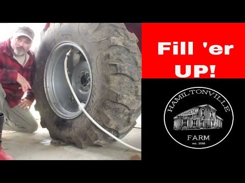
Tractor wheel chambers are filled with fluid to increase traction.
Fill up 3/4 of the chamber with clean water in summer. At ambient temperatures below +5 °C, use a solution consisting of 25 parts (by weight) of calcium chloride (CaCl) and 75 parts of water. Such a solution has a freezing point down to -32 ° C.
If you pour liquid, for example, into a wheel size 12-38 by 3/4 of the volume, then its grip will increase by 1700 N.
To pour liquid into the chamber, you need to raise the wheel (Fig. 85, a) with a jack until it is off the ground, connect the tip of the device with an air valve and, having opened the liquid access, fill the chamber. After that, air should be pumped into the tire to the required pressure.
To remove liquid from the chamber, it is necessary to put the valve in the lower position, remove the spool and drain the main part of the liquid. The rest of the liquid can be removed as follows: pump air into the tire to a pressure of 0.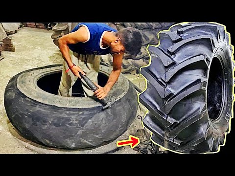 1 ... 0.15 MPa, remove the sleeve with the spool from the valve and insert a tube with a rubber seal into valve 2 (Fig. 85.6) in their place. The fluid will then be squeezed out by the internal air pressure in the tire.
Fig. 85. Increasing the coupling force of the tractor:
a - filling the chambers of the driving wheels of the tractor; b - removal of liquid from the chamber; 1 - rubber seal; 2 - valve; 3 - tube.
Fig. 87. Putting on and removing tires from the rim:
a, b, c, d, e and f - the sequence of operations.
Installation of dual drive wheels. During the operation of the tractor on waterlogged soils and reclaimed peatlands, it is advisable to install dual wheels to reduce the slippage of the driving wheels of the tractor.
As an example, figure 86 shows the connection of dual wheels on the MTZ-80 and MTZ-100 tractors. Wheels should be installed so that the bulges of the discs are located against the spacers.
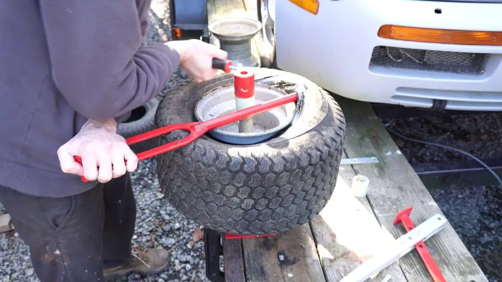
Putting tires on and off the rim. Thoroughly clean the wheel rim from dirt and corrosion and determine which side of the tire should be put on the rim so that after putting the finished wheel on the tractor, the direction of its rotation coincides with the arrow on the tire (Fig. 87, a).
Insert one tire bead through the rim flange by first putting part of the bead on the rim, then using the spatulas to pull the entire bead.
Powder a dry, clean chamber with a thin layer of talcum powder, place it in the tire (fig. 87.6), straighten it carefully, and insert the valve into the hole in the rim.
Fig. 86. Installation of dual driving wheels of the MTZ-80 tractor: 1 - disks; 2 - spacer.
Insert part of the second tire bead from the side opposite to the valve (Fig. 87, c), and, following the correct position of the valve with the help of spatulas, pull the rest of the tire bead. Finish pulling at the valve (Fig. 87, d).
Inflate the tire with air to a pressure exceeding the norm by 50 .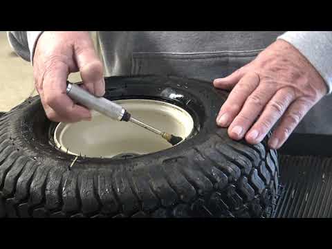 .. 100 kPa so that the tire fits well on the rim, and then reduce the air pressure through the spool to the norm.
To remove the tire, bleed the air out of the chamber by unscrewing the spool from the valve.
Slide both tire beads off the rim flanges into the rim recess on the side opposite the valve.
Insert two mounting spatulas between the tire bead and the rim on both sides of the valve at a distance of 10 cm and drag over the rim flange first part of the bead at the valve (Fig. 87, e), and then the entire bead.
Push the valve inside the rim and then remove the tube from the tire. Turn the wheel over 180 °, move the tire bead rim recesses to one side, and on the other side, insert the blades and remove the rim from the tire (Fig. 87, e).
Checking and adjusting the front wheel bearings of multi-crop tractors. Brake the rear wheels of the tractor with the parking (mountain) brake and raise the front wheel with a jack until it does not touch the ground.
Attach the indicator head to the front wheel trunnion so that its shaft is in contact with the surface of the wheel hub, and set the dial to zero in the opposite direction of the arrow. By moving the wheel along the axis of the trunnion with your hands, determine the clearance in the bearings. The maximum allowable clearance in the bearings is 0.25 mm.
Fig. 88. Checking the bearings of the front wheels (a) and adjusting the guide (b) and drive (c) wheels:
1 - nut; 2 - cap; 3 - gear; 4 - cover; 5 - body; 6 - screws; 7 - adjusting rings.
If there is no indicator, then check the clearance by rocking the wheel with your hands as shown in Figure 88a. If it is found that the clearance in the bearings is increased, then they should be adjusted.
Adjustment of the wheel bearings of the tractor with wheel arrangement 4K2. Remove the cap (Fig. 88.6) with the gasket, then check the ease of rotation of the wheel. If during rotation you find jamming, then find and eliminate the cause that caused them.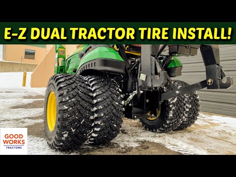
Unpin the nut and, while turning the wheel (to correctly place the rollers in the cages), tighten it until the force to rotate the wheel behind the tread is about 45 N (no more).
Cotter the nut, replace the cap, lower the wheel and remove the jack.
In the same sequence, check and, if necessary, adjust the bearings of the second front wheel of the tractor.
Adjustment of the wheel bearings of a tractor with a wheel arrangement 4K4 (using the MTZ-82 tractor as an example). With proper adjustment and operation of the tractor, an axial clearance of more than 0.3 mm appears in the bearings after 5 ... 6 thousand hours of operation, and it is eliminated during the repair of the tractor. Nevertheless, if, when checking before the specified period, a gap exceeding the norm is found, then eliminate it in this sequence.
Loosen the nuts and remove the disc together with the pneumatic tire. Drain the oil from the front wheel gearbox.
Detach the cover from the housing (Fig.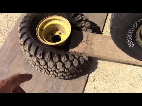 88, c) together with the driven gear and bearings.
Tighten the screws. If they lend themselves to tightening, this means that the cause of the increased clearance is insufficiently tightened screws. After that, put the removed part of the gearbox in place and check the axial clearance again. If the gap is within the normal range, fix the screws 6 with a folding plate, put the removed parts in place and fill the gearbox with oil.
If, after tightening the screws, the clearance in the bearings exceeds 0.2 mm, then again remove the cover with the driven gear and adjusting rings 7 and sand the end of one of them with sandpaper to the desired value. After assembly, check the gap, fix the screws 6 with a folding plate and fill the gearbox with oil.
Open Pivot Track Maintenance.
During the operation of a tracked tractor, part of the engine power is spent on friction in the joints of the track chains and in the engagement of the chains with the drive sprockets. This is affected by the degree of tension of the tracks. Excessively high tension increases friction as well as wear on parts. Insufficient tension increases the power loss due to the runout of the tracks, and in some cases leads to their jumping off.
Fig. 89. Checking the condition of the caterpillar tracks of tractors: a _ T-74, DT-75M and T-150; b - T-54S and T-70S.
The wear of crawler tractor propellers depends not only on the degree of track tension, but to a large extent on the type of soil on which the tractor is working. For example, wear of caterpillars on sandy soils is almost 2 times higher than wear on chernozems for the same period of time.
When track parts wear, the pitch increases, which weakens the track tension and in turn causes increased wear on the drive sprocket.
Worn track pins cause accelerated wear of the link eyes, and uneven wear of the right and left tracks disrupts the straightness of the tractor, which greatly tires the tractor operator.
To prolong the life of the track, it is necessary to carefully and timely monitor its wear, as well as its correct tension.
Tracks of tractors T-74, DT-75M and T-150 are checked on a horizontal hard platform. First, the caterpillar must be thoroughly cleaned of dirt and rinsed with water.
The first check after putting a new tractor into operation is scheduled after 600...700 hours of operation on sandy soils or after 1200...1400 hours of operation on chernozems. To do this, measure the length of 10 links (both tracks) located under the tractor (Fig. 89, a). The length of 10 links of both tracks should be the same and not higher than 1750 ... 1760 mm. If the size is within the specified limits, but differs by 10 mm for different tracks, then swap them.
The second check is 500 hours after the first when working on sandy soils or after 1000 hours on black soils. The length of 10 links should not exceed 1810 ... 1820 mm, but in this case it is necessary to replace the track pins with new ones and, in addition, swap the tractor drive sprockets.
If the links are worn through the pins, the tracks must be rotated 180° and swapped.
Checking the caterpillars of tractors T-54S and T-70S. The procedure for checking the degree of wear is the same as described above, with the only difference that for these tractors, the length of five links should be measured (Fig. 89.6).
For tracks with a width of 300 mm, when increasing the length of the five links to 920…930 mm, it is necessary to replace the pins with new ones. The second set of fingers must be placed when the length increases to 930 ... 940 mm and the third - up to 940 ... 950 mm.
For tracks with a width of 200 mm, when increasing the length L of five links from 880 to 920 mm, cut the locking brackets, knock out the pins and press out the bushings. Then turn the bushings 180° and press them back into place. The groove of the sleeve must be in its original position. Collect the caterpillar. When pressing out and pressing in the bushings and locking the pins, use special devices consisting of a pin, a conical guide bushing and a mandrel for locking the pins, which are attached to the tractor spare parts.
When the other side of the bushings is worn out, they must be replaced with new ones.
Put the caterpillar chains on the tractor so that the links on the lower branch are located with the side with two (for a chain 200 mm wide) or three (for a chain 300 mm wide) lugs in the direction of tractor movement forward. In this case, the finger heads must be outside the tractor.
Track check and tension. Clean, flush the tracks, and park the tractor on a level, firm surface with the track pins over the carrier rollers (before stopping, the tractor should only move forward to loosen the upper tracks).
Place the rail on the track chain lugs and use a ruler to measure the distance in the middle between the support rollers or the idler wheel and the support roller (Fig. 90, a).
Loosen the locknuts (Fig. 90.6), except for the T-150 tractor, and by turning the adjusting nut or shock absorber housing or pumping oil with a lever-plunger syringe, tighten the tracks.
When you have finished adjusting the tension, tighten the loose locknuts and lubricate the tension bolt threads with US grease.
If, during tensioning, the track of the T-150 tractor is very much extended and the crankshaft of the tension wheel comes into contact with the stop mounted on the frame, and is no longer able to tension the track to the desired size, then further injection of plastic lubricant is unacceptable, as this may cause damage to the tensioner. Unscrew the safety valve, move the wheel back (this will squeeze out the plastic lubricant through the hole from which the valve is turned out). Then separate the caterpillar, remove one link from it. Next, connect the caterpillar, put the valve in place and, while injecting plastic lubricant into the hydraulic cylinder, tension the caterpillar.
Fig. 90. Check (a) and tension (b) tracks
Fig. 91. Scheme of rearranging the carriages of a caterpillar tractor.
Rearrangement of suspension carriages. Every 1900...2000 hours of tractor operation rearrange the suspension carriages in a cross pattern (Fig. 91), which contributes to uniform wear of the carrier rollers.
Popular models John Deere 7830 and 7930 are included in the 7030 series of the third traction class. Tractors are characterized by a strong frame structure and a monoblock layout. But in order for them to serve properly for a long time, it is necessary to observe the timeliness of maintenance.
Photo source: act.su For long tractor operation it is important to observe the maintenance intervals
A number of actions must be performed for each working shift of the tractor:
In addition, the tractor tire inflation pressure should be checked weekly.
Photo source: act.su Prevention of "diseases" of the tractor begins with shift maintenance
Listed below are the recommended maintenance intervals for 500, 750, 1000, or 1500 hours.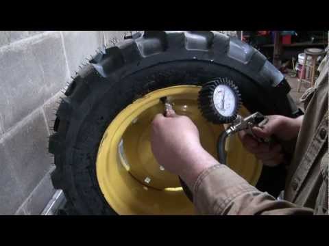
Agro-Construction Technologies specialists advise taking into account the following subtleties when servicing tractor equipment.
 The oil level in the sight glass will be significantly higher when the oil is hot and lower when it is cold.
 Photo source: act.suVarious types of tractor maintenance are carried out at intervals from 10 to 1500 hours
Photo source: act.suInspection of wheel tractor John Deere

 Use of this Web site constitutes acceptance of our User Agreement and Privacy Policy
 But since t ... [Read Article]
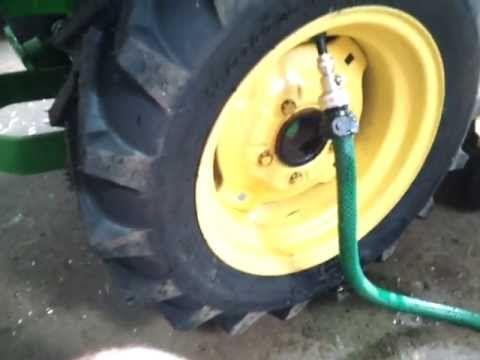 John Deere and its logos are the registered trademarks of the John Deere Corporation. Agco, Agco Allis, White, Massey Ferguson and their logos are the registered trademarks of AGCO Corporation. Case, Case-IH, Farmall, International Harvester, New Holland and their logos are registered trademarks of CNH Global N.V.